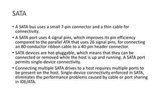
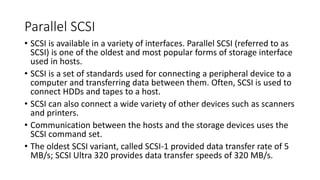
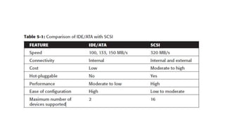
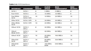
Information Storage and Management
Unit 3 – Direct Attached Storage and
Introduction to SCSI
Dr Mithun B N,
Asst. Prof. Dept of CSE, SOET,
CHRIST (Deemed to be University), Bengaluru-74.
Direct-Attached Storage
• Direct – Attached storage (DAS) is a an architecture where storage
connects directly to servers.
• Applications access data from DAS using block-level access protocols.
• DAS is ideal for localized data access and sharing in environments that
have a small number of servers.
• Ex: small businesses, departments and workgroups do not share
information across enterprises
Types of DAS
• There are two types of DAS depending on the location of the storage
device with respect to the host.
• Internal DAS
• External DAS
Internal DAS
• In the internal DAS architecture, the storage device is internally
connected to the host by a serial or parallel bus.
• The physical bus has distance limitations and can only be sustained
over a shorter distance for high-speed connectivity.
• Most internal buses can support only a limited number of devices
• They occupy a large amount of space inside the host, making
maintenance of other components difficult
External DAS
• In the external DAS
architecture, the server
connects directly to the external
storage device.
• Communication between the
host and the storage device
takes place over SCSI (Simple
Computer System Interconnect)
or FC (Fiber Channel) protocol.
DAS benefits and limitations
• DAS needs lower initial investment than storage networking.
• It is simple and can be deployed easily and rapidly.
• Setup is managed using host-based tools like host OS.
• It requires fewer management tasks and less hardware and software
elements to set up and operate.
• But it is not scalable.
DAS benefits and limitations
• A storage device has a limited number of ports.
• A limited bandwidth in DAS restricts the available I/O processing
capability.
• The distance limitations associated with implementing DAS because
of direct connectivity requirements can be addressed by using Fibre
Channel connectivity.
• Unused resources cannot be easily re-allocated, resulting in islands of
over-utilized and under-utilized storage pools.
DAS benefits and limitations
• Disk utilization, throughput, and cache memory of a storage device,
along with virtual memory of a host govern the performance of DAS.
• RAID-level configurations, storage controller protocols, and the
efficiency of the bus are additional factors that affect the
performance of DAS.
• The absence of storage interconnects and network latency provide
DAS with the potential to outperform other storage networking
configurations.
Disk Drive Interfaces
• The host and the storage device in DAS communicate with each other
by using predefined protocols such as IDE/ATA, SATA, SAS, SCSI, and
FC.
• These protocols are implemented on the HDD controller. Therefore, a
storage device is also known by the name of the protocol it supports.
IDE/ATA
• An Integrated Device Electronics/Advanced Technology Attachment
(IDE/ATA) disk supports the IDE protocol.
• The IDE component in IDE/ATA provides the specification for the
controllers connected to the computer’s motherboard for
communicating with the device attached.
• The ATA component is the interface for connecting storage devices, such
as CD-ROMs, floppy disk drives, and HDDs, to the motherboard.
• IDE/ATA has a variety of standards and names, such as ATA, ATA/ATAPI,
EIDE, ATA-2, Fast ATA, ATA-3, Ultra ATA, and Ultra DMA.
• The latest version of ATA—Ultra DMA/133—supports a throughput of
133 MB per second.
IDE/ATA
• In a master-slave configuration, an ATA
interface supports two storage devices per
connector. However, if the performance of
the drive is important, sharing a port
between two devices is not recommended.
• A 40-pin connector is used to connect ATA
disks to the motherboard, and a 34-pin
connector is used to connect floppy disk
drives to the motherboard.
• An IDE/ATA disk offers excellent
performance at low cost, making it a
popular and commonly used hard disk.
SATA
• A SATA (Serial ATA) is a serial version of the IDE/ATA specification.
• SATA is a disk-interface technology that was developed by a group of the
industry’s leading vendors with the aim of replacing parallel ATA.
• A SATA provides point-to-point connectivity up to a distance of one meter
and enables data transfer at a speed of 150 MB/s. Enhancements to the
SATA have increased the data transfer speed up to 600 MB/s.
• A SATA bus directly connects each storage device to the host through a
dedicated link, making use of low-voltage differential signaling (LVDS). LVDS
is an electrical signaling system that can provide high-speed connectivity
over low-cost, twisted-pair copper cables. For data transfer, a SATA bus uses
LVDS with a voltage of 250 mV.
SATA
• A SATA bus uses a small 7-pin connector and a thin cable for
connectivity.
• A SATA port uses 4 signal pins, which improves its pin efficiency
compared to the parallel ATA that uses 26 signal pins, for connecting
an 80-conductor ribbon cable to a 40-pin header connector.
• SATA devices are hot-pluggable, which means that they can be
connected or removed while the host is up and running. A SATA port
permits single-device connectivity.
• Connecting multiple SATA drives to a host requires multiple ports to
be present on the host. Single-device connectivity enforced in SATA,
eliminates the performance problems caused by cable or port sharing
in IDE/ATA.
Parallel SCSI
• SCSI is available in a variety of interfaces. Parallel SCSI (referred to as
SCSI) is one of the oldest and most popular forms of storage interface
used in hosts.
• SCSI is a set of standards used for connecting a peripheral device to a
computer and transferring data between them. Often, SCSI is used to
connect HDDs and tapes to a host.
• SCSI can also connect a wide variety of other devices such as scanners
and printers.
• Communication between the hosts and the storage devices uses the
SCSI command set.
• The oldest SCSI variant, called SCSI-1 provided data transfer rate of 5
MB/s; SCSI Ultra 320 provides data transfer speeds of 320 MB/s.
Introduction to Parallel SCSI
• Shugart Associates and NCR developed a system interface in 1981 and
named it Shugart Associates System Interface (SASI).
• The standard was updated to a more robust interface and renamed
SCSI. In 1986, the American National Standards Institution (ANSI)
acknowledged the new SCSI as an industry standard.
• SCSI, first developed for hard disks, is often compared to IDE/ATA.
• SCSI offers improved performance and expandability and
compatibility options, making it suitable for high-end computers.
However, the high cost associated with SCSI limits its popularity
among home or business desktop users.
Evolution of SCSI
• SCSI was developed to provide a device-independent mechanism for
attaching to and accessing host computers.
• SCSI also provided an efficient peer-to-peer I/O bus that supported
multiple devices.
• SCSI is commonly used as a hard disk interface. However, SCSI can be
used to add devices, such as tape drives and optical media drives, to
the host computer without modifying the system hardware or
software.
• Over the years, SCSI has undergone radical changes and has evolved
into a robust industry standard.
SCSI - 1
• SCSI-1, renamed to distinguish it from other SCSI versions, is the
original standard that the ANSI approved.
• SCSI-1 defined the basics of the first SCSI bus, including cable length,
signaling characteristics, commands, and transfer modes.
• SCSI-1 devices supported only single-ended transmission and passive
termination. SCSI-1 used a narrow 8-bit bus, which offered a
maximum data transfer rate of 5 MB/s.
• SCSI-1 implementations resulted in incompatible devices and several
subsets of standards.
SCSI – 2
• To control the various problems caused by the nonstandard
implementation of the original SCSI, a working paper was created to
define a set of standard commands for a SCSI device.
• The set of standards, called the common command set (CCS), formed
the basis of the SCSI-2 standard.
• SCSI-2 was focused on improving performance, enhancing reliability,
and adding additional features to the SCSI-1 interface, in addition to
standardizing and formalizing the SCSI commands.
• The transition from SCSI-1 to SCSI-2 did not raise much concern
because SCSI-2 offered backward compatibility with SCSI-1.
SCSI – 3
• In 1993, work began on developing the next version of the SCSI
standard, SCSI-3.
• Unlike SCSI-2, the SCSI-3 standard document is comprised different
but related standards, rather than one large document.
SCSI – 3 Architecture
• The SCSI-3 architecture defines and categorizes various SCSI-3
standards and requirements for SCSI-3 implementations.
• This architecture helps developers, hardware designers, and users to
understand and effectively utilize SCSI.
• The three major components of a SCSI architectural model are as
follows:
• SCSI-3 command protocol: This consists of primary commands that are
common to all devices as well as device-specific commands that are unique to
a given class of devices.
• Transport layer protocols: These are a standard set of rules by which devices
communicate and share information.
• Physical layer interconnects: These are interface details such as electrical
signaling methods and data transfer modes.
SCSI-3 client server model
• SCSI-3 architecture derives its base from the client-server relationship, in which a
client directs a service request to a server, which then fulfills the client’s request.
• In a SCSI-3 client-server model, a particular SCSI device acts as a SCSI target
device, a SCSI initiator device, or a SCSI target/initiator device.
• Each device performs the following functions:
• SCSI initiator device: Issues a command to the SCSI target device, to perform a
task. A SCSI host adaptor is an example of an initiator.
• SCSI target device: Executes commands to perform the task received from a SCSI
initiator. Typically a SCSI peripheral device acts as a target device. However, in
certain implementations, the host adaptor can also be a target device.
SCSI-3 client server model
• Figure displays the SCSI-3 client-server model, in which
a SCSI initiator, or a client, sends a request to a SCSI
target, or a server.
• The target performs the tasks requested and sends the
output to the initiator, using the protocol service
interface.
• A SCSI target device contains one or more logical units.
A logical unit is an object that implements one of the
device functional models as described in the SCSI
command standards.
• The logical unit processes the commands sent by a SCSI
initiator. A logical unit has two components, a device
server and a task manager, as shown in Figure.
• The device server addresses client requests, and the task
manager performs management functions.
SCSI-3 client server model
• The SCSI initiator device is comprised of an application client and task
management function, which initiates device service and task
management requests.
• Each device service request contains a Command Descriptor Block
(CDB).
• The CDB defines the command to be executed and lists command-
specific input sand other parameters specifying how to process the
command.
SCSI-3 client server model
• The SCSI devices are identified by a specific number called a SCSI ID.
In narrow SCSI (bus width=8), the devices are numbered 0 through 7;
in wide (bus width=16) SCSI, the devices are numbered 0 through 15.
These ID numbers set the device priorities on the SCSI bus.
• In narrow SCSI, 7 has the highest priority and 0 has the lowest
priority. In wide SCSI, the device IDs from 8 to 15 have the highest
priority, but the entire sequence of wide SCSI IDs has lower priority
than narrow SCSI IDs.
• Therefore, the overall priority sequence for a wide SCSI is 7, 6, 5, 4, 3,
2, 1, 0, 15, 14, 13, 12, 11, 10, 9, and 8.
SCSI - Ports
• SCSI ports are the physical
connectors that the SCSI cable
plugs into for communication with
a SCSI device.
• A SCSI device may contain target
ports, initiator ports,
target/initiator ports, or a target
with multiple ports. Based on the
port combinations, a SCSI device
can be classified as an initiator
model, a target model, a combined
model, or a target model with
multiple ports.

Direct Attached Storage - Information Storage and Management.pptx

  • 1.
    Information Storage andManagement Unit 3 – Direct Attached Storage and Introduction to SCSI Dr Mithun B N, Asst. Prof. Dept of CSE, SOET, CHRIST (Deemed to be University), Bengaluru-74.
  • 2.
    Direct-Attached Storage • Direct– Attached storage (DAS) is a an architecture where storage connects directly to servers. • Applications access data from DAS using block-level access protocols. • DAS is ideal for localized data access and sharing in environments that have a small number of servers. • Ex: small businesses, departments and workgroups do not share information across enterprises
  • 3.
    Types of DAS •There are two types of DAS depending on the location of the storage device with respect to the host. • Internal DAS • External DAS
  • 4.
    Internal DAS • Inthe internal DAS architecture, the storage device is internally connected to the host by a serial or parallel bus. • The physical bus has distance limitations and can only be sustained over a shorter distance for high-speed connectivity. • Most internal buses can support only a limited number of devices • They occupy a large amount of space inside the host, making maintenance of other components difficult
  • 5.
    External DAS • Inthe external DAS architecture, the server connects directly to the external storage device. • Communication between the host and the storage device takes place over SCSI (Simple Computer System Interconnect) or FC (Fiber Channel) protocol.
  • 6.
    DAS benefits andlimitations • DAS needs lower initial investment than storage networking. • It is simple and can be deployed easily and rapidly. • Setup is managed using host-based tools like host OS. • It requires fewer management tasks and less hardware and software elements to set up and operate. • But it is not scalable.
  • 7.
    DAS benefits andlimitations • A storage device has a limited number of ports. • A limited bandwidth in DAS restricts the available I/O processing capability. • The distance limitations associated with implementing DAS because of direct connectivity requirements can be addressed by using Fibre Channel connectivity. • Unused resources cannot be easily re-allocated, resulting in islands of over-utilized and under-utilized storage pools.
  • 8.
    DAS benefits andlimitations • Disk utilization, throughput, and cache memory of a storage device, along with virtual memory of a host govern the performance of DAS. • RAID-level configurations, storage controller protocols, and the efficiency of the bus are additional factors that affect the performance of DAS. • The absence of storage interconnects and network latency provide DAS with the potential to outperform other storage networking configurations.
  • 9.
    Disk Drive Interfaces •The host and the storage device in DAS communicate with each other by using predefined protocols such as IDE/ATA, SATA, SAS, SCSI, and FC. • These protocols are implemented on the HDD controller. Therefore, a storage device is also known by the name of the protocol it supports.
  • 10.
    IDE/ATA • An IntegratedDevice Electronics/Advanced Technology Attachment (IDE/ATA) disk supports the IDE protocol. • The IDE component in IDE/ATA provides the specification for the controllers connected to the computer’s motherboard for communicating with the device attached. • The ATA component is the interface for connecting storage devices, such as CD-ROMs, floppy disk drives, and HDDs, to the motherboard. • IDE/ATA has a variety of standards and names, such as ATA, ATA/ATAPI, EIDE, ATA-2, Fast ATA, ATA-3, Ultra ATA, and Ultra DMA. • The latest version of ATA—Ultra DMA/133—supports a throughput of 133 MB per second.
  • 11.
    IDE/ATA • In amaster-slave configuration, an ATA interface supports two storage devices per connector. However, if the performance of the drive is important, sharing a port between two devices is not recommended. • A 40-pin connector is used to connect ATA disks to the motherboard, and a 34-pin connector is used to connect floppy disk drives to the motherboard. • An IDE/ATA disk offers excellent performance at low cost, making it a popular and commonly used hard disk.
  • 12.
    SATA • A SATA(Serial ATA) is a serial version of the IDE/ATA specification. • SATA is a disk-interface technology that was developed by a group of the industry’s leading vendors with the aim of replacing parallel ATA. • A SATA provides point-to-point connectivity up to a distance of one meter and enables data transfer at a speed of 150 MB/s. Enhancements to the SATA have increased the data transfer speed up to 600 MB/s. • A SATA bus directly connects each storage device to the host through a dedicated link, making use of low-voltage differential signaling (LVDS). LVDS is an electrical signaling system that can provide high-speed connectivity over low-cost, twisted-pair copper cables. For data transfer, a SATA bus uses LVDS with a voltage of 250 mV.
  • 13.
    SATA • A SATAbus uses a small 7-pin connector and a thin cable for connectivity. • A SATA port uses 4 signal pins, which improves its pin efficiency compared to the parallel ATA that uses 26 signal pins, for connecting an 80-conductor ribbon cable to a 40-pin header connector. • SATA devices are hot-pluggable, which means that they can be connected or removed while the host is up and running. A SATA port permits single-device connectivity. • Connecting multiple SATA drives to a host requires multiple ports to be present on the host. Single-device connectivity enforced in SATA, eliminates the performance problems caused by cable or port sharing in IDE/ATA.
  • 14.
    Parallel SCSI • SCSIis available in a variety of interfaces. Parallel SCSI (referred to as SCSI) is one of the oldest and most popular forms of storage interface used in hosts. • SCSI is a set of standards used for connecting a peripheral device to a computer and transferring data between them. Often, SCSI is used to connect HDDs and tapes to a host. • SCSI can also connect a wide variety of other devices such as scanners and printers. • Communication between the hosts and the storage devices uses the SCSI command set. • The oldest SCSI variant, called SCSI-1 provided data transfer rate of 5 MB/s; SCSI Ultra 320 provides data transfer speeds of 320 MB/s.
  • 16.
    Introduction to ParallelSCSI • Shugart Associates and NCR developed a system interface in 1981 and named it Shugart Associates System Interface (SASI). • The standard was updated to a more robust interface and renamed SCSI. In 1986, the American National Standards Institution (ANSI) acknowledged the new SCSI as an industry standard. • SCSI, first developed for hard disks, is often compared to IDE/ATA. • SCSI offers improved performance and expandability and compatibility options, making it suitable for high-end computers. However, the high cost associated with SCSI limits its popularity among home or business desktop users.
  • 17.
    Evolution of SCSI •SCSI was developed to provide a device-independent mechanism for attaching to and accessing host computers. • SCSI also provided an efficient peer-to-peer I/O bus that supported multiple devices. • SCSI is commonly used as a hard disk interface. However, SCSI can be used to add devices, such as tape drives and optical media drives, to the host computer without modifying the system hardware or software. • Over the years, SCSI has undergone radical changes and has evolved into a robust industry standard.
  • 18.
    SCSI - 1 •SCSI-1, renamed to distinguish it from other SCSI versions, is the original standard that the ANSI approved. • SCSI-1 defined the basics of the first SCSI bus, including cable length, signaling characteristics, commands, and transfer modes. • SCSI-1 devices supported only single-ended transmission and passive termination. SCSI-1 used a narrow 8-bit bus, which offered a maximum data transfer rate of 5 MB/s. • SCSI-1 implementations resulted in incompatible devices and several subsets of standards.
  • 19.
    SCSI – 2 •To control the various problems caused by the nonstandard implementation of the original SCSI, a working paper was created to define a set of standard commands for a SCSI device. • The set of standards, called the common command set (CCS), formed the basis of the SCSI-2 standard. • SCSI-2 was focused on improving performance, enhancing reliability, and adding additional features to the SCSI-1 interface, in addition to standardizing and formalizing the SCSI commands. • The transition from SCSI-1 to SCSI-2 did not raise much concern because SCSI-2 offered backward compatibility with SCSI-1.
  • 20.
    SCSI – 3 •In 1993, work began on developing the next version of the SCSI standard, SCSI-3. • Unlike SCSI-2, the SCSI-3 standard document is comprised different but related standards, rather than one large document.
  • 22.
    SCSI – 3Architecture • The SCSI-3 architecture defines and categorizes various SCSI-3 standards and requirements for SCSI-3 implementations. • This architecture helps developers, hardware designers, and users to understand and effectively utilize SCSI. • The three major components of a SCSI architectural model are as follows: • SCSI-3 command protocol: This consists of primary commands that are common to all devices as well as device-specific commands that are unique to a given class of devices. • Transport layer protocols: These are a standard set of rules by which devices communicate and share information. • Physical layer interconnects: These are interface details such as electrical signaling methods and data transfer modes.
  • 24.
    SCSI-3 client servermodel • SCSI-3 architecture derives its base from the client-server relationship, in which a client directs a service request to a server, which then fulfills the client’s request. • In a SCSI-3 client-server model, a particular SCSI device acts as a SCSI target device, a SCSI initiator device, or a SCSI target/initiator device. • Each device performs the following functions: • SCSI initiator device: Issues a command to the SCSI target device, to perform a task. A SCSI host adaptor is an example of an initiator. • SCSI target device: Executes commands to perform the task received from a SCSI initiator. Typically a SCSI peripheral device acts as a target device. However, in certain implementations, the host adaptor can also be a target device.
  • 25.
    SCSI-3 client servermodel • Figure displays the SCSI-3 client-server model, in which a SCSI initiator, or a client, sends a request to a SCSI target, or a server. • The target performs the tasks requested and sends the output to the initiator, using the protocol service interface. • A SCSI target device contains one or more logical units. A logical unit is an object that implements one of the device functional models as described in the SCSI command standards. • The logical unit processes the commands sent by a SCSI initiator. A logical unit has two components, a device server and a task manager, as shown in Figure. • The device server addresses client requests, and the task manager performs management functions.
  • 26.
    SCSI-3 client servermodel • The SCSI initiator device is comprised of an application client and task management function, which initiates device service and task management requests. • Each device service request contains a Command Descriptor Block (CDB). • The CDB defines the command to be executed and lists command- specific input sand other parameters specifying how to process the command.
  • 27.
    SCSI-3 client servermodel • The SCSI devices are identified by a specific number called a SCSI ID. In narrow SCSI (bus width=8), the devices are numbered 0 through 7; in wide (bus width=16) SCSI, the devices are numbered 0 through 15. These ID numbers set the device priorities on the SCSI bus. • In narrow SCSI, 7 has the highest priority and 0 has the lowest priority. In wide SCSI, the device IDs from 8 to 15 have the highest priority, but the entire sequence of wide SCSI IDs has lower priority than narrow SCSI IDs. • Therefore, the overall priority sequence for a wide SCSI is 7, 6, 5, 4, 3, 2, 1, 0, 15, 14, 13, 12, 11, 10, 9, and 8.
  • 28.
    SCSI - Ports •SCSI ports are the physical connectors that the SCSI cable plugs into for communication with a SCSI device. • A SCSI device may contain target ports, initiator ports, target/initiator ports, or a target with multiple ports. Based on the port combinations, a SCSI device can be classified as an initiator model, a target model, a combined model, or a target model with multiple ports.