Downloaded 141 times


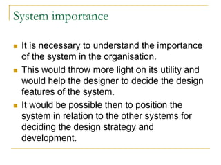


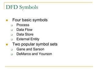


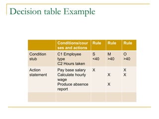


The document discusses system analysis and development models. It describes the need for system analysis from various points of view like system objectives, boundaries, importance, etc. It then explains the key stages in system analysis like system study, feasibility study, system analysis, system design, coding, testing, implementation and maintenance. It also discusses various system analysis tools like data flow diagrams, decision tables, etc.