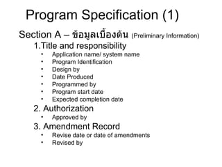
Section A – ข้อมูลเบื้องต้น ( Preliminary Information) 1.Title and responsibility Application name/ system name Program Identification Design by Date Produced Programmed by Program start date Expected completion date 2. Authorization Approved by 3. Amendment Record Revise date or date of amendments Revised by Program Specification (1)
5.
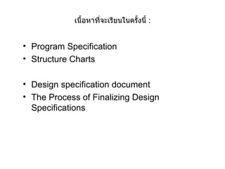
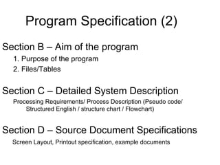
Section B –Aim of the program 1. Purpose of the program 2. Files/Tables Section C – Detailed System Description Processing Requirements/ Process Description (Pseudo code/ Structured English / structure chart / Flowchart) Section D – Source Document Specifications Screen Layout, Printout specification, example documents Program Specification (2)
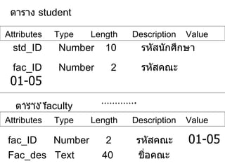
ตาราง studentAttributes Type Length Description Value std_ID Number 10 รหัสนักศึกษา fac_ID Number 2 รหัสคณะ 01 -05 …… .. …………. ตาราง faculty Attributes Type Length Description Value fac_ID Number 2 รหัสคณะ 01 -05 Fac_des Text 40 ชื่อคณะ
10.
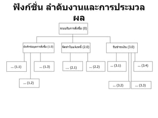
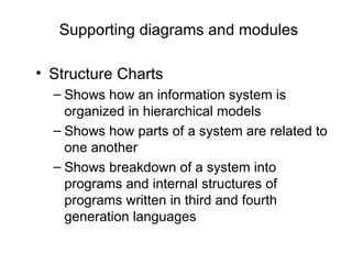
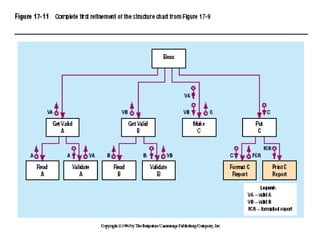
Supporting diagrams andmodules Structure Charts Shows how an information system is organized in hierarchical models Shows how parts of a system are related to one another Shows breakdown of a system into programs and internal structures of programs written in third and fourth generation languages
11.
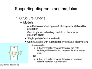
Supporting diagrams andmodules Structure Charts Module A self-contained component of a system, defined by a function One single coordinating module at the root of structure chart Single point of entry and exit Communicate with each other by passing parameters Data couple A diagrammatic representation of the data exchanged between two modules in a structure chart Flag A diagrammatic representation of a message passed between two modules
12.
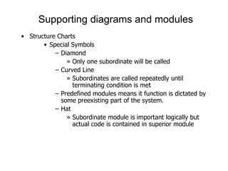
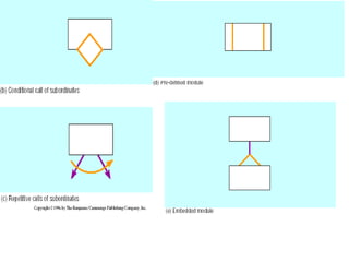
Supporting diagrams andmodules Structure Charts Special Symbols Diamond Only one subordinate will be called Curved Line Subordinates are called repeatedly until terminating condition is met Predefined modules means it function is dictated by some preexisting part of the system. Hat Subordinate module is important logically but actual code is contained in superior module
13.
14.
15.
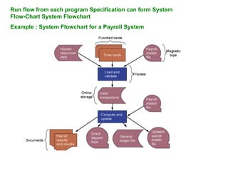
Run flow fromeach program Specification can form System Flow-Chart System Flowchart Example : System Flowchart for a Payroll System
16.
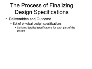
The Process ofFinalizing Design Specifications Deliverables and Outcome Set of physical design specifications Contains detailed specifications for each part of the system
17.
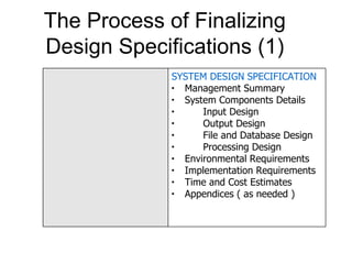
The Process ofFinalizing Design Specifications (1) SYSTEM DESIGN SPECIFICATION Management Summary System Components Details Input Design Output Design File and Database Design Processing Design Environmental Requirements Implementation Requirements Time and Cost Estimates Appendices ( as needed )
18.
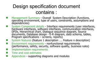
Management Summary - Overall System Description (functions, operating environment, type of users, constraints, assumptions and dependencies) System Component details - Interface requirements (user interfaces, hardware interfaces, software interfaces, communication interfaces, DFDs, Hierarchical chart, Dialogue sequence diagram, Source documents, Database design - E-R diagram, data schema, tables, Program specifications – screens, reports) System features (feature 1 description …. Feature n description) Environment requirements - nonfunctional requirements (performance, safety, security, software quality, business rules) Implementation requirements Time and cost estimates Appendices - supporting diagrams and modules Design specification document contains :
19.
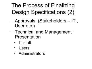
The Process ofFinalizing Design Specifications (2) Approvals (Stakeholders – IT , User etc.) Technical and Management Presentation IT staff Users Administrators