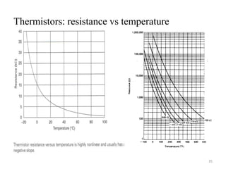
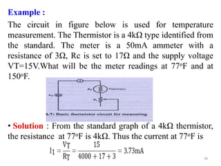
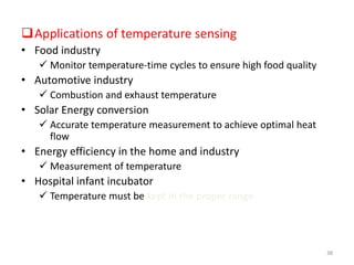
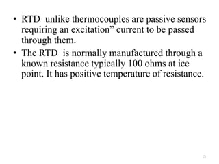
Thermocouples, resistance temperature detectors (RTDs), and thermistors are the three main types of temperature transducers. Thermocouples generate a voltage proportional to temperature difference by joining two dissimilar metals. RTDs measure temperature by relating the precise resistance change of materials like platinum to temperature. Thermistors are semiconductors whose high resistance changes significantly with temperature. Each transducer has advantages - thermocouples cover a wide range but with low accuracy, while RTDs and thermistors offer higher accuracy over smaller ranges. Applications include temperature monitoring and control in industries like food processing, automotive, solar energy, and healthcare.

![ RTD -Linear or Straight line equation
approximation
R(T)= approximation of resistance at temperature T
R(T0)= resistance at temperature T0
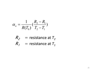
αo = fractional change in resistance per degree of temperature
at T0
ΔT= T - T0
2
1
]
1
)[
(
)
( T
T
T
T
T
R
T
R o
o
19](https://image.slidesharecdn.com/temperaturetransducers-231213134738-bbf82305/85/Temperature-Transducers-pptx-19-320.jpg)
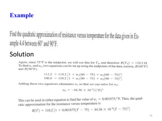
![RTD – quadratic approximation
• More accurate representation of R-T curve over some span
of temperatures.
R(T) = quadratic approximation of resistance at temperature T
R(T0)= resistance at temperature T0
α1 = linear fractional change in resistance with temperature
α2 = quadratic fractional change in resistance with temperature
ΔT = T - T0
2
1
2
2
1 ]
)
(
1
)[
(
)
( T
T
T
T
T
T
R
T
R o
22](https://image.slidesharecdn.com/temperaturetransducers-231213134738-bbf82305/85/Temperature-Transducers-pptx-22-320.jpg)