Download to read offline
![International Research Journal of Engineering and Technology (IRJET) e-ISSN: 2395 -0056
Volume: 04 Issue: 02 | Feb -2017 www.irjet.net p-ISSN: 2395-0072
© 2017, IRJET | Impact Factor value: 5.181 | ISO 9001:2008 Certified Journal | Page 1323
Review on Automation Tool for ERD Normalization
A.S.Gaikwad, F.A.Kadri, S.S.Khandagle,N.I.Tava
Student, Department of Computer Engineering, MET'S BKC IOE Nashik, Maharashtra, India
Guided by Prof.Madhuri Shinde.
Department of Computer Engineering, MET BKC
---------------------------------------------------------------------***---------------------------------------------------------------------
Abstract - Entity Relationship Diagram (ERD) is the first
step in database design; it is an important step for the
database designers, users, analyst, and managers and in
software engineering. In this paper, a methodology for
detection of ambiguity in the ERD diagram is given. If
ambiguity is found then apply various normalization
techniques to remove it. The Normalization algorithms that
are included are – 1NF, 2NF. This methodology is based on a
predefined set of a heuristic rules that aims to extract the
ambiguity of the ERD, then these rules are mapped into a
database. A diagram generator automatically converts ERD
into database schema's or table according to the rules of
generations. The proposed methodology is explained by the
examples to show how it can provide a mechanism for quick
and easy way in extracting the Database Schemas.
Key Words: Entity RelationshipDiagram, entity, relationship,
attribute
1. INTRODUCTION
The Entity Relationship Diagram (ERD) shows that the real
world consists of a collection of entities, the relationships
between them, and the attributes that describe them. An
entity is the object where we want to store data. A
relationship defines the allowed connections between
instances of entities [1]. Attributeisa characteristic common
to all or most instances of a particular entity. Since the ER
approach is easy to understand, a designer can focus on
conceptual modeling of an organization, making decisions
of what to use from entity sets, relationship sets and
constraints. The ER-Diagram tool provides a mechanism for
quickly and easily modeling data structures required by a
software system. The ERD tool provides all the usual
features of a data modeling tool and additionally provides
reverse engineering. Thus, the user can create a database
system quickly on a number of different target platforms
without the need to write any Data Definition Language
(DDL) type code. There are many essential concepts
between ERD structure and English grammar structure
[3] after analyzing the English sentences, so it is easy to
make mapping between them.
This paper describes a methodology, which is able to extract
the ERD from a description of the application domain given
in English sentences. Using ER-extractor it extracts entities
relationships and attributes according to the heuristic rules
it will be defined, as well as by matching between the
structures of both English and ERD structures. After that,
ER-generator depends on the predicate to convert the
structure, which next pass the ER-descriptor to start to
draw the ERD automatically depending on the rules. This
paper proposed to define a methodology that provide a
help to the database designer to automatically extract the
ERD from a given English sentences. ERD is the first step
in database design, it is also a simple technique described in
a graphical way to decide which database fields,
relationships and tables will be the base of any database.
ERD is a good communication tool between users and who
use the system during the identification of the user
information requirements process.
2. EXISTING SYSTEM
There is face-to-face interaction in traditional environment.
The data normalization is introduced in this environment.
DBMS is directly saved in the database whereas files locally
act. Transactions are not possible in file systems; whereas
various types of transactions are possible in DBMS like
insert, view, delete, update etc. In DBMS, for accessing data
tables i.e. schema is used whereas in file systems data is
access is done through various files. In file systems to store
different relationships in directories “File Manager” is used;
whereas to store the relationships in the form of structural
tables, a database manager i.e. administrator is used.
Therefore, the data in database is moresecureascompare to
data in file systems.
Various tools are available that allows database designers to
draw and model the ER diagram. The given section provides
an overview of the tool sets that are considered to define ER
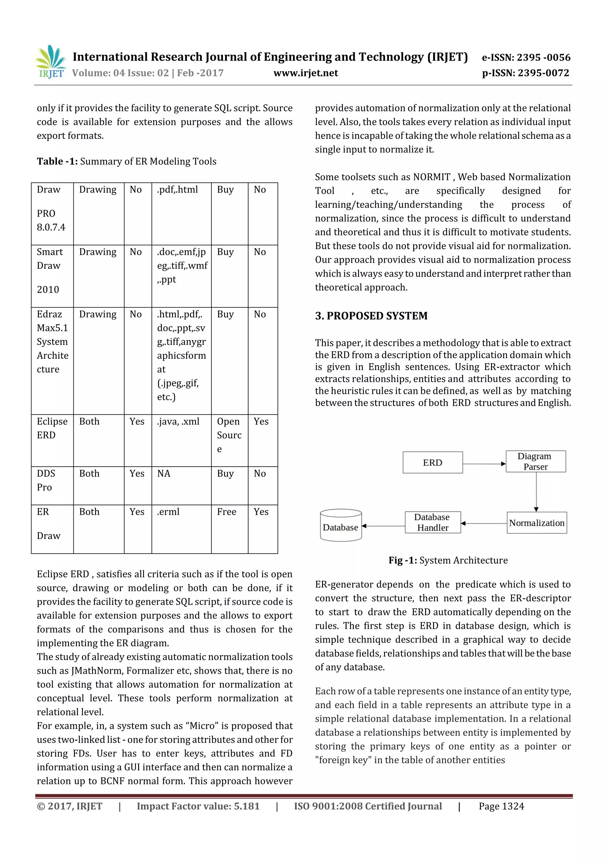
Diagrams for extending the ER Model. Summary and
comparisons of all the modeling tools and ER drawings used
in Chen like model is provided for ER definitions in Table 1.
Comparison of tools is based on the criteria such that if the
tool is open source or need to buy, draw or model or both,](https://image.slidesharecdn.com/irjet-v4i2259-171120063723/75/Review-on-Automation-Tool-for-ERD-Normalization-1-2048.jpg)
![International Research Journal of Engineering and Technology (IRJET) e-ISSN: 2395 -0056
Volume: 04 Issue: 02 | Feb -2017 www.irjet.net p-ISSN: 2395-0072
© 2017, IRJET | Impact Factor value: 5.181 | ISO 9001:2008 Certified Journal | Page 1325
There is a tradition for ER/data models to be built at two to
three levels of abstraction.
Some advantages of proposed system is as follows.
1. Reduction in data redundancy.
2. Increased consistency andreducedupdatingerrors.
3. Independence from applications programs and
greater data integrity.
4. Improvised data access to users through useofhost
and query languages.
5. Improved security of data.
6. Reduced storage, data entry, and retrieval costs.
7. Facilitated development in new applications
programs.
4. CONCLUSIONS
Since the real world consists of a collection of entities
and relationship between them with attributes that
describes them, extracting database from ERD is an
important step to understand the entire system. ERD
supplement data modeling, and also considered to be the
base approach for database designers and software
developers. In future, we can extend ER diagram
normalization using the parallel processing framework so
that it can handle very big diagram in efficient manner.
REFERENCES
[1]. Adelman, S., Moss, Larissa and Abai, Majid (2005) Data
Strategy, Addison-Wesley, Readings, MA.
[2]. Bala, Mohan and Martin, Kipp (1997) “A Mathematical
Programming Approach to Data Base Normalization,”
Informs Journal of Computing, Vol. 9, No.1, pp. 1-14.
[3].Balaban, M. and Shoval, P. (1999). Enhancing the ER
model with integrity methods. Journal of Database
Management, 10(4),14-23.
BIOGRAPHIES
Nazneen I .Tava currently perusing BE
in Computer Engineering from MET’S
Bhujbal Knowledge city, Institute of
Engineering , Adgaon , Nasik
,Maharashtra, India from 2014.My area
of interest is Database Normalization
and Networking.](https://image.slidesharecdn.com/irjet-v4i2259-171120063723/75/Review-on-Automation-Tool-for-ERD-Normalization-3-2048.jpg)

The document describes a methodology for automatically extracting entity relationship diagrams (ERDs) from English language descriptions. It involves using heuristic rules to extract entities, relationships, and attributes from text and then generating an ERD. The proposed system aims to provide a quick and easy way for database designers to generate ERDs from requirements documents. Existing normalization tools only operate on relational schemas and do not support conceptual-level normalization of ERDs. The proposed system would extract ERDs and then apply normalization techniques like 1NF and 2NF to remove ambiguities and inconsistencies from the initial ERD.


![[Www.pkbulk.blogspot.com]dbms01](https://cdn.slidesharecdn.com/ss_thumbnails/www-pkbul-blogspot-comdbms01-130615034553-phpapp01-thumbnail.jpg?width=640&height=640&fit=bounds)