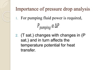
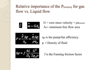
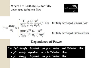
1. Heat exchanger pressure drop analysis is important because pumping power required is directly related to pressure drop and pressure drop affects heat transfer, operation, size, and cost.
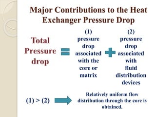
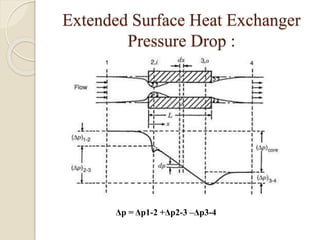
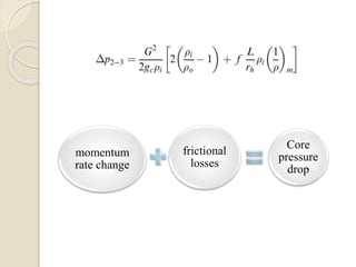
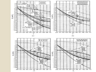
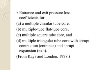
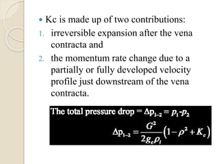
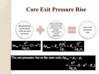
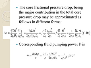
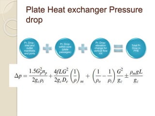
2. Major contributions to pressure drop include friction in the core and distribution devices, with core pressure drop dominated by friction, momentum effects, and entrance/exit effects.
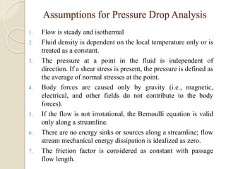
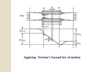
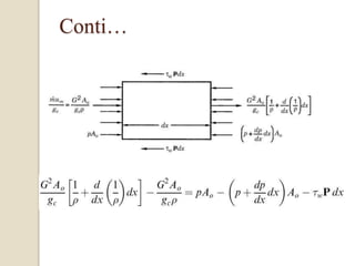
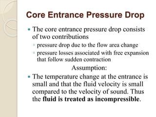
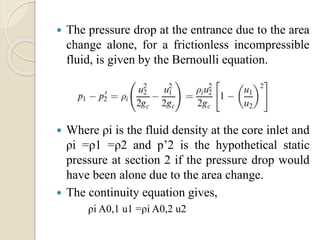
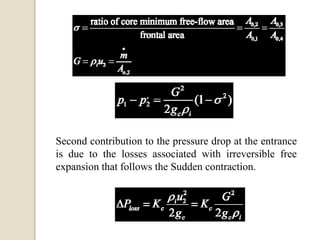
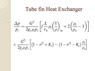
3. Core pressure drop is analyzed using assumptions of steady, isothermal flow and accounting for friction, momentum effects, and entrance/exit contractions based on flow geometry and properties.