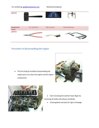
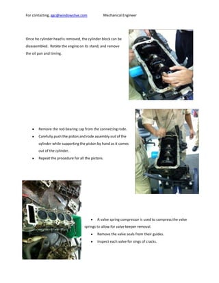
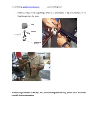
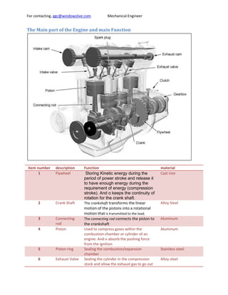
This document provides information about disassembling and reassembling an internal combustion engine. It describes the key parts of the engine and their functions. The main steps taken to disassemble the engine are cleaning it, removing the cylinder head and other components. Assembly is done in reverse order. The four strokes of the engine cycle are also explained: intake, compression, ignition, and exhaust. Differences between this engine and others are noted, such as arrangement and valve design.
Complete guide to Internal Combustion engines (IC engines)Syed Yaseen
The following presentation is a part of an online course called "A brief overview of IC engine". The presentation contains complete information about IC engines and will be helpful for students of Mechanical and Automobile engineering. The presentation is full of graphics to reduce the efforts of students for imagination and help them to understand the concept as soon as possible.
Do you know what is engine, how many types of engines are available now. How conversion of energy takes place from chemical energy to mechanical energy or useful work. Here engine classified according to their combustion, working stroke, arrangement of piston, fuel used for combustion and on the basis of ignition system. 4-stroke petrol engine and 4-stroke diesel engine are described briefly with all 4-strokes which are completed during power conversion process. 2-stroke engine or scooter engine is also described briefly with the complete details of combustion, charge( petrol,diesel ) filling process and how all 4 stroke process(suction, combustion,power stroke, exhaust) completed in 2 stroke engine.
this presentation explains the engine components and 4 stroke cycle engine operations. it also includes other activities that might help the students in understanding the 4 stroke cycle engine operation.
presentation of safety role of management. you will find the information that you need to present it in the report. you can download the report in my uploads.
Economy report of UAE . this report is only for United Arab Emirates. This project shows you how to make proper economy report for any country. Students who study Economy at university, they really need to read this report. I call it project because it's huge of information and it's complete.
In structural design, torsional moment may, on occasion, be a significant force for which
provision must be made. The most efficient shape for carrying a torque is a hollow circular shaft;
extensive treatment of torsion and torsion combined with bending and axial force is to be found
in most texts on mechanics of materials.
When a simple circular solid shaft is twisted, the shearing stress at any point on a transverse
cross-section varies directly as the distance from the center of the shaft. Thus, during twisting,
the cross-section which is initially planar remains a plane and rotates only about the axis of the
shaft.
Torsion members are frequently encountered in structures and machines. A structural member
may need to resist torques induced by a load, such as wind or gravity. Machinery examples
include motor vehicle drive shafts, torsion bar suspensions, ship propeller shafts, and centrifugal
pump shafts. In the analysis of torsionally loaded members, we are primarily concerned with the
torsion stress and the angle of twist on the shaft. In our laboratory experiment, the primary
emphasis is on the recognition of torsion on the usual structural members, how the torsion
stresses may be approximated and how such members may be selected to resist torsion effects.
This project is to cover the graduation requirements for high Diploma of Higher College Of Technology. The research was on the earthquakes and it effects on the building. After that , designing system that help us to control the effect of earthquakes. This system has structure components that should be under consideration. Also, installing the Tuned Mass Dumper TMD in the structure and superstructure of building. This consisting of mass, spring and viscous dumper. The viscous dumper will absorb the energy of the vibration due to earthquakes. Part of calculations, it’s important to study the Flexibility influence coefficient. It focuses on the behavior in terms of stiffness and flexibility. Another important subject is mass stiffness and matrices. This provides the simplest representation of a building for the purposes of investigating lateral dynamic responses.
You could be a professional graphic designer and still make mistakes. There is always the possibility of human error. On the other hand if you’re not a designer, the chances of making some common graphic design mistakes are even higher. Because you don’t know what you don’t know. That’s where this blog comes in. To make your job easier and help you create better designs, we have put together a list of common graphic design mistakes that you need to avoid.
Expert Accessory Dwelling Unit (ADU) Drafting ServicesResDraft
Whether you’re looking to create a guest house, a rental unit, or a private retreat, our experienced team will design a space that complements your existing home and maximizes your investment. We provide personalized, comprehensive expert accessory dwelling unit (ADU)drafting solutions tailored to your needs, ensuring a seamless process from concept to completion.
Hello everyone! I am thrilled to present my latest portfolio on LinkedIn, marking the culmination of my architectural journey thus far. Over the span of five years, I've been fortunate to acquire a wealth of knowledge under the guidance of esteemed professors and industry mentors. From rigorous academic pursuits to practical engagements, each experience has contributed to my growth and refinement as an architecture student. This portfolio not only showcases my projects but also underscores my attention to detail and to innovative architecture as a profession.
White wonder, Work developed by Eva TschoppMansi Shah
White Wonder by Eva Tschopp
A tale about our culture around the use of fertilizers and pesticides visiting small farms around Ahmedabad in Matar and Shilaj.
Between Filth and Fortune- Urban Cattle Foraging Realities by Devi S Nair, An...Mansi Shah
This study examines cattle rearing in urban and rural settings, focusing on milk production and consumption. By exploring a case in Ahmedabad, it highlights the challenges and processes in dairy farming across different environments, emphasising the need for sustainable practices and the essential role of milk in daily consumption.
1. For contacting, ggc@windowslive.com Mechanical Engineer
Table of Contents
IC Engine Practical ......................................................................................................................................... 2
Introduction and objective ....................................................................................................................... 2
Equipment and tools used ........................................................................................................................ 2
Procedure................................................................................................... Error! Bookmark not defined.
The Main part of the Engine and main Function ...................................................................................... 6
The operation principle of 4 stroke engine............................................................................................... 8
Intake stroke ......................................................................................................................................... 8
Compression stroke .............................................................................................................................. 8
Ignition stroke ....................................................................................................................................... 8
PV diagram ................................................................................................................................................ 9
Differences between our engine and others engines............................................................................. 10
Extra information .................................................................................................................................... 10
Arrangement for IC four stroke .......................................................................................................... 10
2. For contacting, ggc@windowslive.com Mechanical Engineer
IC Engine Practical
Introduction and objective
What meant by IC engine is internal combustion Engine as one type of the engines. In
this particular engine, the burning of fuel inside the cylinder (chemical reaction resulting thermal
energy) will increase in pressure which needs more volume to be occupied by the gas. That will
derive the piston to move downward to bottom dead center of the cylinder. That will result
mechanical motion (linearly) which will transfer to rotary motion in the crank shaft leading to
drive the load through the fly wheel. In addition, the engine that will be covered it take four
stroke to form a full cycle. The four strokes are: Intake, compression, power and exhaust strokes.
In this report the process of dismantling and reassembling the engine as well as the tools
and equipment used in the process will be described.
Equipment and tools used
Equipment Slotted head screw driver Monkey pliers Plug Spanner
name
picture
Equipment Star Screw Driver Ratchet Piston compressor
name
picture
Equipment Spanner Allen key Engine Support Stand
name
picture
Equipment Mallet Box Spanner Set Spider Puller remover
name
3. For contacting, ggc@windowslive.com Mechanical Engineer
picture
Equipment Cir clip Pliers Wirre brush Valve Remover
name
picture
Procedure of disassembling the engine
The first thing to do before disassembling the
engine parts is to clean the engine and the engine
components.
Start removing the cylinder head. Begin by
removing all intake and exhaust manifolds.
Check gaskets and seals for signs of leakage.
4. For contacting, ggc@windowslive.com Mechanical Engineer
Once he cylinder head is removed, the cylinder block can be
disassembled. Rotate the engine on its stand; and remove
the oil pan and timing.
Remove the rod-bearing cap from the connecting rode.
Carefully push the piston and rode assembly out of the
cylinder while supporting the piston by hand as it comes
out of the cylinder.
Repeat the procedure for all the pistons.
A valve spring compressor is used to compress the valve
springs to allow for valve keeper removal.
Remove the valve seals from their guides.
Inspect each valve for sings of cracks.
5. For contacting, ggc@windowslive.com Mechanical Engineer
Piston assembly is removed, piston pin cir clip then is roomed by cir clip pliers to allow pull out
the piston pin from the piston
Assembly steps are same as the steps done for dismantling in reveres way. Special tool to be used for
assembly is piston compressor.
6. For contacting, ggc@windowslive.com Mechanical Engineer
The Main part of the Engine and main Function
item number description Function material
1 Flywheel Storing Kinetic energy during the Cast iron
period of power stroke and release it
to have enough energy during the
requirement of energy (compression
stroke). And o keeps the continuity of
rotation for the crank shaft.
2 Crank Shaft The crankshaft transforms the linear Alloy Steel
motion of the pistons into a rotational
motion that is transmitted to the load.
3 Connecting The connecting rod connects the piston to Aluminum
rod the crankshaft
4 Piston Used to compress gases within the Aluminum
combustion chamber or cylinder of an
engine. And o absorb the pushing force
from the ignition
5 Piston ring Sealing the combustion/expansion Stainless steel
chamber
6 Exhaust Valve Sealing the cylinder in the compression Alloy steel
stock and allow the exhaust gas to go out
7. For contacting, ggc@windowslive.com Mechanical Engineer
of the engine to the exhaust muffler
7 Intake Valve Sealing the cylinder in the compression Alloy steel
stock and allow the mixture to go into the
engine from the carburetors.
8 Cam shaft Transform the rotating motion from the Alloy steel
crank shaft and timing belt to linier motion
to push the push rode
9 Push rode Transmit the motion from the camshaft to Alloy steel
the rocker arm
10 Rocker Arm Transmit the motion from the push rod. It Alloy steel
open and close the inlet and exhaust valves
11 Crank case Store the oil and cover the crank shaft Cast iron
12 Cylinder head Cover the rocker arm and cam shaft and Aluminum
cover seal the dirt from going into the oil
13 Cylinder head Hold the valves mechanism and cover the Aluminum alloy
cylinder
14 Engine block Contain the piston, cylinder and camshaft Aluminum alloy
8. For contacting, ggc@windowslive.com Mechanical Engineer
The operation principle of 4 stroke engine
This type of engine has a cycle of 4 strokes happen when the crank shaft rotates 360 degree.
The cycle consists of intake, compression, ignition and exhaust stroke.
Intake stroke
(Taking in air-fuel mixture)
In this stroke, the intake valve opened and exhaust valve closed. The mixture of air and
fuel will be sucked into the cylinder from the carburetor. This because expansion of the
volume in the cylinder cased by the downward motion of the piston to bottom dead
center. That can lead to create vacuum in the cylinder.
Compression stroke
(Squeezing the air-fuel mixture into a smaller volume)
In this stroke, both intake and exhaust valve are closed .the mixture of air and fuel is
compressed to make it easier to ignite , this because the volume of the cylinder will
be reduced due to the movement of the piston upward to top dead center.
Ignition stroke
(Burning the air-fuel mixture and forcing the piston down)
In this stroke, both intake and exhaust valve are closed. The spark plug will inject a
ignition spark to ignite the compressed mixture. The piston then wills pushed down
ward to bottom dead center by the high pressure gas.
9. For contacting, ggc@windowslive.com Mechanical Engineer
Exhaust stroke
(Getting rid of the burnt gases)
In this stroke, the energies come from fly wheel and the motion of other piston will
move the piston upward to top dead center .the intake valve will be remain close
and the exhaust will be opened to allow the exhaust gas going to the exhaust
muffler.
The following PV diagram will show graph illustrate the pressure verses the volume
in the cylinder during the four different stroke.
As it can be seen from the graph, the relation between the pressure and volume is inversely
proportional, as the volume degrease, the pressure will increase. The pressure will be highest during the
power stroke at top dead center. Whereas, the cylinder will have low pressure when the volume
increase in intake stroke at bottom dead center.
PV diagram
The idealized four-stroke Otto cycle p-V diagram: the intake (A) stroke is performed by an isobaric
expansion, followed by the compression (B) stroke, performed by an adiabatic compression. Through
the combustion of fuel an isochoric process is produced, followed by an adiabatic expansion,
characterizing the power (C) stroke. The cycle is closed by an isochoric process and an isobaric
10. For contacting, ggc@windowslive.com Mechanical Engineer
compression, characterizing the
exhaust (D) stroke.
Differences between our engine and others engines
The idea and concepts are the same in the engines. However, there are little bet things are different
which I will explain it now.
First thing I noticed that our engine is vertical engine while the engine with other group is V type.
The arrangement for cam shaft is different. In our engine we have only one cam shift whiles the other
have two.
The valves are not the same with other group valves. In our engine we have springs to return valves to
the same place to close. While others don’t have
For the timing mechanism, in our engine we have chain which is connected between cam shifts and the
crank shift. Whereas, the other engine don’t have chain, it have rubber time belt.
Extra information
Arrangement for IC four stroke
Basic Engine Parts
The core of the engine is the cylinder, with the piston moving up and down inside the cylinder. The
engine described above has one cylinder. That is typical of most lawn mowers, but most cars have more
than one cylinder (four, six and eight cylinders are common). In a multi-cylinder engine, the cylinders
usually are arranged in one of three ways: inline, V or flat (also known as horizontally opposed or boxer),
as shown in the following figures.
Shape of the engine
Figure 2. Inline - The cylinders are arranged in a line in a single bank.
11. For contacting, ggc@windowslive.com Mechanical Engineer
Figure 3. V - The cylinders are arranged in two banks set at an angle to one another.
Figure 4. Flat - The cylinders are arranged in two banks on opposite sides of the engine.
Design for camshaft
Single overhead camshaft
12. For contacting, ggc@windowslive.com Mechanical Engineer
A single overhead camshaft cylinder head from a 1987 Honda CRX Si.
Single overhead camshaft (SOHC) is a design in which one camshaft is placed within the cylinder head. In
an inline engine this means there is one camshaft in the head, while in a V engine or a horizontally-
opposed engine (boxer; flat engine) there are two camshafts: one per cylinder bank.
Double overhead camshaft
Overhead view of Suzuki GS550 head showing dual camshafts and drive sprockets.
A double overhead camshaft valve train layout is characterized by two camshafts located within the
cylinder head, one operating the intake valves and one operating the exhaust valves. Some engines have
more than one bank of cylinder heads (V8 and flat-four being two well-known examples) and these have
more than two camshafts in total, but they remain DOHC. The term "twin cam" is imprecise, but will
normally refer to a DOHC engine. Some manufacturers still managed to use a SOHC in 4-valve layouts