Downloaded 809 times

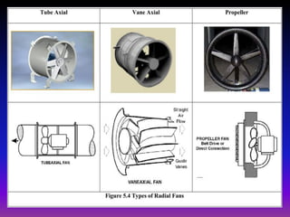
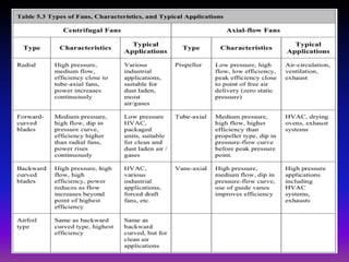
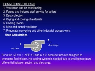
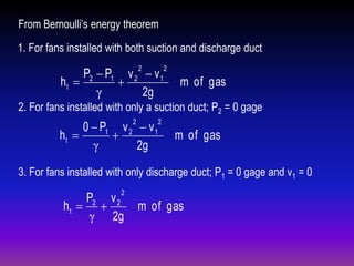
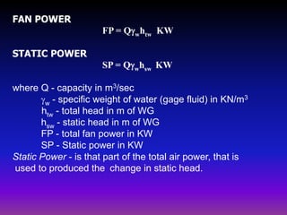
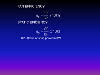
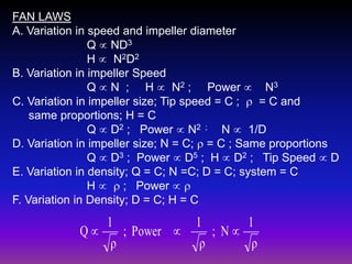
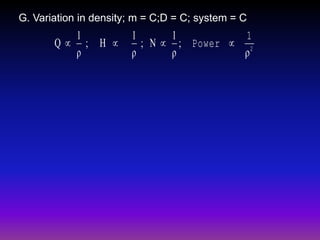


This document summarizes information about fans and blowers. It defines fans and blowers, describes common types of fans including axial and centrifugal fans. It discusses fan performance parameters such as pressure, flow rate, power and efficiency. The document also presents relationships called fan laws that describe how these parameters change with speed, size and other variables. Formulas are provided for calculating pressure, power and efficiency. Common applications of fans are also listed.


![[W f stoecker]_refrigeration_and_a_ir_conditioning_(book_zz.org)](https://cdn.slidesharecdn.com/ss_thumbnails/wfstoeckerrefrigerationandairconditioningbookzz-161019162540-thumbnail.jpg?width=640&height=640&fit=bounds)