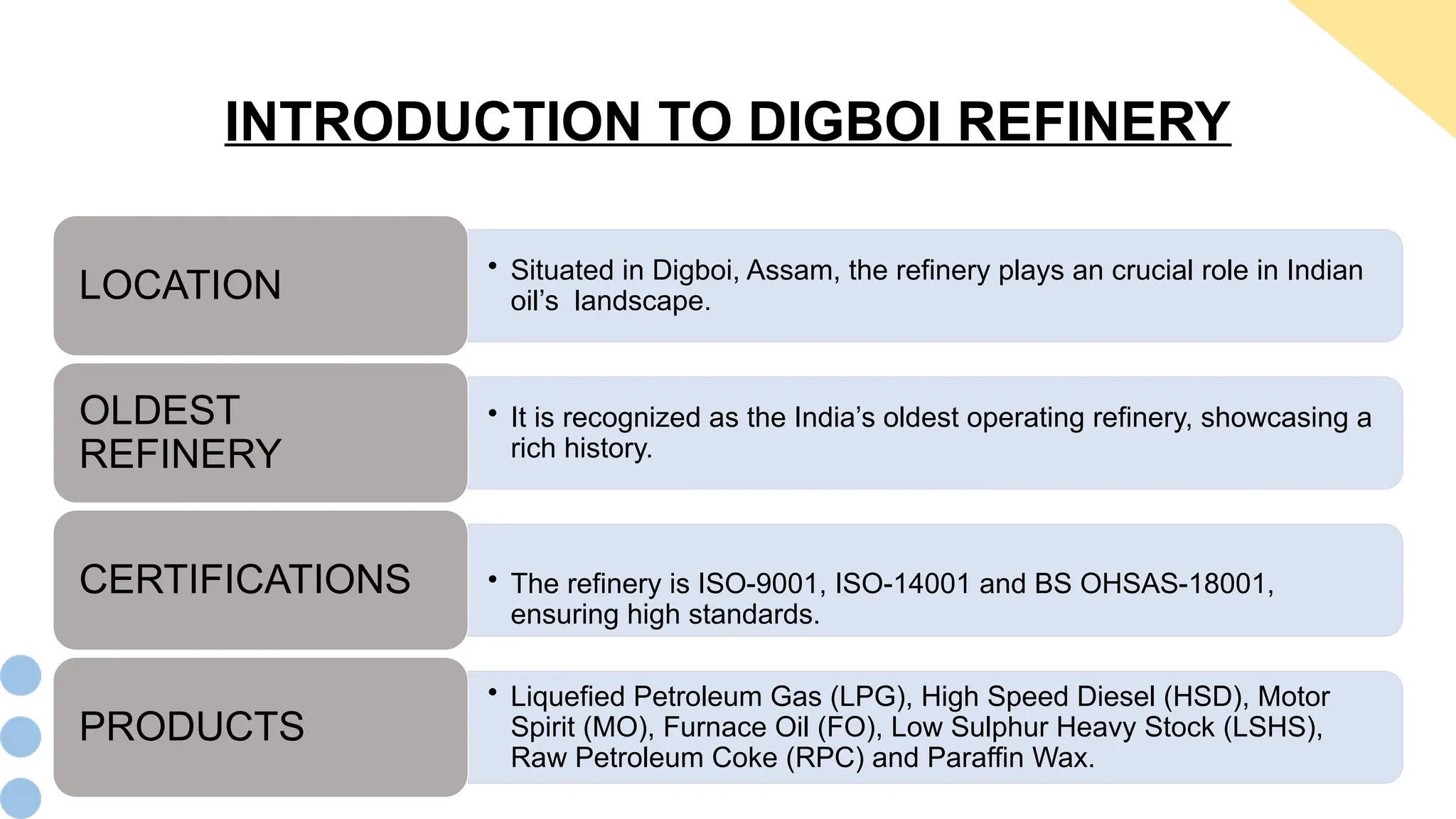
MECHANICAL MAINTENANCE
IOCL, DIGBOI
Presented By:
Kamal Das (212310002028)
Kalyan Jyoti Baruah (212310002027)
Trideep Kurmi(222350002004)
Department of Mechanical Engineering
Golaghat Engineering College, Golaghat, Assam
CONTENTS
o Introduction to Digboi Refinery
o Fire and Safety
o Mechanical Maintenance and its Units
o Captive Power Plant
o Wax Sector
o Hydro-treater Block
o Fuel Sector
o Conclusion
• Situated in Digboi, Assam, the refinery plays an crucial role in Indian
oil’s landscape.
LOCATION
• It is recognized as the India’s oldest operating refinery, showcasing a
rich history.
OLDEST
REFINERY
• The refinery is ISO-9001, ISO-14001 and BS OHSAS-18001,
ensuring high standards.
CERTIFICATIONS
• Liquefied Petroleum Gas (LPG), High Speed Diesel (HSD), Motor
Spirit (MO), Furnace Oil (FO), Low Sulphur Heavy Stock (LSHS),
Raw Petroleum Coke (RPC) and Paraffin Wax.
PRODUCTS
INTRODUCTION TO DIGBOI REFINERY
Fire and Safety
Training
• Regular training sessions for
employees enhance
awareness and
preparedness for
emergency situation.
Mandatory Safety
Pass
• Access to battery areas
requires mandatory safety
passes, ensuring only
trained personnel to enter
the hazardous zone.
Fire Alarms
• Fire alarms are strategically
installed throughout the
facility for immediate access
in emergencies.
Personal Protective
Equipment (PPE)
• Utilization of PPE is
enforced to minimize the risk
and protect employees from
hazards.
Prohibition Of
Inflammable Objects
• Strict rules against the
presence of inflammable
materials in battery areas to
prevent fire hazard.
FIRE AND SAFETY
Captive
Power Plant
Wax Sector
Hydro-treater
Block
Fuel Sector
MECHANICAL MAINTENANCE
 Mechanical maintenance involves planned and unplanned activities to inspect, repair, replace and
modify mechanical components, equipment's and system to maintain productivity, efficiency and
safety in industrial setting.
KEY UNITS OF MECHANINAL MAINTENANCE
 Objective of Gas Turbine Generator
Schematic Diagram For Gas Turbine Generator
Components of Gas Turbine Generator:
Diesel Engine
 Accessories Gear Box
 Torque Converter
 Fuel Pump
Atomizing Air Compressor
Combustion Chamber
Turbine
Speed Reduction Gear Box
Generator Flow-Chart Of Gas Turbine Generator in IOCL, Digboi
Diesel Engine Gear Box Compressor Turbine Gear Box
Generator/
Coupling
Combustion
Chamber
Combustion
Chamber
• Captive Power Plant
Drift eliminators remove water droplets from exhaust air.
Cooled water collects in distribution basin.
Heat transfer occurs between water and air, cooling the water
Fan creates induced draft, pulling air through the tower.
Air enters the tower through louvers, creating a counter flow to
water.
Water distributed through spray nozzles, creating a uniform
spray pattern
Hot water from process cooling systems is pumped to the top
of the tower
WORKING PRINCIPLE:
Induced Draft Cooling Tower
• Cooling Tower: Induced Draft Cooling Tower
• De-Mineralization Water Plant
De-Mineralization Water Plant
Typical refining scheme for paraffinic wax production
 Paraffin wax production has been handled by
Digboi refinery since the 1950s.
Three types of wax are produced:
• Food/Pharmaceutical Grade (Type 1) is considered
one of the best waxes in the world.
• Candle/Sealant Wax (Type 2 & 2A) is used for
candles, polishes, and artifacts.
• Non-Critical Wax (Type 3) is used in match and
tarpaulin industries.
WAX SECTOR
• Solvent Dewaxing / De-Oiling Unit
 The old wax extraction system was replaced by the Solvent Dewaxing Unit to improve quality and
production.
 Wax production was increased from 33,000 TPA to 49,000 TPA.
 An additional 11,000 TPA of microcrystalline wax can be produced.
Rotary Drum Filter
Key Equipment Includes:
• The Rotary Vacuum Drum Filter, which is used to filter wax and
oil.
• Chillers, where wax is cooled and crystallized during production.
• Wax Hydro-Finishing Unit
• The wax is refined through desulfurization and stabilization to improve its quality.
• Hydro-Finishing is carried out by hydrogenating the wax in the presence of a catalyst.
• Wax Pelletization Unit
• The Wax Pelletization Unit was introduced to convert liquid wax into solid pellet form.
Melting and
Filtration
• Liquid wax is
heated to its
melting point and
filtered to remove
impurities.
Pelletization
• The liquid wax is
sprayed into a
cooling chamber,
where it solidifies
into small pellets.
Cooling
• Wax pellets are
cooled quickly
using water cooling
systems with belts
and conveyors to
maintain shape and
quality.
Screening and
Packaging
• Pellets are
screened for
uniform size and
then packed into
bags or containers
for shipment.
HYDRO-TREATER BLOCK
Units Included:
• Amine Treating Unit (ATU), where H2S and CO2 are
removed from gas streams.
• Amine Recovery Unit (ARU), where the amine is recycled
after H2S removal.
• Wild Naphtha Stabilization, in which lighter hydrocarbons are
removed from the naphtha stream. Classification of Hydro-Treater Block
 Products such as low sulfur HSD and high smoke-point kerosene are produced.
 The Hydro-treater Block is used to remove contaminants such as sulfur and nitrogen.
• Sulfur Recovery Unit
 The Claus process is used to convert hydrogen sulfide (H2S) into sulfur.
Main Components Include:
• The Reaction Furnace, where H2S is burned to form sulfur dioxide.
• Catalytic Converters, where sulfur dioxide is converted into elemental sulfur.
• The process is used to meet environmental standards and prevent pollution.
• Hydrogen Generating Unit
 Hydrogen is generated to assist in the desulfurization of refinery products.
 Hydrogen is produced with 99.9% purity for refining purposes.
The Process Involves:
• Feed Treatment.
• High-Temperature Shift Reaction.
• Product Purification using the PSA Unit.
Flow Chart Of Hydrogen Generating Unit
• The fuel sector in a refinery refers to the processing and production of various
fuels.
Fuels From The Refinery: Gasoline (Petrol), Diesel, Jet Fuel, Liquefied Petroleum Gas, Naphtha,
Kerosene, Atmospheric Gas Oil and Vacuum Gas Oil.
DIFFERENT UNITS OF FUEL SECTOR
Atmospheric and Vacuum
Distillation Unit (AVU)
Catalytic Reforming Unit
(CRU)
Delayed Coking Unit (DCU)
FUEL SECTOR
• Atmospheric and Vacuum Unit (AVU)
Flow Chart of Atmospheric and Vacuum Unit
PROCESS OBJECTIVE:
• To distill and separate valuable distillates (naphtha, kerosene, diesel) and atmospheric gas oil (AGO)
from the crude feedstock.
• To recover valuable gas oils from reduced crude via vacuum distillation.
Condensation
Re-boiling
Product Withdrawl
Reflux
Separation
Feed Introduction
WORKING OF ATMOSPHERIC AND VACUUM
TOWER
• Catalytic Reforming Unit
PROCESS OBJECTIVE:
 To convert low-octane naphtha into a high-octane reformate for gasoline blending.
 Reforming also produces high purity hydrogen for hydro-treating process.
Mechanical Equipment's Used:
• Reformer Reactor Converts naphtha into reformate.
• Catalyst Regeneration Vessel Regenerates catalyst (Palladium or Platinum).
• Hydrogen Reactor Removes impurities (Unsaturated Hydrocarbons).
• Separator Vessels Separates gas-liquid, liquid-liquid.
Output Products:
• Main Products: Reformate, Hydrogen Gas
• By products: LPG, Aromatics, Fuel Gas and others.
Feed
(Preheated)
Reformer
Reactor
and Cooler
Hydrogen
Reactor
Gas-Liquid
Separator
Stabilizer
Hydrogen
Recovery
Product
Storage
• The DCU is a refining process unit that converts heavy, complex hydrocarbons into lighter, more
valuable products.
MAIN FUNCTIONS
• Delayed Coking Unit
• Breaks down heavy residues into lighter hydrocarbons.
Thermal Cracking
• Converts heavy residues into petroleum coke and liquid
products.
Coking
• Separates gasoline, diesel, LPG, fuel gas and petroleum
coke.
Product Separation
• Upgrades product quality to meet regulatory standards.
Quality Enhancement
• Main Products: Gasoline, Diesel, LPG, Fuel Gas and Petroleum Coke.
• By-products: Naphtha, Kerosene, Jet Fuel, Atmospheric Gas Oil and Vacuum Gas Oil.
CONCLUSION
• Our 30 day industrial internship in IOCL Digboi Mechanical Maintenance units was a
transformative experience that provided invaluable insights into the refining industry.
Here are the Key Takeaways:
Practical
Exposure
• Applied
theoretical
knowledge to
real world
problems.
Industry
Insights
• Gain
understanding
of refinery
operations.
Technical Skills
• Developed
skills in
equipment
maintenance
and repair.
Safety
Protocols
• Learned
importance of
workplace
safety.
Career
Readiness
• Prepared for a
career in
mechanical
maintenance.
Thank You

Industrial Internship ppt at digboi IOCL

  • 1.
    MECHANICAL MAINTENANCE IOCL, DIGBOI PresentedBy: Kamal Das (212310002028) Kalyan Jyoti Baruah (212310002027) Trideep Kurmi(222350002004) Department of Mechanical Engineering Golaghat Engineering College, Golaghat, Assam
  • 2.
    CONTENTS o Introduction toDigboi Refinery o Fire and Safety o Mechanical Maintenance and its Units o Captive Power Plant o Wax Sector o Hydro-treater Block o Fuel Sector o Conclusion
  • 3.
    • Situated inDigboi, Assam, the refinery plays an crucial role in Indian oil’s landscape. LOCATION • It is recognized as the India’s oldest operating refinery, showcasing a rich history. OLDEST REFINERY • The refinery is ISO-9001, ISO-14001 and BS OHSAS-18001, ensuring high standards. CERTIFICATIONS • Liquefied Petroleum Gas (LPG), High Speed Diesel (HSD), Motor Spirit (MO), Furnace Oil (FO), Low Sulphur Heavy Stock (LSHS), Raw Petroleum Coke (RPC) and Paraffin Wax. PRODUCTS INTRODUCTION TO DIGBOI REFINERY
  • 4.
    Fire and Safety Training •Regular training sessions for employees enhance awareness and preparedness for emergency situation. Mandatory Safety Pass • Access to battery areas requires mandatory safety passes, ensuring only trained personnel to enter the hazardous zone. Fire Alarms • Fire alarms are strategically installed throughout the facility for immediate access in emergencies. Personal Protective Equipment (PPE) • Utilization of PPE is enforced to minimize the risk and protect employees from hazards. Prohibition Of Inflammable Objects • Strict rules against the presence of inflammable materials in battery areas to prevent fire hazard. FIRE AND SAFETY
  • 5.
    Captive Power Plant Wax Sector Hydro-treater Block FuelSector MECHANICAL MAINTENANCE  Mechanical maintenance involves planned and unplanned activities to inspect, repair, replace and modify mechanical components, equipment's and system to maintain productivity, efficiency and safety in industrial setting. KEY UNITS OF MECHANINAL MAINTENANCE
  • 6.
     Objective ofGas Turbine Generator Schematic Diagram For Gas Turbine Generator Components of Gas Turbine Generator: Diesel Engine  Accessories Gear Box  Torque Converter  Fuel Pump Atomizing Air Compressor Combustion Chamber Turbine Speed Reduction Gear Box Generator Flow-Chart Of Gas Turbine Generator in IOCL, Digboi Diesel Engine Gear Box Compressor Turbine Gear Box Generator/ Coupling Combustion Chamber Combustion Chamber • Captive Power Plant
  • 7.
    Drift eliminators removewater droplets from exhaust air. Cooled water collects in distribution basin. Heat transfer occurs between water and air, cooling the water Fan creates induced draft, pulling air through the tower. Air enters the tower through louvers, creating a counter flow to water. Water distributed through spray nozzles, creating a uniform spray pattern Hot water from process cooling systems is pumped to the top of the tower WORKING PRINCIPLE: Induced Draft Cooling Tower • Cooling Tower: Induced Draft Cooling Tower
  • 8.
    • De-Mineralization WaterPlant De-Mineralization Water Plant
  • 9.
    Typical refining schemefor paraffinic wax production  Paraffin wax production has been handled by Digboi refinery since the 1950s. Three types of wax are produced: • Food/Pharmaceutical Grade (Type 1) is considered one of the best waxes in the world. • Candle/Sealant Wax (Type 2 & 2A) is used for candles, polishes, and artifacts. • Non-Critical Wax (Type 3) is used in match and tarpaulin industries. WAX SECTOR
  • 10.
    • Solvent Dewaxing/ De-Oiling Unit  The old wax extraction system was replaced by the Solvent Dewaxing Unit to improve quality and production.  Wax production was increased from 33,000 TPA to 49,000 TPA.  An additional 11,000 TPA of microcrystalline wax can be produced. Rotary Drum Filter Key Equipment Includes: • The Rotary Vacuum Drum Filter, which is used to filter wax and oil. • Chillers, where wax is cooled and crystallized during production.
  • 11.
    • Wax Hydro-FinishingUnit • The wax is refined through desulfurization and stabilization to improve its quality. • Hydro-Finishing is carried out by hydrogenating the wax in the presence of a catalyst. • Wax Pelletization Unit • The Wax Pelletization Unit was introduced to convert liquid wax into solid pellet form. Melting and Filtration • Liquid wax is heated to its melting point and filtered to remove impurities. Pelletization • The liquid wax is sprayed into a cooling chamber, where it solidifies into small pellets. Cooling • Wax pellets are cooled quickly using water cooling systems with belts and conveyors to maintain shape and quality. Screening and Packaging • Pellets are screened for uniform size and then packed into bags or containers for shipment.
  • 12.
    HYDRO-TREATER BLOCK Units Included: •Amine Treating Unit (ATU), where H2S and CO2 are removed from gas streams. • Amine Recovery Unit (ARU), where the amine is recycled after H2S removal. • Wild Naphtha Stabilization, in which lighter hydrocarbons are removed from the naphtha stream. Classification of Hydro-Treater Block  Products such as low sulfur HSD and high smoke-point kerosene are produced.  The Hydro-treater Block is used to remove contaminants such as sulfur and nitrogen.
  • 13.
    • Sulfur RecoveryUnit  The Claus process is used to convert hydrogen sulfide (H2S) into sulfur. Main Components Include: • The Reaction Furnace, where H2S is burned to form sulfur dioxide. • Catalytic Converters, where sulfur dioxide is converted into elemental sulfur. • The process is used to meet environmental standards and prevent pollution.
  • 14.
    • Hydrogen GeneratingUnit  Hydrogen is generated to assist in the desulfurization of refinery products.  Hydrogen is produced with 99.9% purity for refining purposes. The Process Involves: • Feed Treatment. • High-Temperature Shift Reaction. • Product Purification using the PSA Unit. Flow Chart Of Hydrogen Generating Unit
  • 15.
    • The fuelsector in a refinery refers to the processing and production of various fuels. Fuels From The Refinery: Gasoline (Petrol), Diesel, Jet Fuel, Liquefied Petroleum Gas, Naphtha, Kerosene, Atmospheric Gas Oil and Vacuum Gas Oil. DIFFERENT UNITS OF FUEL SECTOR Atmospheric and Vacuum Distillation Unit (AVU) Catalytic Reforming Unit (CRU) Delayed Coking Unit (DCU) FUEL SECTOR
  • 16.
    • Atmospheric andVacuum Unit (AVU) Flow Chart of Atmospheric and Vacuum Unit PROCESS OBJECTIVE: • To distill and separate valuable distillates (naphtha, kerosene, diesel) and atmospheric gas oil (AGO) from the crude feedstock. • To recover valuable gas oils from reduced crude via vacuum distillation. Condensation Re-boiling Product Withdrawl Reflux Separation Feed Introduction WORKING OF ATMOSPHERIC AND VACUUM TOWER
  • 17.
    • Catalytic ReformingUnit PROCESS OBJECTIVE:  To convert low-octane naphtha into a high-octane reformate for gasoline blending.  Reforming also produces high purity hydrogen for hydro-treating process. Mechanical Equipment's Used: • Reformer Reactor Converts naphtha into reformate. • Catalyst Regeneration Vessel Regenerates catalyst (Palladium or Platinum). • Hydrogen Reactor Removes impurities (Unsaturated Hydrocarbons). • Separator Vessels Separates gas-liquid, liquid-liquid. Output Products: • Main Products: Reformate, Hydrogen Gas • By products: LPG, Aromatics, Fuel Gas and others. Feed (Preheated) Reformer Reactor and Cooler Hydrogen Reactor Gas-Liquid Separator Stabilizer Hydrogen Recovery Product Storage
  • 18.
    • The DCUis a refining process unit that converts heavy, complex hydrocarbons into lighter, more valuable products. MAIN FUNCTIONS • Delayed Coking Unit • Breaks down heavy residues into lighter hydrocarbons. Thermal Cracking • Converts heavy residues into petroleum coke and liquid products. Coking • Separates gasoline, diesel, LPG, fuel gas and petroleum coke. Product Separation • Upgrades product quality to meet regulatory standards. Quality Enhancement • Main Products: Gasoline, Diesel, LPG, Fuel Gas and Petroleum Coke. • By-products: Naphtha, Kerosene, Jet Fuel, Atmospheric Gas Oil and Vacuum Gas Oil.
  • 19.
    CONCLUSION • Our 30day industrial internship in IOCL Digboi Mechanical Maintenance units was a transformative experience that provided invaluable insights into the refining industry. Here are the Key Takeaways: Practical Exposure • Applied theoretical knowledge to real world problems. Industry Insights • Gain understanding of refinery operations. Technical Skills • Developed skills in equipment maintenance and repair. Safety Protocols • Learned importance of workplace safety. Career Readiness • Prepared for a career in mechanical maintenance.
  • 20.