The document outlines the petroleum refining process, highlighting its significance in providing fuels for transportation and the impact of fluctuating crude oil prices on innovation in cleaner fuel production and refining techniques. It details various processes including physical separation, catalytic conversion, and thermal chemical conversion, describing methods such as crude distillation, catalytic reforming, and coking to produce valuable refined products. Additionally, it emphasizes advancements aimed at meeting stricter environmental regulations and reducing costs in fuel production.
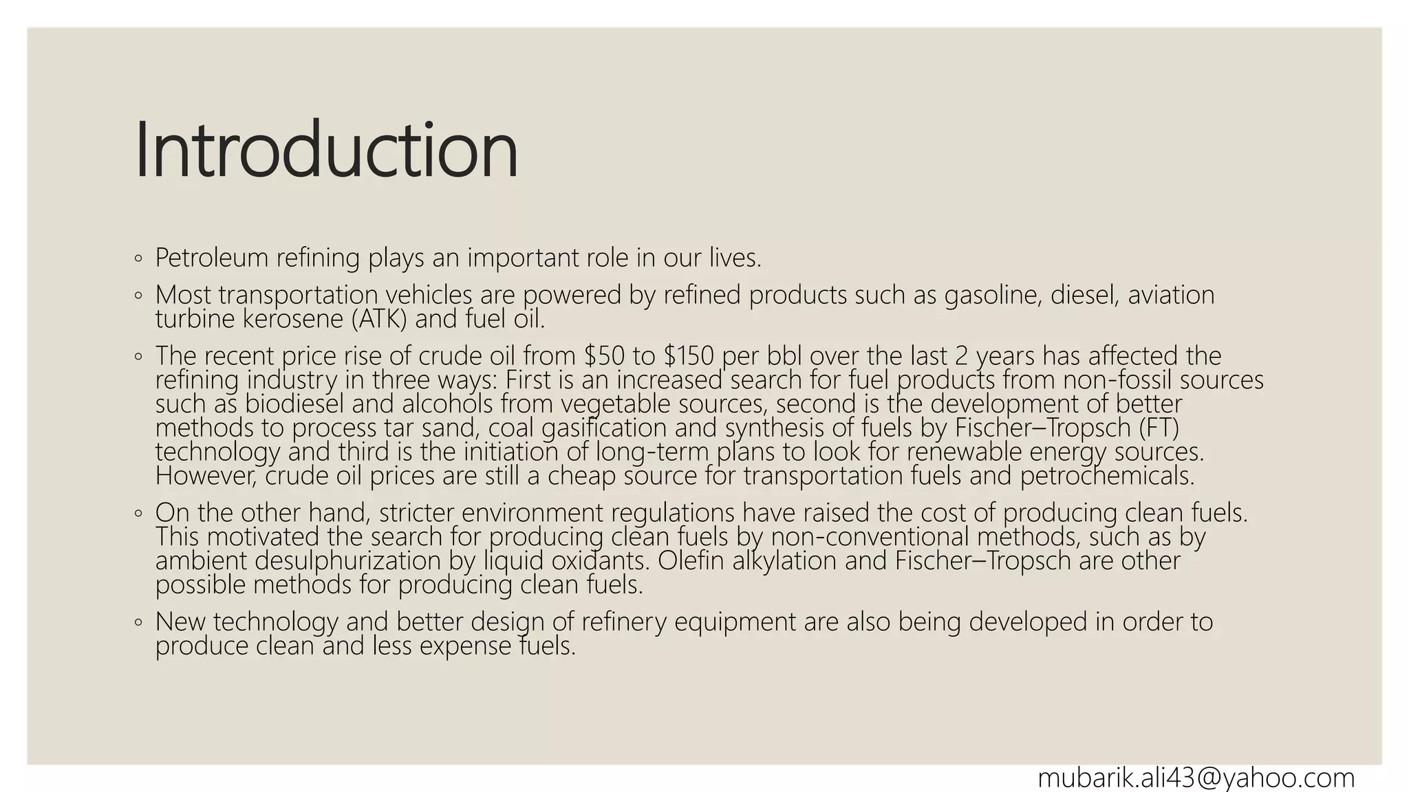
Introduction to petroleum refining's impact on transportation, price fluctuations, and clean fuel technologies.
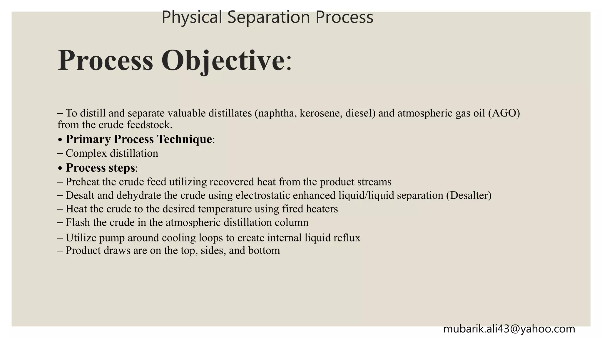
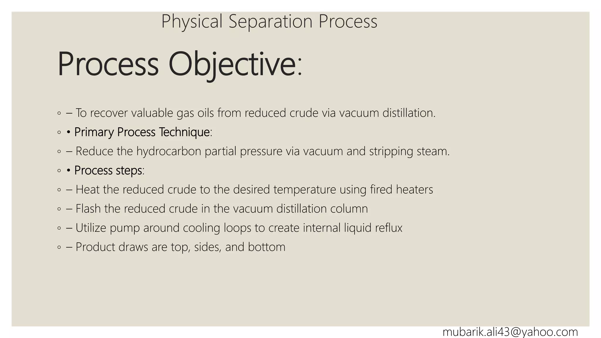
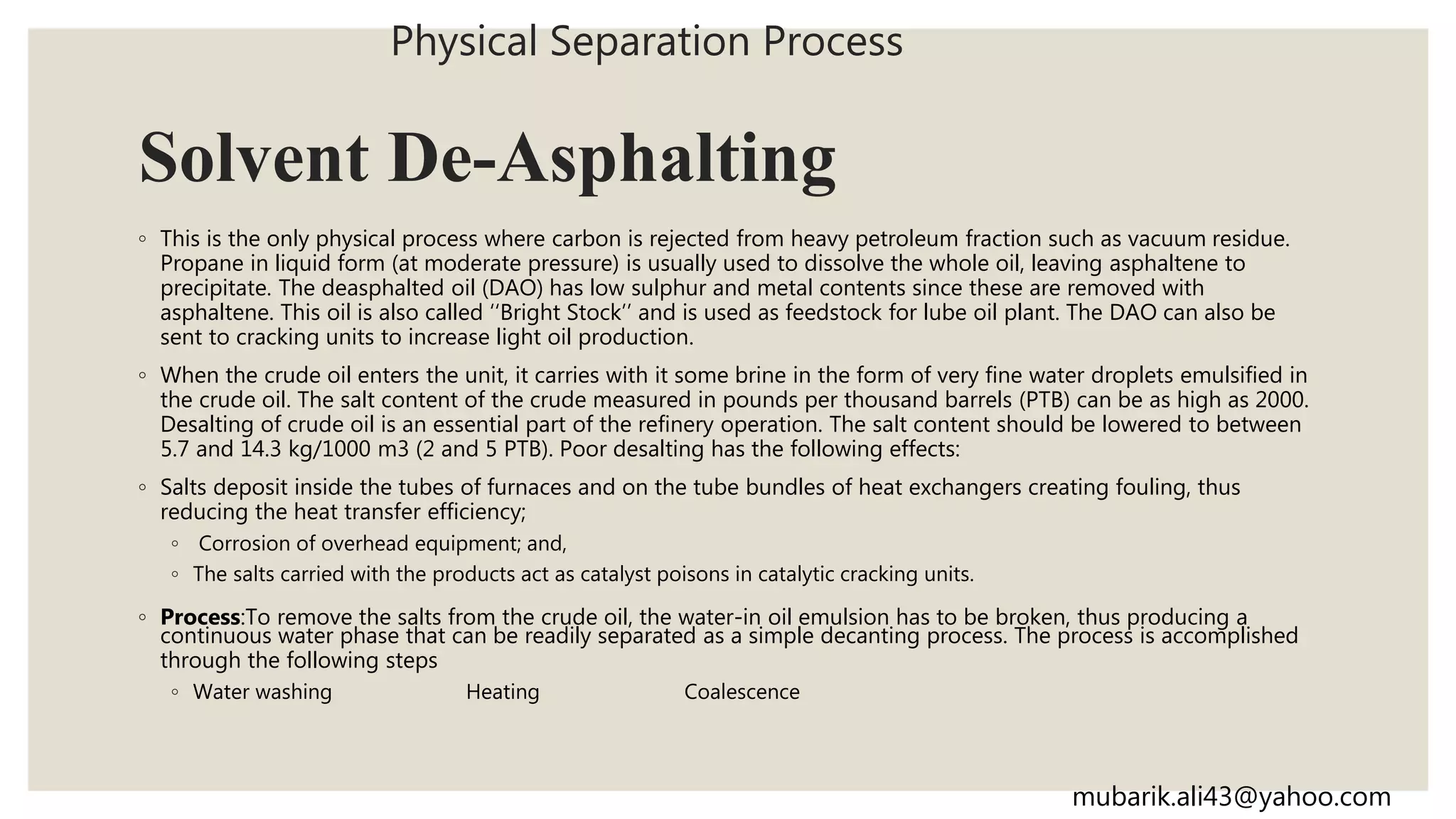
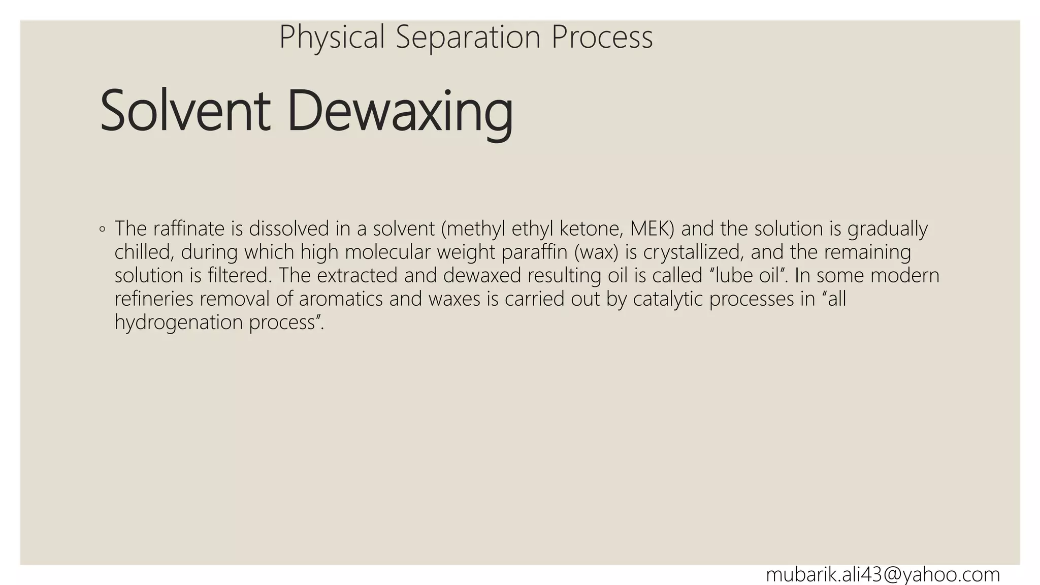
Physical separation processes including crude distillation, vacuum distillation, solvent extraction, and dewaxing to separate valuable products from crude oil.
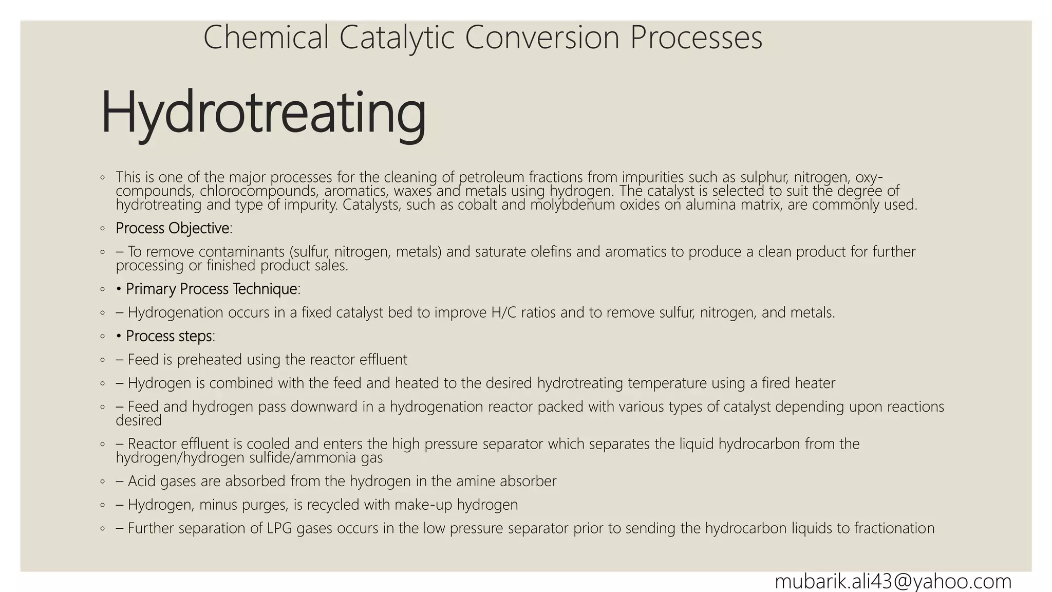
Chemical processes like catalytic reforming and hydrocracking that convert low-value oils into valuable products and improve fuel quality.
Processes such as coking and visbreaking that upgrade heavy residues into lighter products while addressing sulfur content.
Introduction
◦ Petroleum refiningplays an important role in our lives.
◦ Most transportation vehicles are powered by refined products such as gasoline, diesel, aviation
turbine kerosene (ATK) and fuel oil.
◦ The recent price rise of crude oil from $50 to $150 per bbl over the last 2 years has affected the
refining industry in three ways: First is an increased search for fuel products from non-fossil sources
such as biodiesel and alcohols from vegetable sources, second is the development of better
methods to process tar sand, coal gasification and synthesis of fuels by Fischer–Tropsch (FT)
technology and third is the initiation of long-term plans to look for renewable energy sources.
However, crude oil prices are still a cheap source for transportation fuels and petrochemicals.
◦ On the other hand, stricter environment regulations have raised the cost of producing clean fuels.
This motivated the search for producing clean fuels by non-conventional methods, such as by
ambient desulphurization by liquid oxidants. Olefin alkylation and Fischer–Tropsch are other
possible methods for producing clean fuels.
◦ New technology and better design of refinery equipment are also being developed in order to
produce clean and less expense fuels.
mubarik.ali43@yahoo.com
3.
Refining Processes
Physical Separation
Process
•Crude Distillation
Chemical Catalytic
Conversion Processes
• Catalytic Reforming
Thermal Chemical
Conversion Processes
• Coking
mubarik.ali43@yahoo.com
4.
Crude Distillation unit(CDU)
Crude oils are first desalted and then introduced
with steam to an atmospheric distillation column.
The atmospheric residue is then introduced to a
vacuum distillation tower operating at about 50
mmHg, where heavier products are obtained.
Typical products from both columns and their
boiling point ranges are listed in Table 1.2.
Table 1.2
Physical Separation Process
mubarik.ali43@yahoo.com
5.
Process Objective:
– Todistill and separate valuable distillates (naphtha, kerosene, diesel) and atmospheric gas oil (AGO)
from the crude feedstock.
• Primary Process Technique:
– Complex distillation
• Process steps:
– Preheat the crude feed utilizing recovered heat from the product streams
– Desalt and dehydrate the crude using electrostatic enhanced liquid/liquid separation (Desalter)
– Heat the crude to the desired temperature using fired heaters
– Flash the crude in the atmospheric distillation column
– Utilize pump around cooling loops to create internal liquid reflux
– Product draws are on the top, sides, and bottom
Physical Separation Process
mubarik.ali43@yahoo.com
6.
Vacuum Distillation Unit(VDU)
◦ To extract more distillates from the atmospheric residue, the bottom from the
atmospheric CDU is sent to the vacuum distillation unit.
◦ The vacuum unit distillates are classified as light vacuum gas oil (LVGO), medium
vacuum gas oil (MVGO), and heavy vacuum gas oil (HVGO). In addition a vacuum
residue is produced. If the distillates are feed to downstream conversion process,
their sulphur, metal and asphaltene content should be reduced by hydrotreating
or hydroprocessing.
◦ In some refineries the whole atmospheric residue is hydroprocessed before
vacuum distillation. The vacuum unit can also be used to produce lubrication oil
grade feed stocks. This depends on the quality of the crude oil feed to the refinery
as only special types of crude can produce lube grade feed stocks.
Physical Separation Process
mubarik.ali43@yahoo.com
7.
Process Objective:
◦ –To recover valuable gas oils from reduced crude via vacuum distillation.
◦ • Primary Process Technique:
◦ – Reduce the hydrocarbon partial pressure via vacuum and stripping steam.
◦ • Process steps:
◦ – Heat the reduced crude to the desired temperature using fired heaters
◦ – Flash the reduced crude in the vacuum distillation column
◦ – Utilize pump around cooling loops to create internal liquid reflux
◦ – Product draws are top, sides, and bottom
Physical Separation Process
mubarik.ali43@yahoo.com
8.
Solvent De-Asphalting
◦ Thisis the only physical process where carbon is rejected from heavy petroleum fraction such as vacuum residue.
Propane in liquid form (at moderate pressure) is usually used to dissolve the whole oil, leaving asphaltene to
precipitate. The deasphalted oil (DAO) has low sulphur and metal contents since these are removed with
asphaltene. This oil is also called ‘‘Bright Stock’’ and is used as feedstock for lube oil plant. The DAO can also be
sent to cracking units to increase light oil production.
◦ When the crude oil enters the unit, it carries with it some brine in the form of very fine water droplets emulsified in
the crude oil. The salt content of the crude measured in pounds per thousand barrels (PTB) can be as high as 2000.
Desalting of crude oil is an essential part of the refinery operation. The salt content should be lowered to between
5.7 and 14.3 kg/1000 m3 (2 and 5 PTB). Poor desalting has the following effects:
◦ Salts deposit inside the tubes of furnaces and on the tube bundles of heat exchangers creating fouling, thus
reducing the heat transfer efficiency;
◦ Corrosion of overhead equipment; and,
◦ The salts carried with the products act as catalyst poisons in catalytic cracking units.
◦ Process:To remove the salts from the crude oil, the water-in oil emulsion has to be broken, thus producing a
continuous water phase that can be readily separated as a simple decanting process. The process is accomplished
through the following steps
◦ Water washing Heating Coalescence
Physical Separation Process
mubarik.ali43@yahoo.com
9.
Solvent Extraction
◦ Inthis process, lube oil stock is treated by a solvent, such as N-methyl pyrrolidone (NMP),
which can dissolve the aromatic components in one phase (extract) and the rest of the oil in
another phase (raffinate). The solvent is removed from both phases and the raffinate is
dewaxed.
Physical Separation Process
mubarik.ali43@yahoo.com
10.
Solvent Dewaxing
◦ Theraffinate is dissolved in a solvent (methyl ethyl ketone, MEK) and the solution is gradually
chilled, during which high molecular weight paraffin (wax) is crystallized, and the remaining
solution is filtered. The extracted and dewaxed resulting oil is called ‘‘lube oil’’. In some modern
refineries removal of aromatics and waxes is carried out by catalytic processes in ‘‘all
hydrogenation process’’.
Physical Separation Process
mubarik.ali43@yahoo.com
11.
Chemical Catalytic ConversionProcesses
◦ In this process a special catalyst (platinum metal supported on silica or silica base alumina) is used to restructure
naphtha fraction (C6–C10) into aromatics and isoparaffins. The produced naphtha reformate has a much higher
octane number than the feed. This reformate is used in gasoline formulation and as a feedstock for aromatic
production (benzene–toluene–xylene, BTX).
◦ Process Objective:
◦ – To convert low-octane naphtha into a high-octane reformate for gasoline blending and/or to provide aromatics
(benzene, toluene, and xylene) for petrochemical plants. Reforming also produces high purity hydrogen for
hydrotreating processes.
◦ • Primary Process Technique:
◦ – Reforming reactions occur in chloride promoted fixed catalyst beds; or continuous catalyst regeneration (CCR)
beds where the catalyst is transferred from one stage to another, through a catalyst regenerator and back again.
Desired reactions include: dehydrogenation of naphthenes to form aromatics; isomerization of naphthenes;
dehydrocyclization of paraffins to form aromatics; and isomerization of paraffins. Hydrocracking of paraffins is
undesirable due to increased light-ends make.
◦ • Process steps:
◦ – Naphtha feed and recycle hydrogen are mixed, heated and sent through successive reactor beds
◦ – Each pass requires heat input to drive the reactions
◦ – Final pass effluent is separated with the hydrogen being recycled or purged for hydrotreating
◦ – Reformate product can be further processed to separate aromatic components or be used for gasoline blending.
Catalytic Reforming
mubarik.ali43@yahoo.com
12.
Hydrotreating
◦ This isone of the major processes for the cleaning of petroleum fractions from impurities such as sulphur, nitrogen, oxy-
compounds, chlorocompounds, aromatics, waxes and metals using hydrogen. The catalyst is selected to suit the degree of
hydrotreating and type of impurity. Catalysts, such as cobalt and molybdenum oxides on alumina matrix, are commonly used.
◦ Process Objective:
◦ – To remove contaminants (sulfur, nitrogen, metals) and saturate olefins and aromatics to produce a clean product for further
processing or finished product sales.
◦ • Primary Process Technique:
◦ – Hydrogenation occurs in a fixed catalyst bed to improve H/C ratios and to remove sulfur, nitrogen, and metals.
◦ • Process steps:
◦ – Feed is preheated using the reactor effluent
◦ – Hydrogen is combined with the feed and heated to the desired hydrotreating temperature using a fired heater
◦ – Feed and hydrogen pass downward in a hydrogenation reactor packed with various types of catalyst depending upon reactions
desired
◦ – Reactor effluent is cooled and enters the high pressure separator which separates the liquid hydrocarbon from the
hydrogen/hydrogen sulfide/ammonia gas
◦ – Acid gases are absorbed from the hydrogen in the amine absorber
◦ – Hydrogen, minus purges, is recycled with make-up hydrogen
◦ – Further separation of LPG gases occurs in the low pressure separator prior to sending the hydrocarbon liquids to fractionation
Chemical Catalytic Conversion Processes
mubarik.ali43@yahoo.com
13.
Catalytic Hydrocracking
◦ Forhigher molecular weight fractions such as atmospheric residues (AR) and vacuum gas oils (VGOs), cracking in the
presence of hydrogen is required to get light products. In this case a dual function catalyst is used. It is composed of a
zeolite catalyst for the cracking function and rare earth metals supported on alumina for the hydrogenation function.
The main products are kerosene, jet fuel, diesel and fuel oil.
◦ Process Objective:
◦ – To remove feed contaminants (nitrogen, sulfur, metals) and to convert low value gas oils to valuable products (naphtha,
middle distillates, and ultra-clean lube base stocks).
◦ • Primary Process Technique:
◦ – Hydrogenation occurs in fixed hydrotreating catalyst beds to improve H/C ratios and to remove sulfur, nitrogen, and
metals. This is followed by one or more reactors with fixed hydrocracking catalyst beds to dealkylate aromatic rings, open
naphthene rings, and hydrocrack paraffin chains.
◦ • Process steps:
◦ – Preheated feed is mixed with hot hydrogen and passes through a multi-bed reactor with interstage hydrogen
quenches for hydrotreating
◦ – Hydrotreated feed is mixed with additional hot hydrogen and passes through a multi-bed reactor with quenches for
first pass hydrocracking
◦ – Reactor effluents are combined and pass through high and low pressure separators and are fed to the fractionator
where valuable products are drawn from the top, sides, and bottom
◦ – Fractionator bottoms may be recycled to a second pass hydrocracker for additional conversion all the way up to full
conversion.
Chemical Catalytic Conversion Processes
mubarik.ali43@yahoo.com
14.
Catalytic Cracking
◦ Fluidcatalytic cracking (FCC) is the main player for the production of gasoline. The catalyst in this
case is a zeolite base for the cracking function. The main feed to FCC is VGO and the product is
gasoline, but some gas oil and refinery gases are also produced.
◦ Process Objective:
◦ – To convert low value gas oils to valuable products (naphtha and diesel) and slurry oil.
◦ • Primary Process Technique:
◦ – Catalytic cracking increases H/C ratio by carbon rejection in a continuous process.
◦ • Process steps:
◦ – Gas oil feed is dispersed into the bottom of the riser using steam
◦ – Thermal cracking occurs on the surface of the catalyst
◦ – Disengaging drum separates spent catalyst from product vapors
◦ – Steam strips residue hydrocarbons from spent catalyst
◦ – Air burns away the carbon film from the catalyst in either a
◦ “partial-burn” or “full-burn” mode of operation
◦ – Regenerated catalyst enters bottom of riser-reactor
Chemical Catalytic Conversion Processes
mubarik.ali43@yahoo.com
15.
Alkylation
◦ Alkylation isthe process in which isobutane reacts with olefins such as butylene (C
◦ ¼ 4 ) to produce a gasoline range alkylate. The catalyst in this case is either sulphuric acid or hydrofluoric acid. The
hydrocarbons and acid react in liquid phase. Isobutane and olefins are collected mainly from FCC and delayed coker.
◦ Process Objective:
◦ – To combine light olefins (propylene and butylene) with isobutane to form a high octane gasoline (alkylate).
◦ • Primary Process Technique:
◦ – Alkylation occurs in the presence of a highly acidic catalyst (hydroflouric acid or sulfuric acid).
◦
◦ • Process steps:
◦ – Olefins from FCC are combined with IsoButane and fed to the HF Reactor where alkylation occurs
◦ – Acid settler separates the free HF from the hydrocarbons and recycles the acid back to the reactor
◦ – A portion of the HF is regenerated to remove acid oils formed by feed contaminants or hydrocarbon polymerization
◦ – Hydrocarbons from settler go to the DeIsobutanizer for fractionating the propane and isobutane from the n-butane
and alkylate
◦ – Propane is then fractionated from the isobutane; propane as a product and the isobutane to be recycled to the reactor
◦ – N-Butane and alkylate are deflourinated in a bed of solid adsorbent and fractionated as separate products.
Chemical Catalytic Conversion Processes
mubarik.ali43@yahoo.com
16.
Isomerization
◦ Isomerization oflight naphtha is the process in which low octane number hydrocarbons (C4, C5, C6) are
transformed to a branched product with the same carbon number. This process produces high octane number
products. One main advantage of this process is to separate hexane (C6) before it
◦ enters the reformer, thus preventing the formation of benzene which produces carcinogenic products on
combustion with gasoline. The main catalyst in this case is a Pt-zeolite base.
◦ Process Objective:
◦ – To convert low-octane n-paraffins to high-octane iso-paraffins.
◦ • Primary Process Technique:
◦ – Isomerization occurs in a chloride promoted fixed bed reactor where n-paraffins are converted to iso-paraffins.
The catalyst is sensitive to incoming contaminants (sulfur and water).
◦ • Process steps:
◦ – Desulfurized feed and hydrogen are dried in fixed beds of solid
◦ dessicant prior to mixing together – The mixed feed is heated and passes through a hydrogenation reactor to
saturate olefins to paraffins and saturate benzene
◦ – The hydrogenation effluent is cooled and passes through a isomerization reactor
◦ – The final effluent is cooled and separated as hydrogen and LPGs which typically go to fuel gas, and isomerate
product for gasoline blending.
Chemical Catalytic Conversion Processes
mubarik.ali43@yahoo.com
17.
Coking
◦ These processesare considered as upgrading processes for vacuum residue.
◦ Coking is the process of carbon rejection from the heavy residues producing lighter
components lower in sulphur, since most of the sulphur is retained in the coke.
◦ Coke can be formed from the condensation of polynuclear aromatics (such as n-
butylnapthalene)
◦ Two types of coking
1. Delayed Coking
2. Flexicoking
Thermal Chemical Conversion Processes
mubarik.ali43@yahoo.com
18.
1. Delayed Coking
◦This process is based on the thermal cracking of vacuum residue by carbon rejection forming coke
and lighter products such as gases, gasoline and gas oils. Three types of coke can be produced:
sponge, shot and needle. The vacuum residue is heated in a furnace and flashed into large drums
where coke is deposited on the walls of these drums, and the rest of the products are separated by
distillation.
◦ Process Objective:
◦ – To convert low value resid to valuable products (naphtha and diesel) and coker gas oil.
◦ • Primary Process Technique:
◦ – Thermocracking increases H/C ratio by carbon rejection in a semi-batch process.
◦ • Process steps:
◦ – Preheat resid feed and provide primary condensing of coke drum vapors by introducing the feed
to the bottom of the main fractionator
◦ – Heat the coke drum feed by fired heaters
◦ – Flash superheated feed in a large coke drum where the coke remains and vapors leave the top
and goes back to the fractionator
◦ – Off-line coke drum is drilled and the petroleum coke is removed via hydrojetting.
Thermal Chemical Conversion Processes
mubarik.ali43@yahoo.com
19.
2. Flexicoking
◦ Inthis thermal process, most of the coke is gasified into fuel gas using steam and air. The
burning of coke by air will provide the heat required for thermal cracking. The products are
gases, gasoline and gas oils with very little coke.
Thermal Chemical Conversion Processes
mubarik.ali43@yahoo.com
20.
Visbreaking
◦ This isa mild thermal cracking process used to break the high viscosity and pour points of
vacuum residue to the level which can be used in further downstream processes. In this case,
the residue is either broken in the furnace coil (coil visbreaking) or soaked in a reactor for a
few minutes (soaker visbreaker). The products are gases, gasoline, gas oil and the
unconverted residue.
◦ Feed Sources
◦ The feed to visbreaker can be either
◦ _ Atmospheric residue (AR)
◦ _ Vacuum residue (VR)
◦ Vacuum residue is the heaviest distillation product and it contains two fractions: heavy
hydrocarbons and very heavy molecular weight molecules, such as asphaltene and resins.
Thermal Chemical Conversion Processes
mubarik.ali43@yahoo.com
21.
Visbreaking Reactions
◦ Themain reaction in visbreaking is thermal cracking of heavy hydrocarbons, since resins are
holding asphaltene and keep them attached to the oil. The cracking of resinwill result in
precipitation of asphaltene forming deposits in the furnace and will aslo produce unstable fuel
oil. The cracking severity or conversion is limited by the storage stability of the final residual
fuel.
◦ Visbreaking Severity
◦ The severity of visbreaking can be defined according to the following
◦ considerations:
◦ _ Stability of residual fuel on storage
◦ _ Material produced that boils below 160 0C (330 0F) (conversion)
◦ _ Percent reduction in product viscosity (25–75%)
Thermal Chemical Conversion Processes
mubarik.ali43@yahoo.com