The document provides an overview of inplant training at MRPL, including:
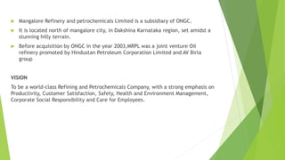
- MRPL is a subsidiary of ONGC located in Mangalore, Karnataka.
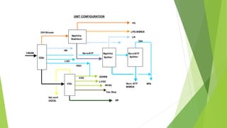
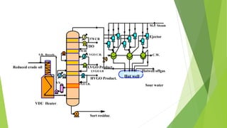
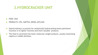
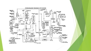
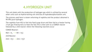
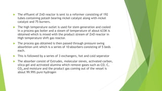
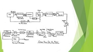
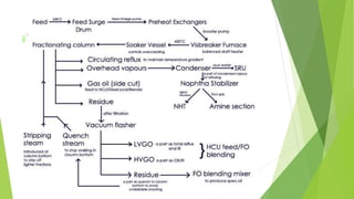
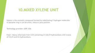
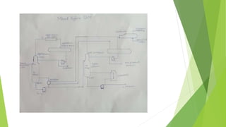
- The refinery's units include a crude distillation unit, vacuum distillation unit, hydrocracker unit, hydrogen unit, and gas oil hydrodesulfurization unit.
- Each unit is described briefly, outlining its key processes and products. The presentation aims to educate trainees on MRPL's refinery operations and configuration.