Downloaded 772 times
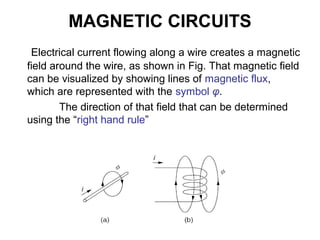
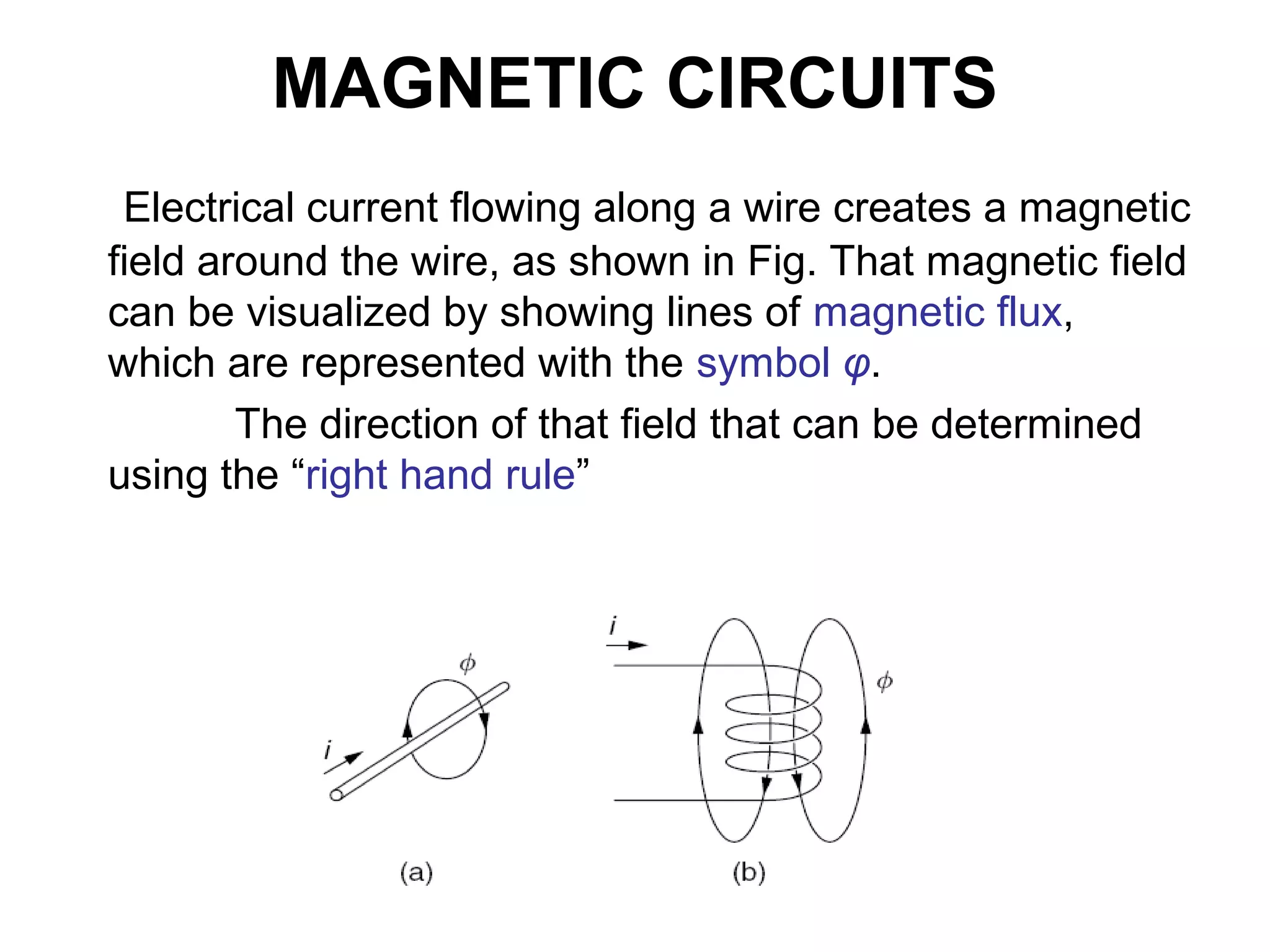
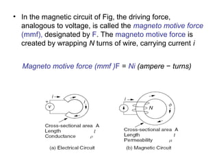
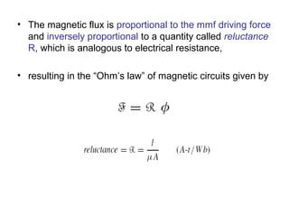
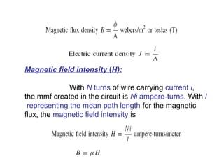
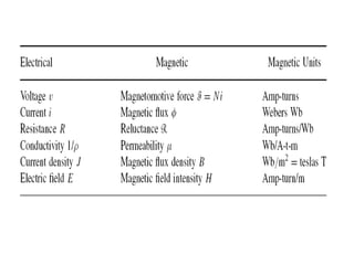
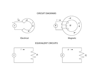
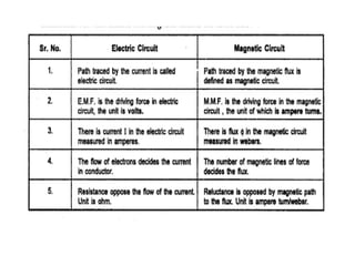
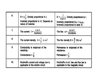
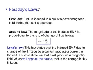
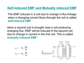
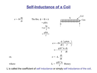
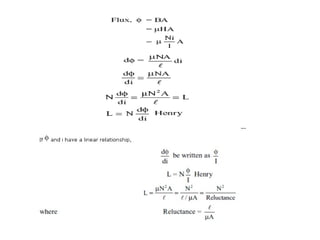

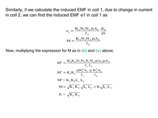
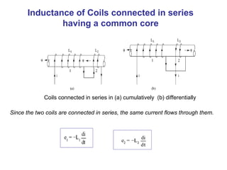
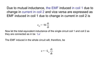
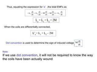
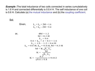

This document discusses magnetic circuits and electromagnetic induction. It defines key terms like magnetic flux, magnetomotive force, reluctance, self-inductance, and mutual inductance. Faraday's laws of induction state that an electromotive force (EMF) is induced in a coil when the magnetic flux through the coil changes. Lenz's law specifies that the induced EMF will oppose the change that created it. Magnetic circuits can be modeled similarly to electric circuits, with magnetomotive force, magnetic flux, and reluctance analogous to voltage, current, and resistance.


