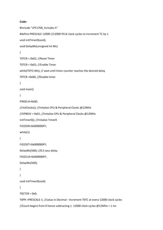
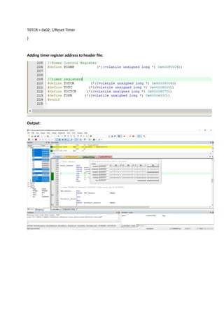
The document defines a function called DelayMs that uses Timer0 to create delays in milliseconds. It initializes Timer0 to increment every 12,000 clock cycles, which at a clock speed of 12MHz equals 1ms. The main function blinks an LED by turning it on for 500ms, then off for 500ms in a continuous loop using the DelayMs function.
this ppt only for beginner who want to understand concept of Timer counter operation of LPC2148 step by step.
hope it may help u.
always welcoming ur suggestion.
It has four 32-bit Timer blocks
Each Timer block can be used as a ‘Timer’ (like for e.g. triggering an interrupt every ‘t’ microseconds) or as a ‘Counter’ and can be also used to demodulate PWM signals given as input.
Each Timer module has its own Timer Counter(TC) and Prescale Register(PR) associated with it.
When a Timer is Reset and Enabled, the TC is set to 0 and incremented by 1 every ‘PR+1’ clock cycles
* What are Embedded Systems?
* C for Embedded Systems vs. Embedded C.
* Code Compilation process.
* Error types.
* Code Compilation using command line.
UART – Stands for Universal Asynchronous Receiver Transmitter It is a piece of hardware that acts as a bridge between the processor and the serial communication protocol or port (RS-232). It performs parallel – to – serial data conversion at the transmitter side and serial – to – parallel data conversion at the receiver side.Asynchronous serial communication.
A serial communication can be done using fewer wires as compared to its parallel counterpart. It is a cheapest communication device with a single wire for transmitting the data and another wire for receiving. When the high-speed data transfer is not required UART is used. In a simple serial communication, 3 pins are used: TxD, RxD and GND.
At Transmission side (i.e. From Microcontoller), one can write data into UART Data Register (e.g. UART0_DR) by using software code.
These 8 bits of data from Data Register is passed to Tx FIFO Buffer. After that, the data is sent out(one at a time) from Tx Shift Register.
TxFIFO flag = 1 (Buffer full) TxFIFO flag = 0 (not full - Software can write to Data Register)
At Receiver end, there is Rx FIFO Buffer.
RxFIFO Empty flag = 1 (Buffer is empty) RxFIFO Empty flag = 0 (Buffer has data to be read)
A frame is the unit of transmission in serial communications
Start bit: To declare the start of transmission.
Data bits: 4,5,6,7, or 8 bits of useful data bits.
Parity bit : To check for transmission errors.
Stop bit: To declare end of frame
Parity bit is used to check the integrity of a frame and signal if an error occurred during transmission.
It is an extra bit added to the end of a frame.
Even parity :The number of ‘1’ symbols inside a frame must always be even.
Odd parity : The number of ‘1’ symbols inside a frame must always be odd
The configuration settings at both ends of Txd and Rxd:
Full or half-duplex operation
Data length
Start/Stop bits
Transmission speed.
EX:-198 = 11000110
Transmission speed
Common speed = 9600 bits/sec
1/9600 = 104 us.
After detecting start it will count 104us and complets start bit.
Then begins sampling the input bits after 52us with equal count of 104us between each bit untill the next stop bit with high pulse.
Advantages
Requires minimum wires
No need for clock or any other timing signal.
Parity bit ensures basic error checking.
Disadvantages
Size of the data in the frame is limited.
Can connect only two devices at a time
Speed for data transfer is less compared to parallel.
Transmitter and receiver must agree to the rules of transmission and appropriate baud rate must be selected.
if we are looking for a device to device serial communication then UART proves itself the best as it is easy to deal with and also widely used in many peripheral devices.
This provides information related to ARM Cortex-M4 features , Modes, Registers etc. I have discussed importance of multiple stack pointers and privilege levels. STM32 Nucleo-L4R5ZI board is taken for this case study.
SE PAI Unit 5_Timer Programming in 8051 microcontroller_Part 2KanchanPatil34
2015 course SPPU SEIT syllabus of subject Processor Architecture and Interfacing (PAI) This covers Mode 1 and Mode 2 programming of timers, Counters and Counter Programming
Immunizing Image Classifiers Against Localized Adversary Attacksgerogepatton
This paper addresses the vulnerability of deep learning models, particularly convolutional neural networks
(CNN)s, to adversarial attacks and presents a proactive training technique designed to counter them. We
introduce a novel volumization algorithm, which transforms 2D images into 3D volumetric representations.
When combined with 3D convolution and deep curriculum learning optimization (CLO), itsignificantly improves
the immunity of models against localized universal attacks by up to 40%. We evaluate our proposed approach
using contemporary CNN architectures and the modified Canadian Institute for Advanced Research (CIFAR-10
and CIFAR-100) and ImageNet Large Scale Visual Recognition Challenge (ILSVRC12) datasets, showcasing
accuracy improvements over previous techniques. The results indicate that the combination of the volumetric
input and curriculum learning holds significant promise for mitigating adversarial attacks without necessitating
adversary training.
Industrial Training at Shahjalal Fertilizer Company Limited (SFCL)MdTanvirMahtab2
This presentation is about the working procedure of Shahjalal Fertilizer Company Limited (SFCL). A Govt. owned Company of Bangladesh Chemical Industries Corporation under Ministry of Industries.
Cosmetic shop management system project report.pdfKamal Acharya
Buying new cosmetic products is difficult. It can even be scary for those who have sensitive skin and are prone to skin trouble. The information needed to alleviate this problem is on the back of each product, but it's thought to interpret those ingredient lists unless you have a background in chemistry.
Instead of buying and hoping for the best, we can use data science to help us predict which products may be good fits for us. It includes various function programs to do the above mentioned tasks.
Data file handling has been effectively used in the program.
The automated cosmetic shop management system should deal with the automation of general workflow and administration process of the shop. The main processes of the system focus on customer's request where the system is able to search the most appropriate products and deliver it to the customers. It should help the employees to quickly identify the list of cosmetic product that have reached the minimum quantity and also keep a track of expired date for each cosmetic product. It should help the employees to find the rack number in which the product is placed.It is also Faster and more efficient way.
Saudi Arabia stands as a titan in the global energy landscape, renowned for its abundant oil and gas resources. It's the largest exporter of petroleum and holds some of the world's most significant reserves. Let's delve into the top 10 oil and gas projects shaping Saudi Arabia's energy future in 2024.
Sachpazis:Terzaghi Bearing Capacity Estimation in simple terms with Calculati...Dr.Costas Sachpazis
Terzaghi's soil bearing capacity theory, developed by Karl Terzaghi, is a fundamental principle in geotechnical engineering used to determine the bearing capacity of shallow foundations. This theory provides a method to calculate the ultimate bearing capacity of soil, which is the maximum load per unit area that the soil can support without undergoing shear failure. The Calculation HTML Code included.