Downloaded 167 times


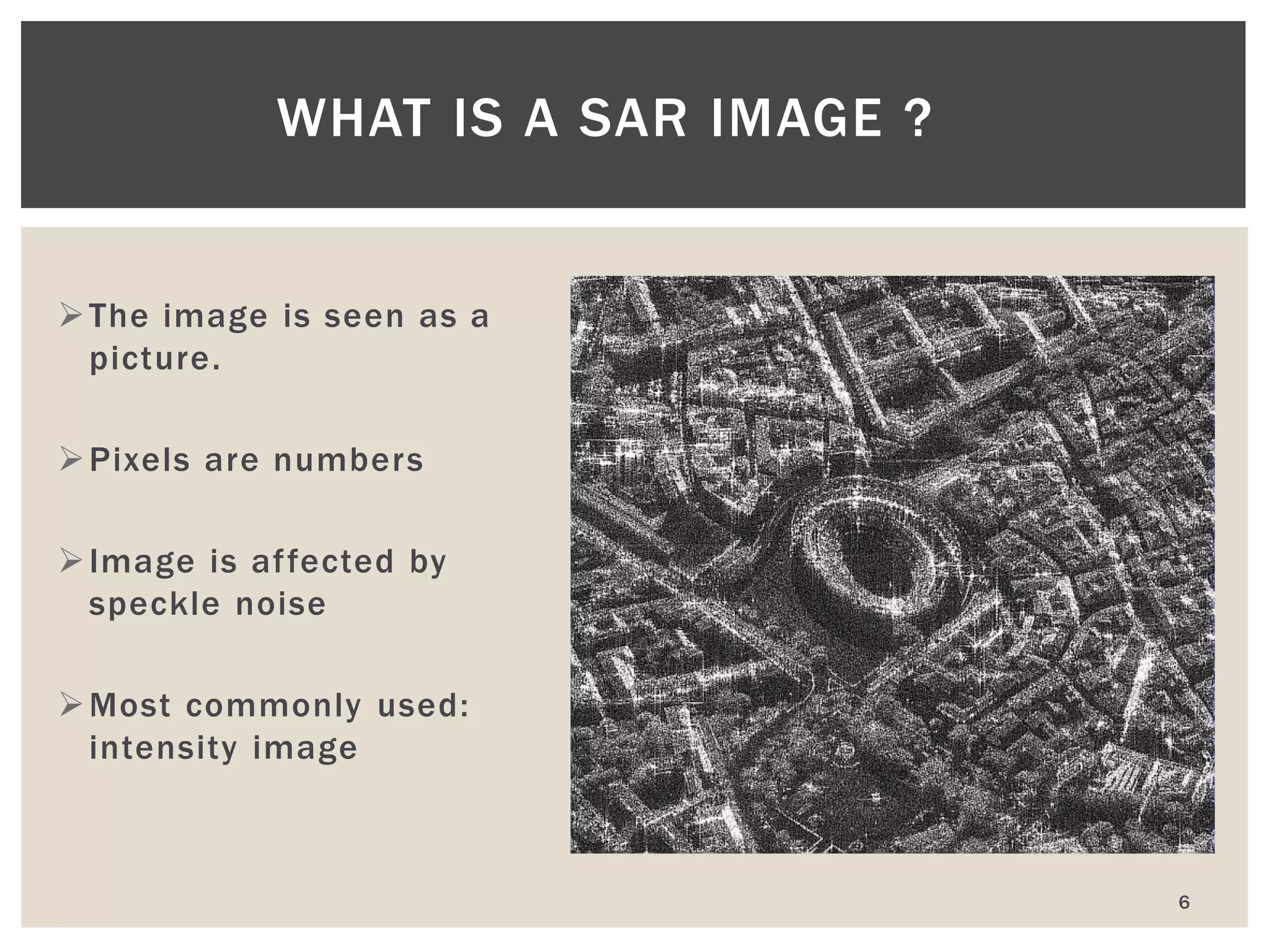


The document discusses advanced modes and features of Synthetic Aperture Radar (SAR) imaging, including radiometry, interferometry, and polarimetry, while detailing image characteristics such as geometry, speckle noise, and electrical properties. It covers the different types of SAR images, primarily focusing on intensity images, noise reduction techniques, and the impact of target properties on radar signatures. Additionally, it explores the effects of surface roughness, moisture content, and their interaction with radar energy, emphasizing the complexities of interpreting SAR images in various contexts.


