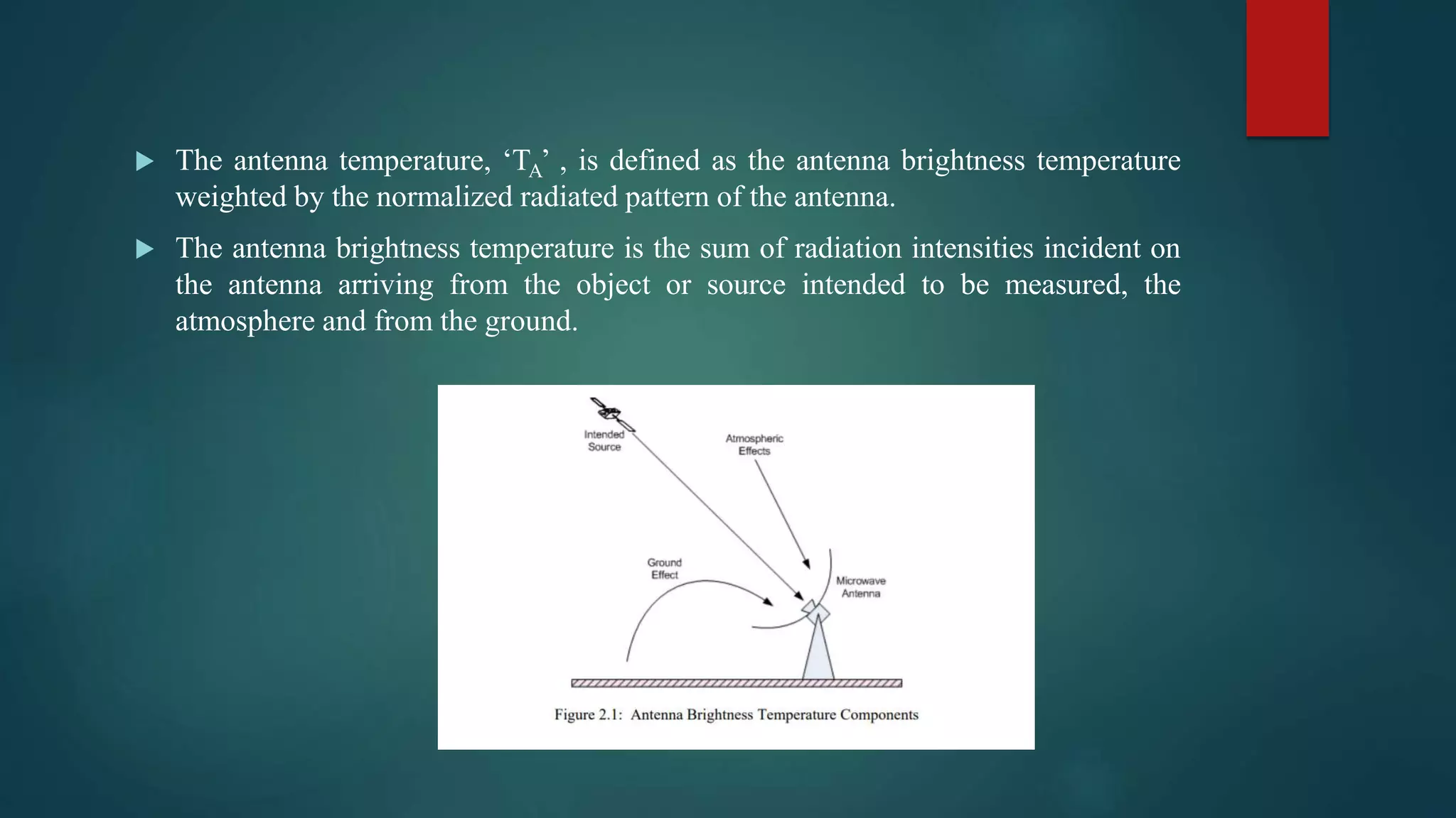
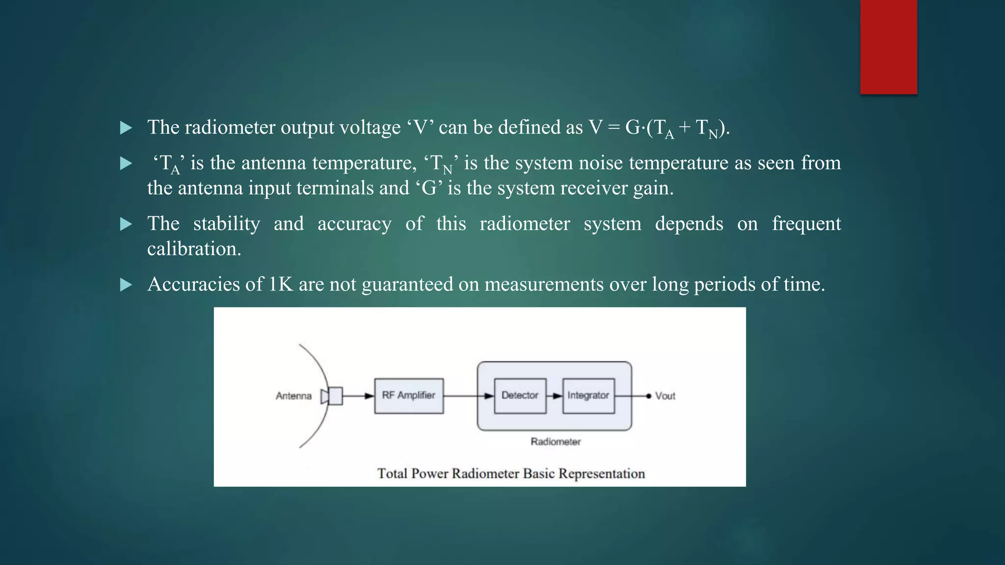
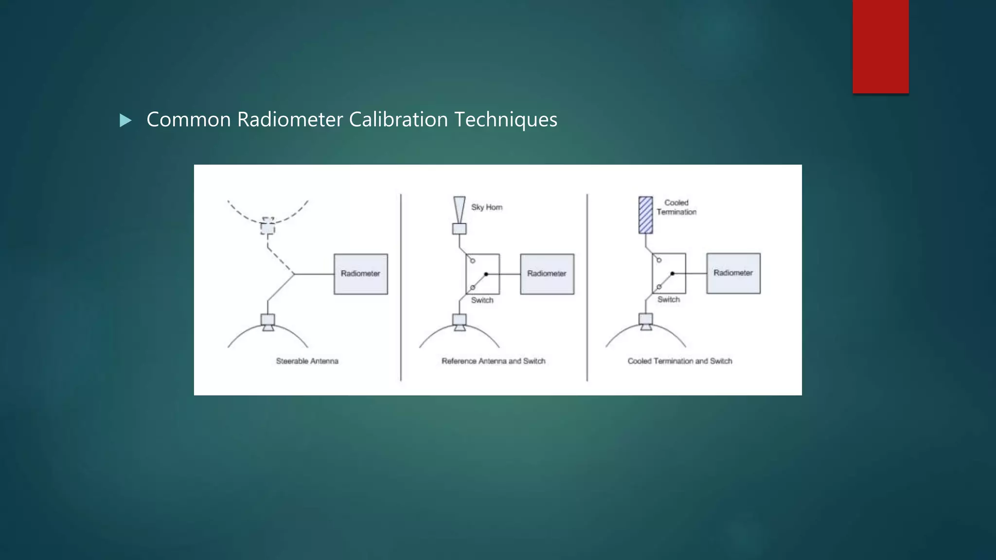
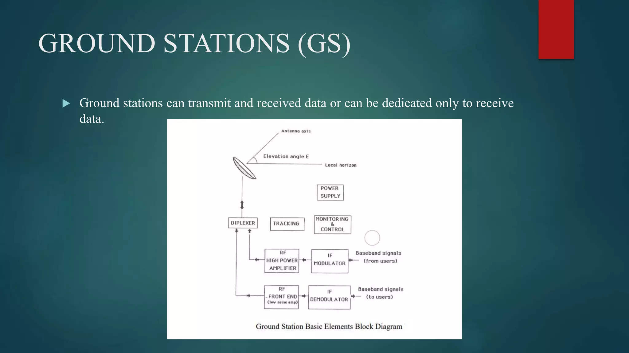
RADIOMETER AND BASICS OF
SATELLITE
COMMUNICATION SYSTEMS
PREPARED BY:- SHIVANGI SINGH
MICROWAVE ENGINEERING (2171001)
E.C DEPT.
RADIOMETER FUNDAMENTALS
 A radiometer is an instrument utilized to measure power.
 In some applications the power can be expressed as an equivalent temperature; the
temperature of a blackbody that would radiate the same amount of power. This
temperature is known as the brightness temperature.
 A basic radiometer system consists of at least of an antenna and a 6 receiver
containing a power detector.
 The electromagnetic (EM) emissions from the object intended to be measured are
sensed by the antenna; the amount of power transmitted to the receiver is
determined by the relationship P = k⋅TA⋅B where ‘P’ is the power per unit
bandwidth, ‘k’ is Boltzmann’s constant, ‘B’ is the radiometer receiver bandwidth,
and ‘TA’ is the antenna temperature.
 The antenna temperature, ‘TA’ , is defined as the antenna brightness temperature
weighted by the normalized radiated pattern of the antenna.
 The antenna brightness temperature is the sum of radiation intensities incident on
the antenna arriving from the object or source intended to be measured, the
atmosphere and from the ground.
TYPES OF RADIOMETER
There are various types of radiometers:
 Total Power Radiometer
 Dicke Signal-Modulated Radiometer
 Noise-Injection Signal-Modulated Radiometers are the most basic types.
 The simplest type is the Total Power Radiometer; all others are improved
variations of this basic radiometer system.
THE TOTAL POWER RADIOMETER
 The total power radiometer, also known as the absolute power radiometer, is in
essence composed of an antenna, an RF amplifier and a radiometer receiver
containing a detector and an integrator.
 Generally speaking the energy converging upon the antenna is amplified and
directed to the radiometer receiver where the signal is power detected by a noise
diode and dc-smoothed and post amplified utilizing an integrator.
 No electrical or mechanically modulation is present in this basic approach.
 The radiometer output voltage ‘V’ can be defined as V = G⋅(TA + TN).
 ‘TA’ is the antenna temperature, ‘TN’ is the system noise temperature as seen from
the antenna input terminals and ‘G’ is the system receiver gain.
 The stability and accuracy of this radiometer system depends on frequent
calibration.
 Accuracies of 1K are not guaranteed on measurements over long periods of time.
RADIOMETER CALIBRATION
 Different calibration techniques are utilized to keep the accuracy and stability of
radiometer systems.
 Three common methods of calibration are
 the “Steerable Antenna”,
 the “Reference Antenna and Switch”
 the “Cooled Termination and Switch”
The purpose of the radiometer calibration in addition to maintaining its stability and
accuracy is to obtain the radiometer transfer function that will reign for each
measurement session.
 Common Radiometer Calibration Techniques
RADIOMETER ANTENNA
 An important element in a radiometer system is the antenna, the piece of hardware
that collects the EM emissions for measurements.
 Antennas for communications and for radiometry purposes look alike but the
design constrains are different.
 Key factors to consider when designing an antenna for radiometry applications
are beam efficiency, antenna losses and antenna physical temperature; other
important constrains are directional gain, low sidelobes level, mismatching and
polarization.
SATELLITE COMMUNICATION
SYSTEM
A satellite communication system can be divided in three basic elements or so called
‘segments’.
 The ‘space segment’ consists of the satellite or satellites arranged in a certain way
that meets the user(s) needs.
 The ‘control segment’ manages the satellite resources and controls the spacecraft
though ground facilities.
 The ‘ground segment’ consisting of all the end users ground stations (GS).
 The end users GS size can range from small mobile units to large buildings
depending on the users needs and the communication technology employed.
 In some cases these stations are interconnected in a terrestrial network but can also
be individual entities.
SPACE SEGMENT SUBSYSTEMS
The subsystems present in space segment are called as space segment subsystems.
Following are the space segment subsystems.
 AOC Subsystem
 TTCM Subsystem
 Power and Antenna Subsystems
 Transponders
EARTH SEGMENT SUBSYSTEMS
 The subsystems present in the ground segment have the ability to access the
satellite repeater in order to provide the communication between the users.
 Earth segment is also called as ground segment.
 Earth segment performs mainly two functions. Those are transmission of a signal
to the satellite and reception of signal from the satellite.
 Earth stations are the major subsystems that are present in earth segment.
GROUND STATIONS (GS)
 Ground stations can transmit and received data or can be dedicated only to receive
data.
SATELLITE FREQUENCY BANDS
 The three most commonly used satellite frequency bands are the C band, Kuband,
and Ka-band. C-band and Ku-band are the two most common frequency
spectrums used by today's satellites
SATELLITE ORBITS
 A satellite, once in space follows a predetermined orbit, a complete revolution of
the spacecraft around the earth.
 Orbits come in various shapes and many factors are taken into account when
determining a communication satellite orbit such as the latitude of the surface to
be covered, the elevation angle, the duration of transmission (delay), the
interference, and the launch vehicle to be used among others.
 Common types of orbits are ‘Elliptical Orbits’, ‘Circular Low Earth Orbits
(LEO)’, ‘Circular Medium Earth Orbits (MEO)’, and ‘Circular Equatorial
Orbits’, ‘Geostationary Equatorial Orbit(GEO)’, ‘Polar Orbit’, ‘Sun-Synchronous
Orbit’.
THANK YOU

RADIOMETER AND BASICS OF SATELLITE COMMUNICATION SYSTEMS

  • 1.
    RADIOMETER AND BASICSOF SATELLITE COMMUNICATION SYSTEMS PREPARED BY:- SHIVANGI SINGH MICROWAVE ENGINEERING (2171001) E.C DEPT.
  • 2.
    RADIOMETER FUNDAMENTALS  Aradiometer is an instrument utilized to measure power.  In some applications the power can be expressed as an equivalent temperature; the temperature of a blackbody that would radiate the same amount of power. This temperature is known as the brightness temperature.  A basic radiometer system consists of at least of an antenna and a 6 receiver containing a power detector.  The electromagnetic (EM) emissions from the object intended to be measured are sensed by the antenna; the amount of power transmitted to the receiver is determined by the relationship P = k⋅TA⋅B where ‘P’ is the power per unit bandwidth, ‘k’ is Boltzmann’s constant, ‘B’ is the radiometer receiver bandwidth, and ‘TA’ is the antenna temperature.
  • 3.
     The antennatemperature, ‘TA’ , is defined as the antenna brightness temperature weighted by the normalized radiated pattern of the antenna.  The antenna brightness temperature is the sum of radiation intensities incident on the antenna arriving from the object or source intended to be measured, the atmosphere and from the ground.
  • 4.
    TYPES OF RADIOMETER Thereare various types of radiometers:  Total Power Radiometer  Dicke Signal-Modulated Radiometer  Noise-Injection Signal-Modulated Radiometers are the most basic types.  The simplest type is the Total Power Radiometer; all others are improved variations of this basic radiometer system.
  • 5.
    THE TOTAL POWERRADIOMETER  The total power radiometer, also known as the absolute power radiometer, is in essence composed of an antenna, an RF amplifier and a radiometer receiver containing a detector and an integrator.  Generally speaking the energy converging upon the antenna is amplified and directed to the radiometer receiver where the signal is power detected by a noise diode and dc-smoothed and post amplified utilizing an integrator.  No electrical or mechanically modulation is present in this basic approach.
  • 6.
     The radiometeroutput voltage ‘V’ can be defined as V = G⋅(TA + TN).  ‘TA’ is the antenna temperature, ‘TN’ is the system noise temperature as seen from the antenna input terminals and ‘G’ is the system receiver gain.  The stability and accuracy of this radiometer system depends on frequent calibration.  Accuracies of 1K are not guaranteed on measurements over long periods of time.
  • 7.
    RADIOMETER CALIBRATION  Differentcalibration techniques are utilized to keep the accuracy and stability of radiometer systems.  Three common methods of calibration are  the “Steerable Antenna”,  the “Reference Antenna and Switch”  the “Cooled Termination and Switch” The purpose of the radiometer calibration in addition to maintaining its stability and accuracy is to obtain the radiometer transfer function that will reign for each measurement session.
  • 8.
     Common RadiometerCalibration Techniques
  • 9.
    RADIOMETER ANTENNA  Animportant element in a radiometer system is the antenna, the piece of hardware that collects the EM emissions for measurements.  Antennas for communications and for radiometry purposes look alike but the design constrains are different.  Key factors to consider when designing an antenna for radiometry applications are beam efficiency, antenna losses and antenna physical temperature; other important constrains are directional gain, low sidelobes level, mismatching and polarization.
  • 10.
    SATELLITE COMMUNICATION SYSTEM A satellitecommunication system can be divided in three basic elements or so called ‘segments’.  The ‘space segment’ consists of the satellite or satellites arranged in a certain way that meets the user(s) needs.  The ‘control segment’ manages the satellite resources and controls the spacecraft though ground facilities.  The ‘ground segment’ consisting of all the end users ground stations (GS).  The end users GS size can range from small mobile units to large buildings depending on the users needs and the communication technology employed.  In some cases these stations are interconnected in a terrestrial network but can also be individual entities.
  • 11.
    SPACE SEGMENT SUBSYSTEMS Thesubsystems present in space segment are called as space segment subsystems. Following are the space segment subsystems.  AOC Subsystem  TTCM Subsystem  Power and Antenna Subsystems  Transponders
  • 12.
    EARTH SEGMENT SUBSYSTEMS The subsystems present in the ground segment have the ability to access the satellite repeater in order to provide the communication between the users.  Earth segment is also called as ground segment.  Earth segment performs mainly two functions. Those are transmission of a signal to the satellite and reception of signal from the satellite.  Earth stations are the major subsystems that are present in earth segment.
  • 13.
    GROUND STATIONS (GS) Ground stations can transmit and received data or can be dedicated only to receive data.
  • 14.
    SATELLITE FREQUENCY BANDS The three most commonly used satellite frequency bands are the C band, Kuband, and Ka-band. C-band and Ku-band are the two most common frequency spectrums used by today's satellites
  • 15.
    SATELLITE ORBITS  Asatellite, once in space follows a predetermined orbit, a complete revolution of the spacecraft around the earth.  Orbits come in various shapes and many factors are taken into account when determining a communication satellite orbit such as the latitude of the surface to be covered, the elevation angle, the duration of transmission (delay), the interference, and the launch vehicle to be used among others.  Common types of orbits are ‘Elliptical Orbits’, ‘Circular Low Earth Orbits (LEO)’, ‘Circular Medium Earth Orbits (MEO)’, and ‘Circular Equatorial Orbits’, ‘Geostationary Equatorial Orbit(GEO)’, ‘Polar Orbit’, ‘Sun-Synchronous Orbit’.
  • 16.