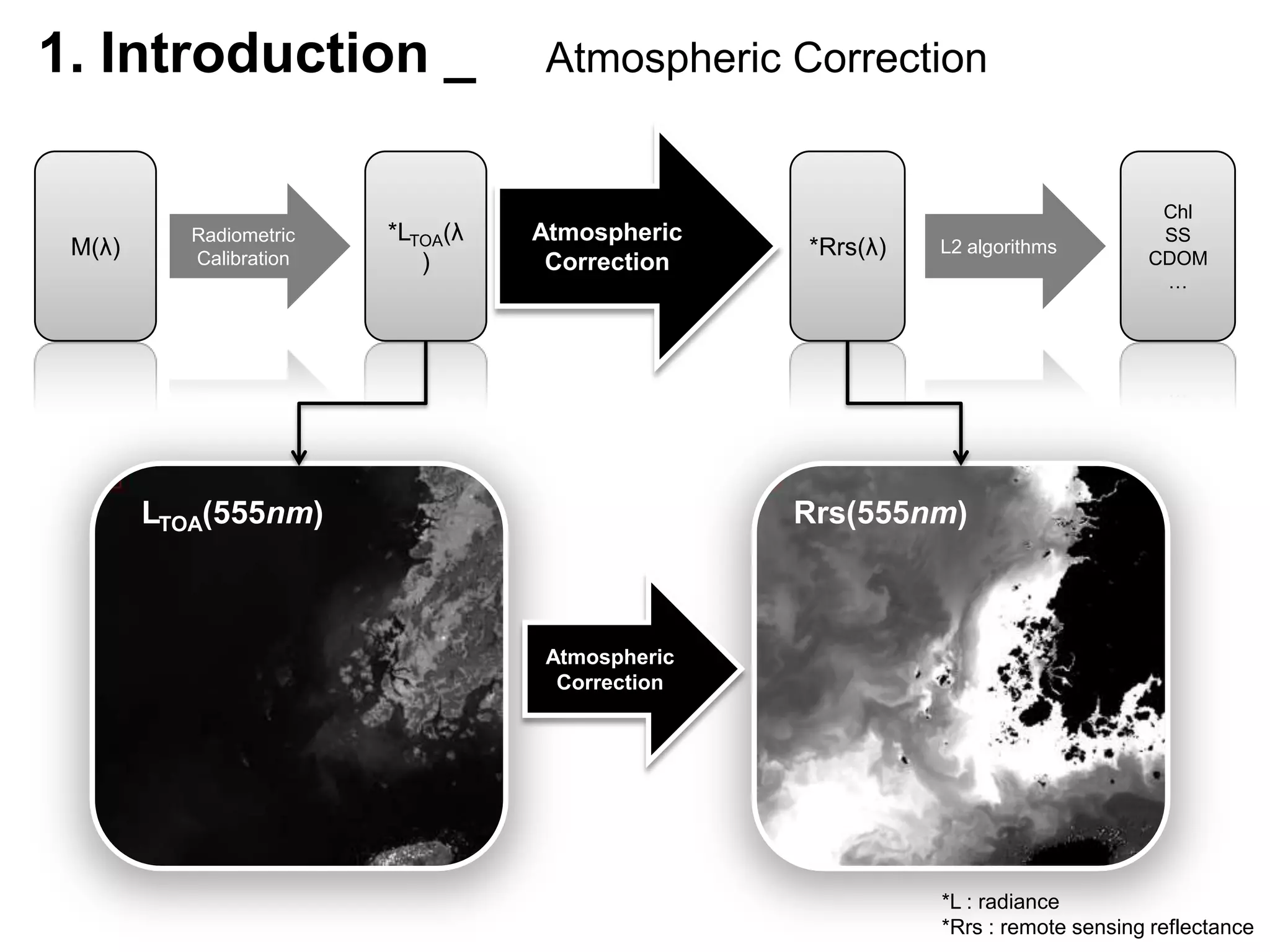
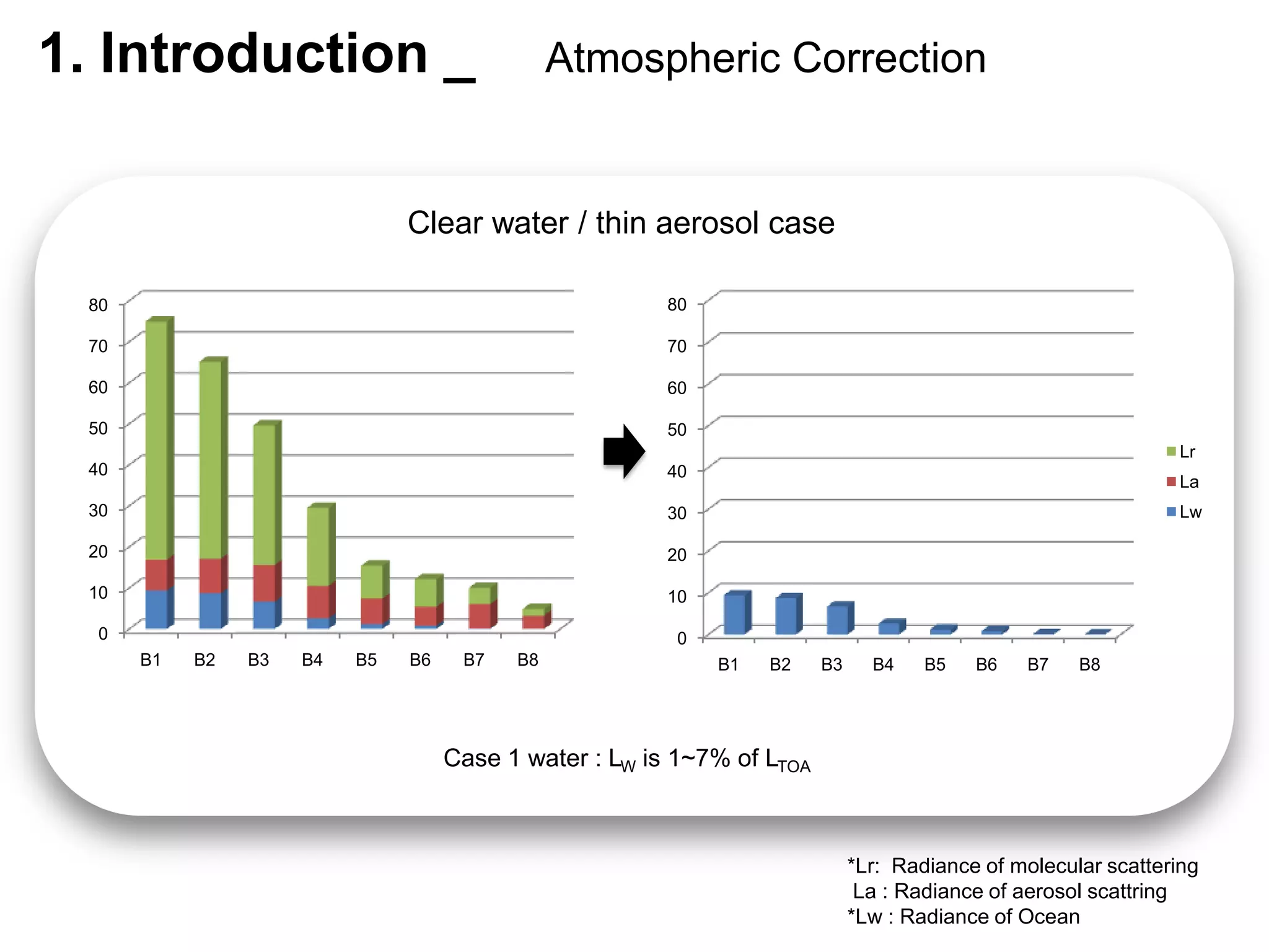
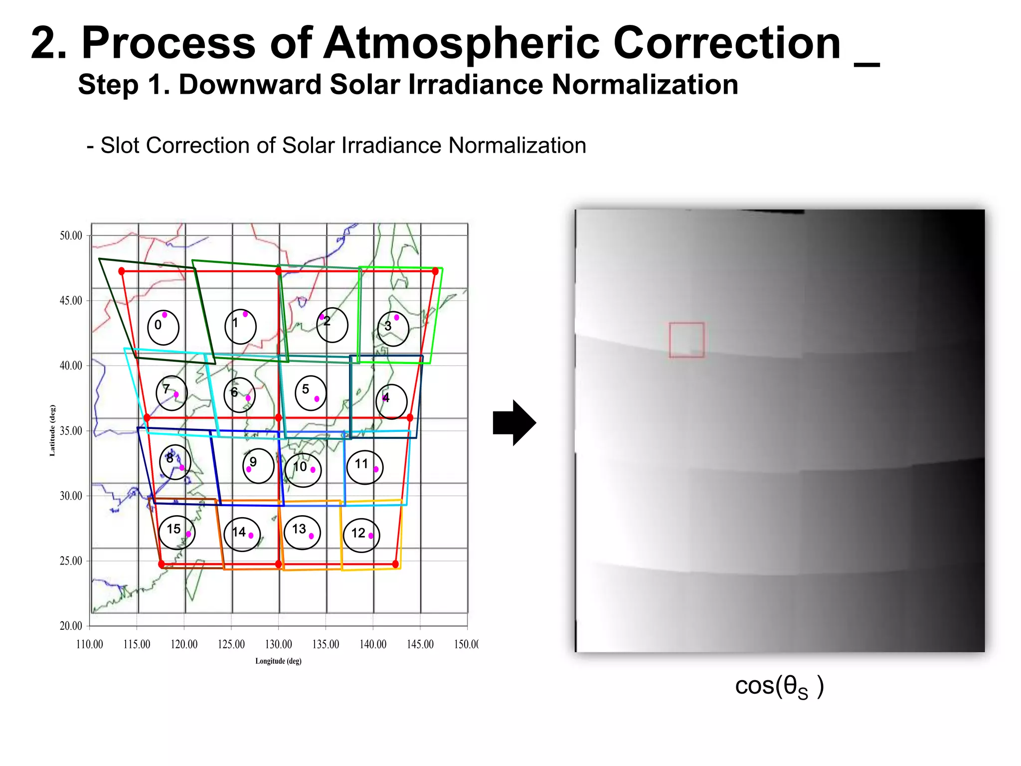
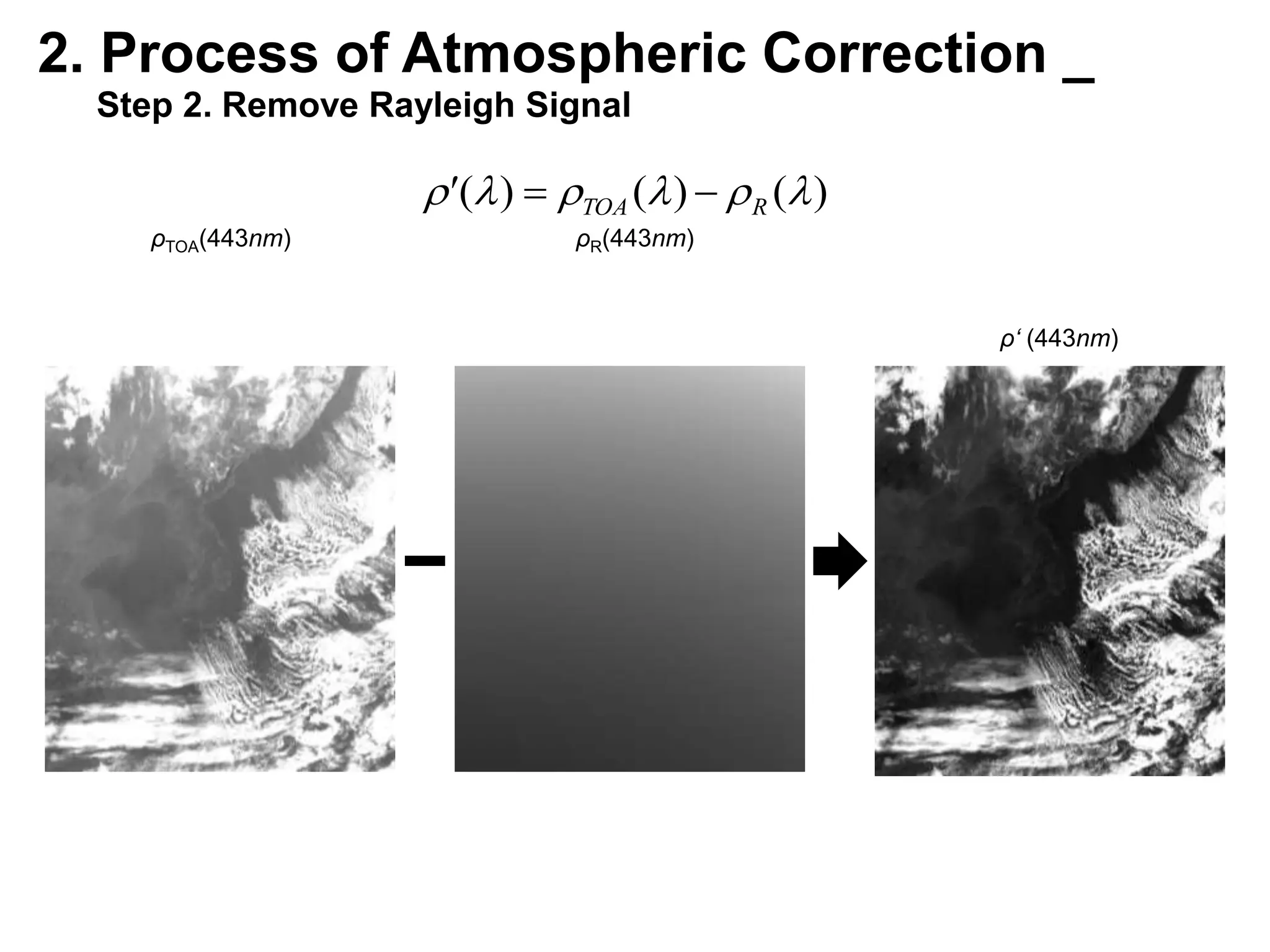
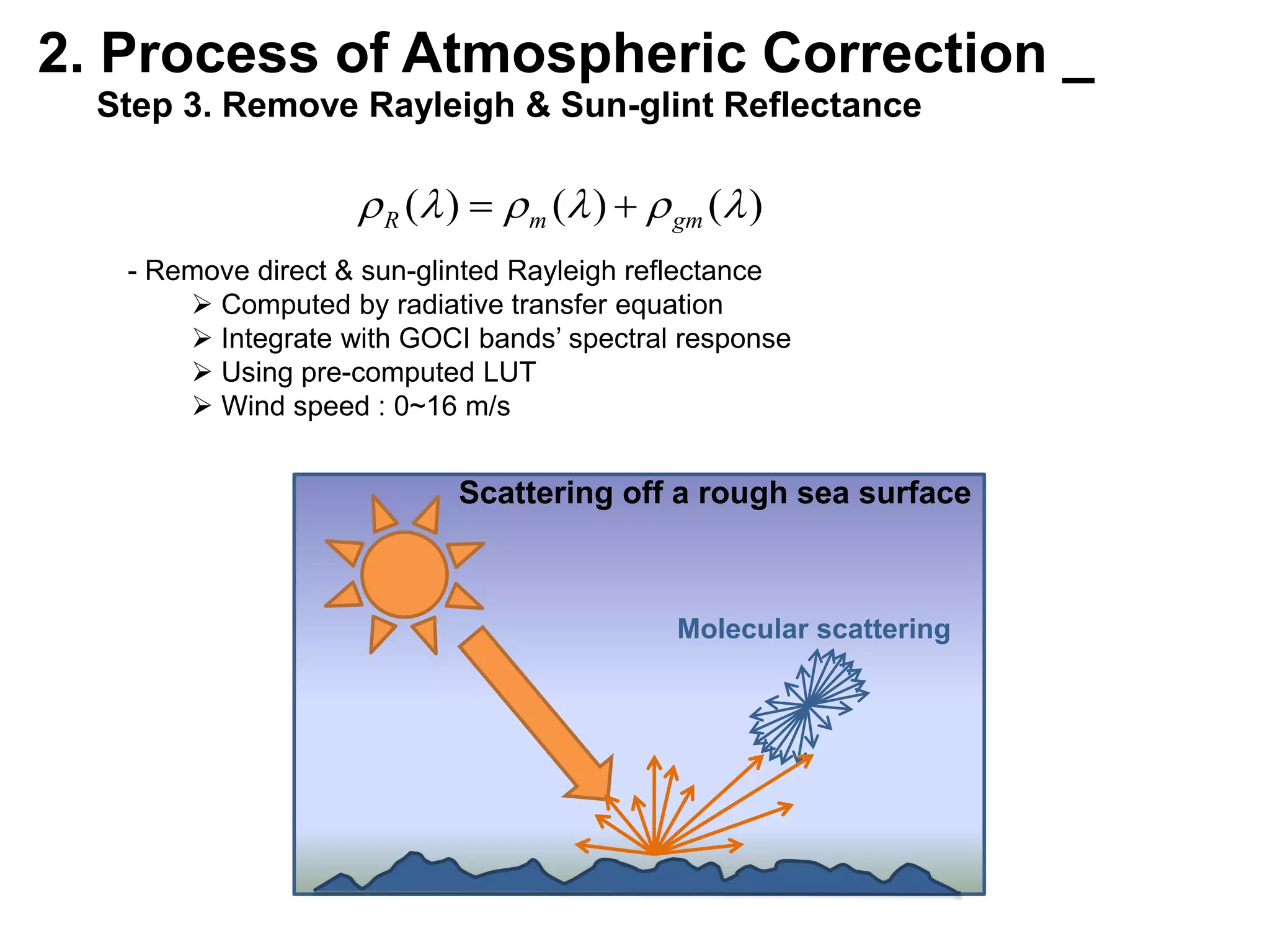
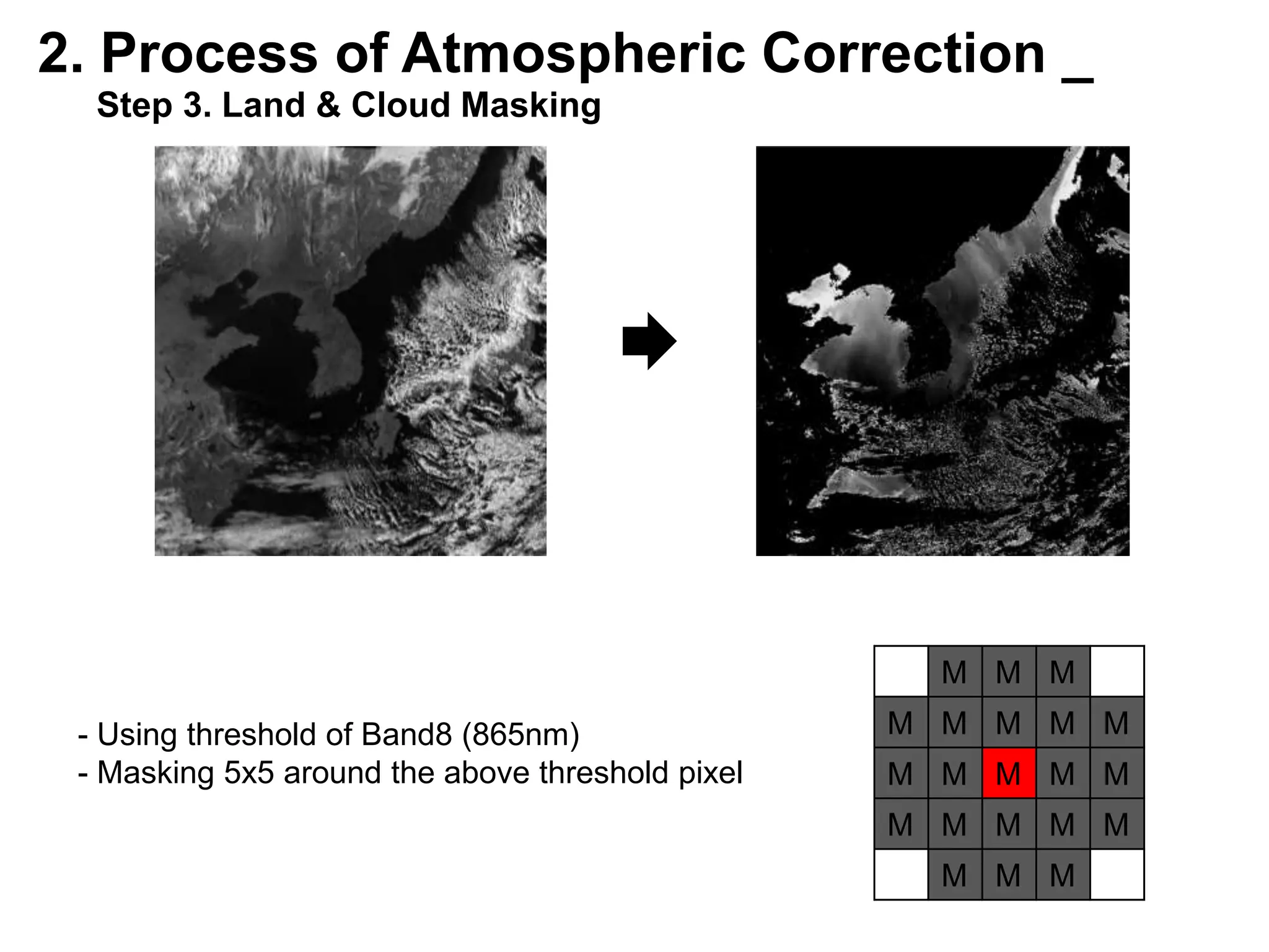
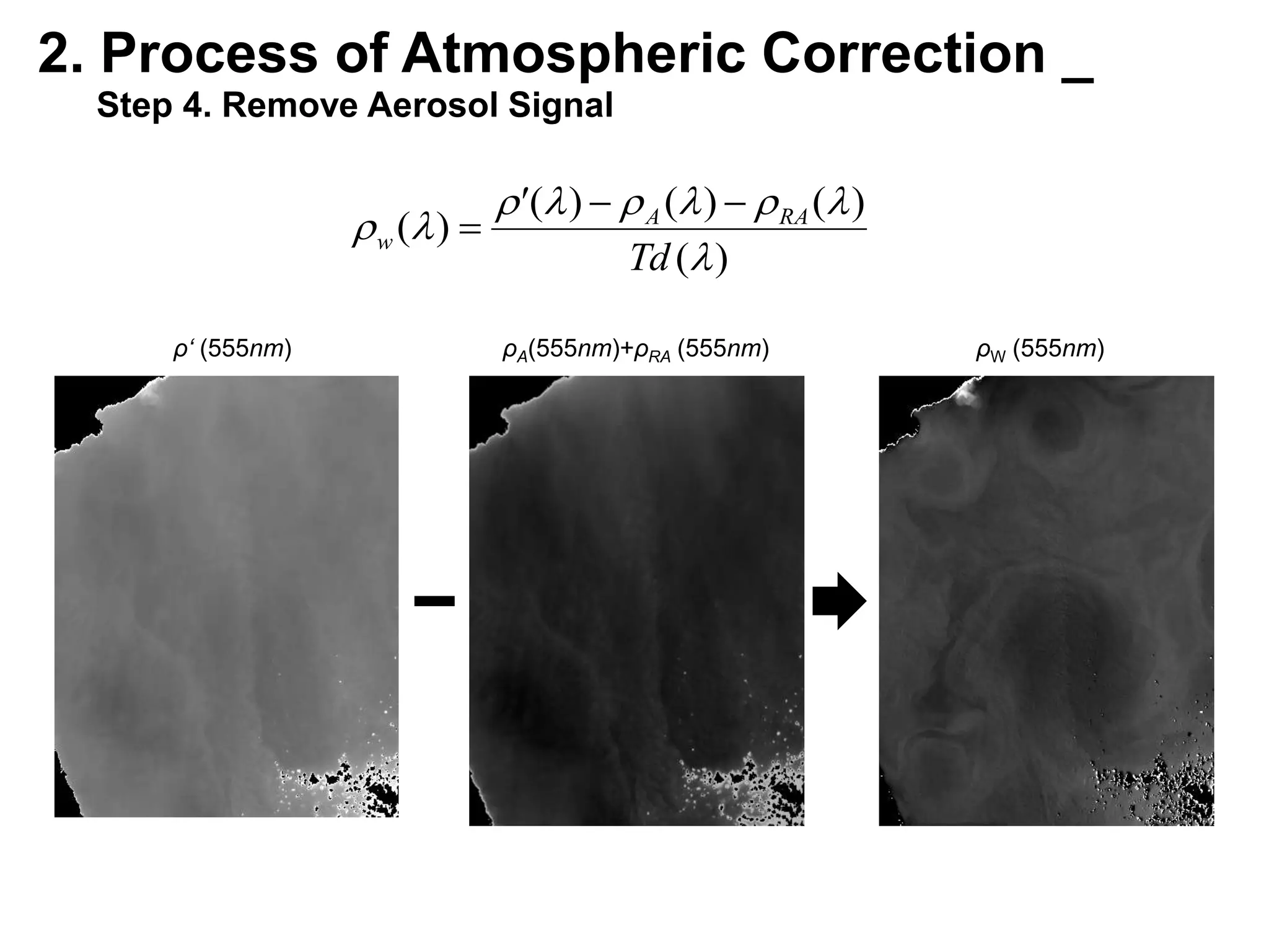
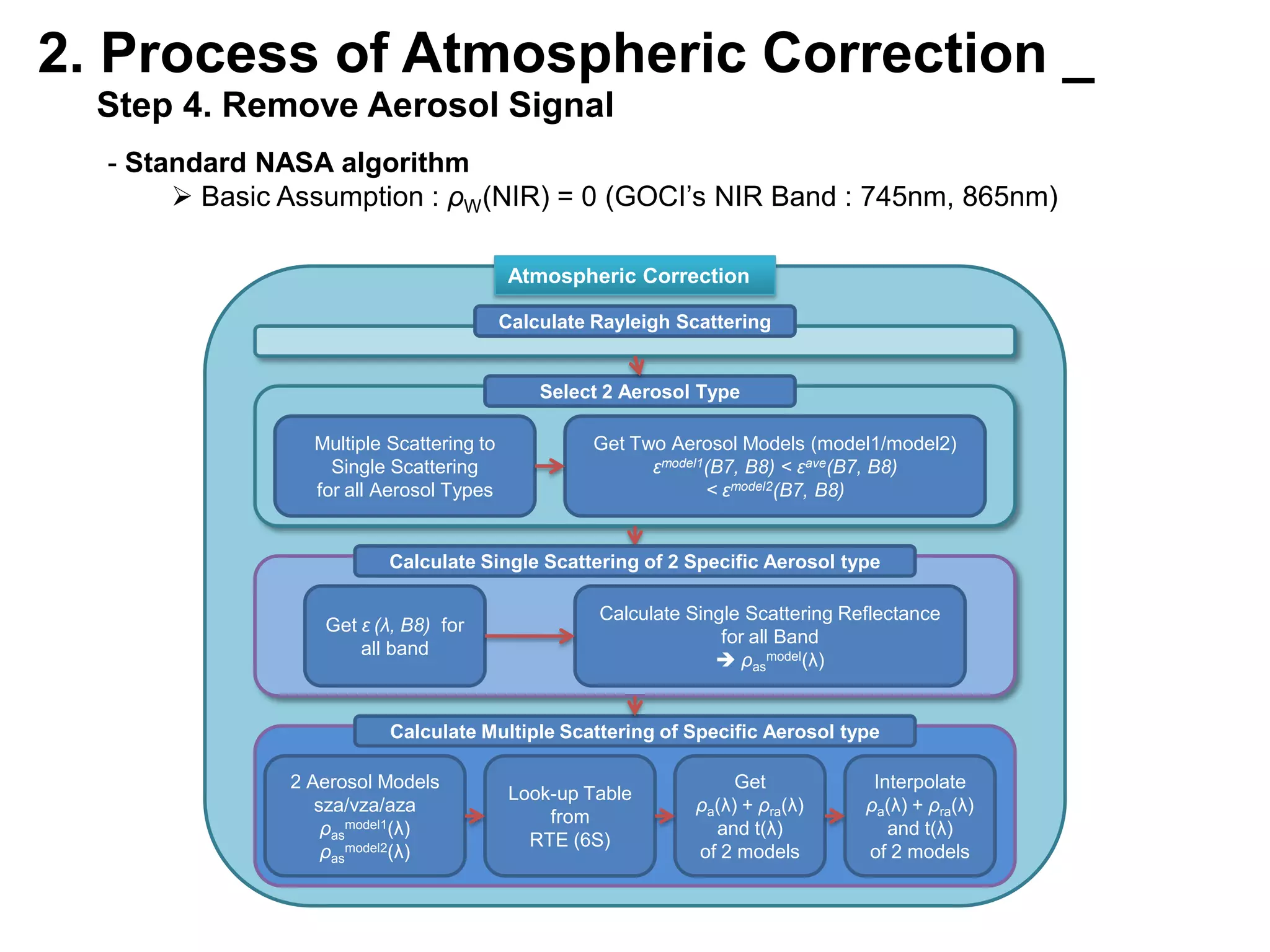
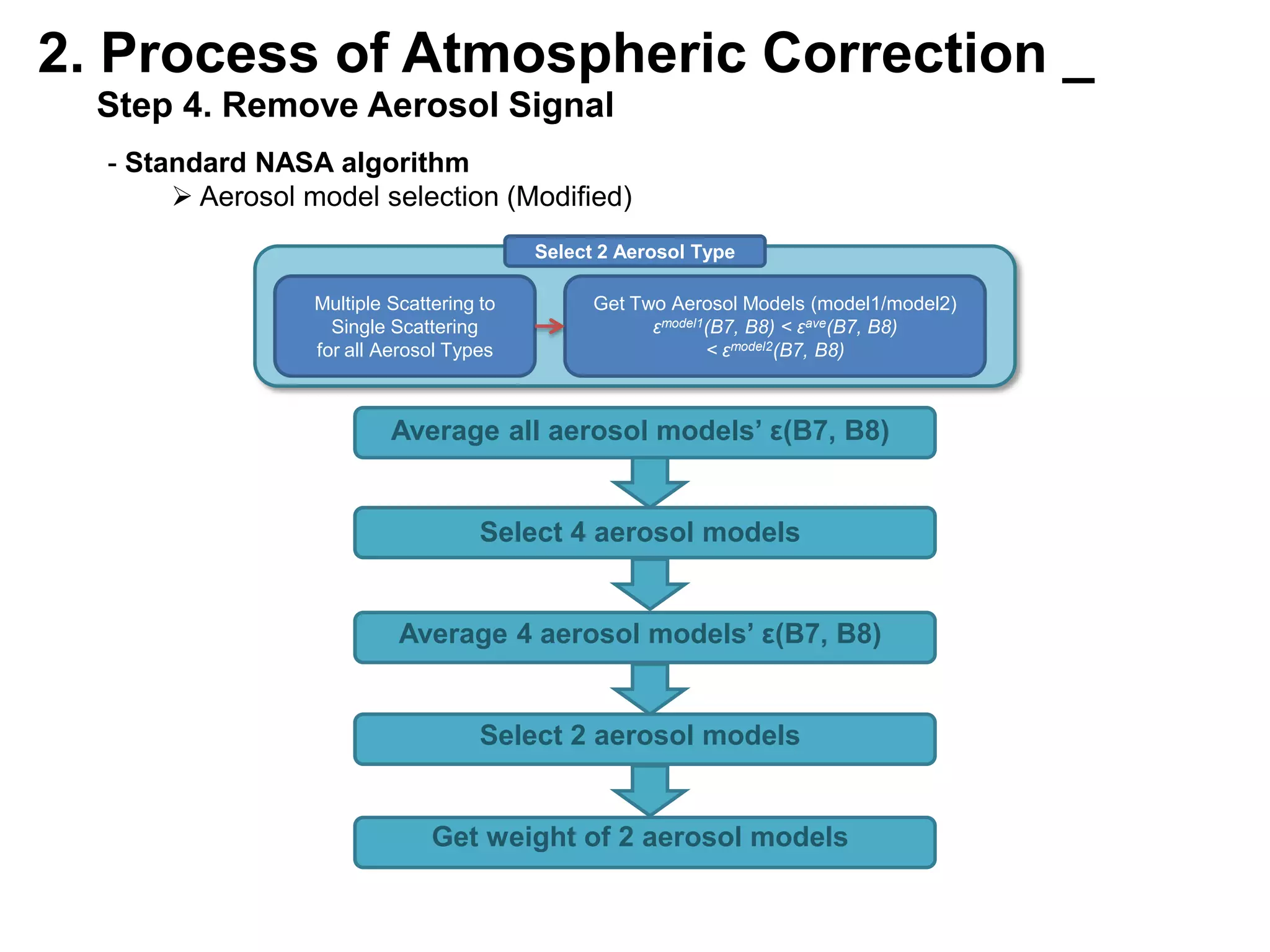
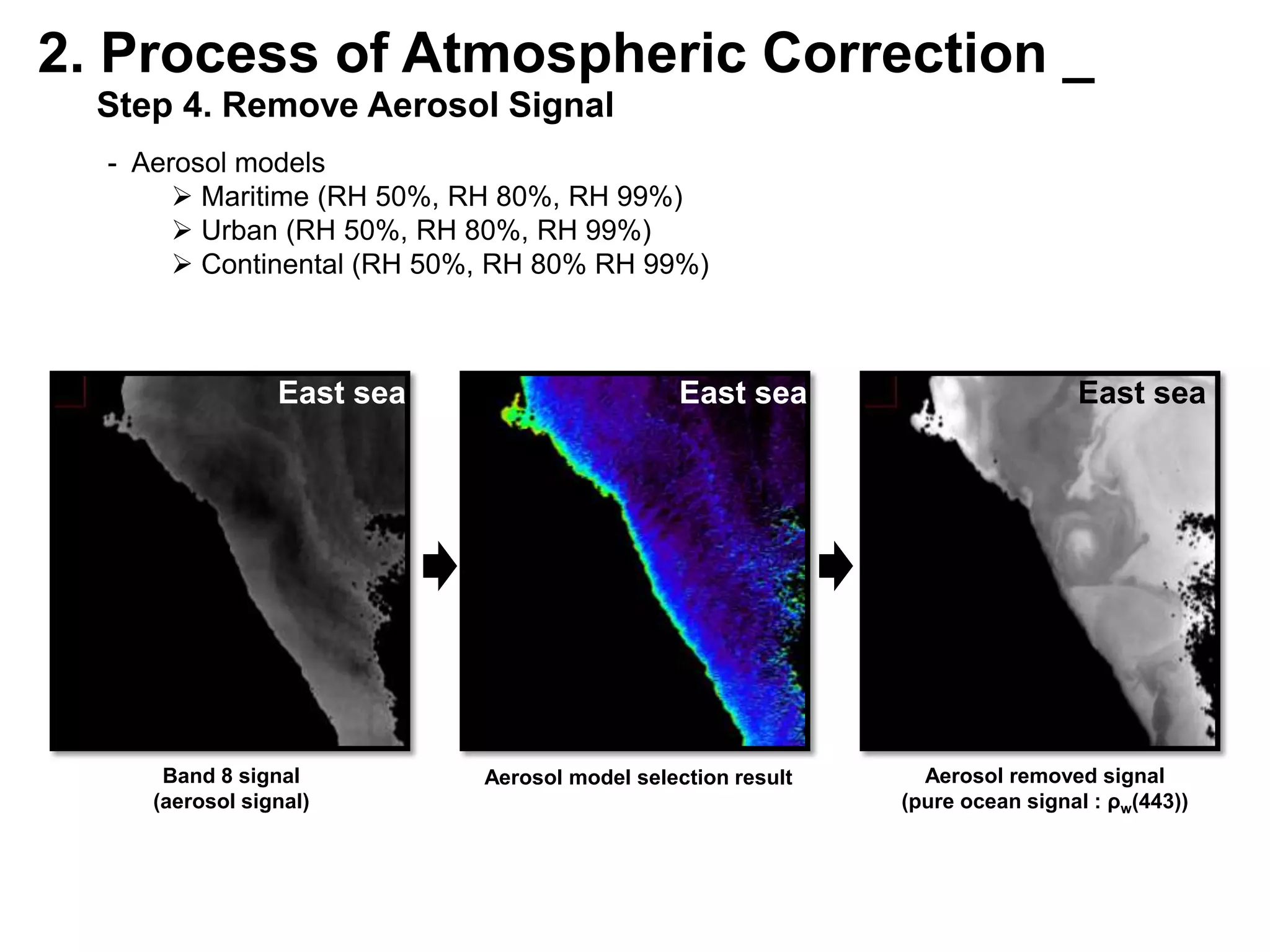
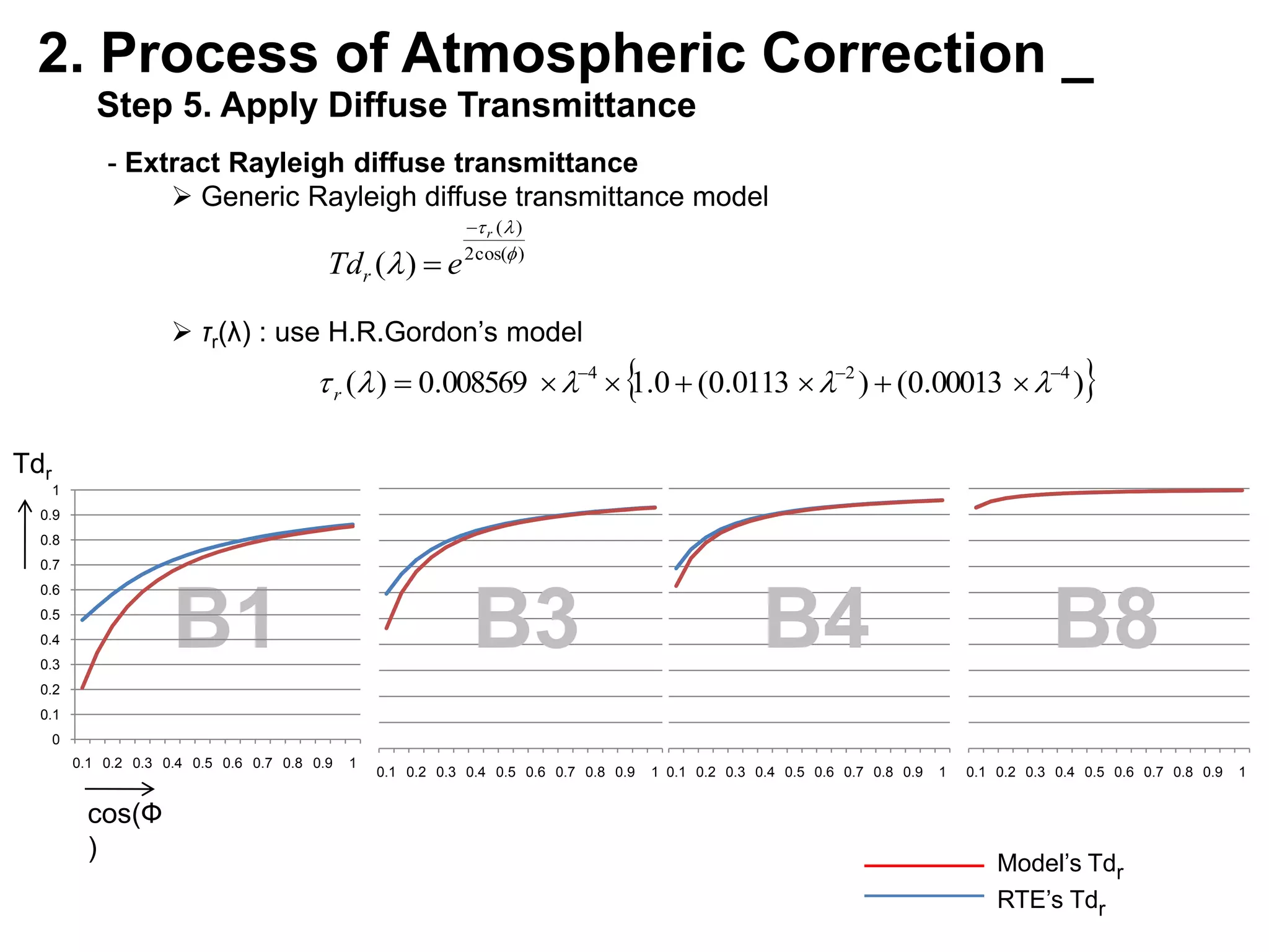
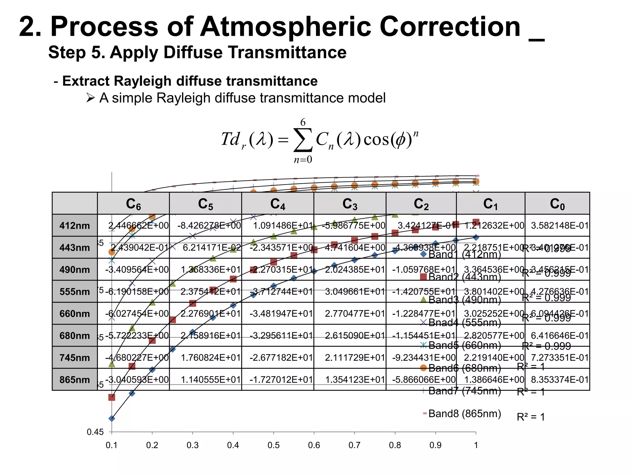
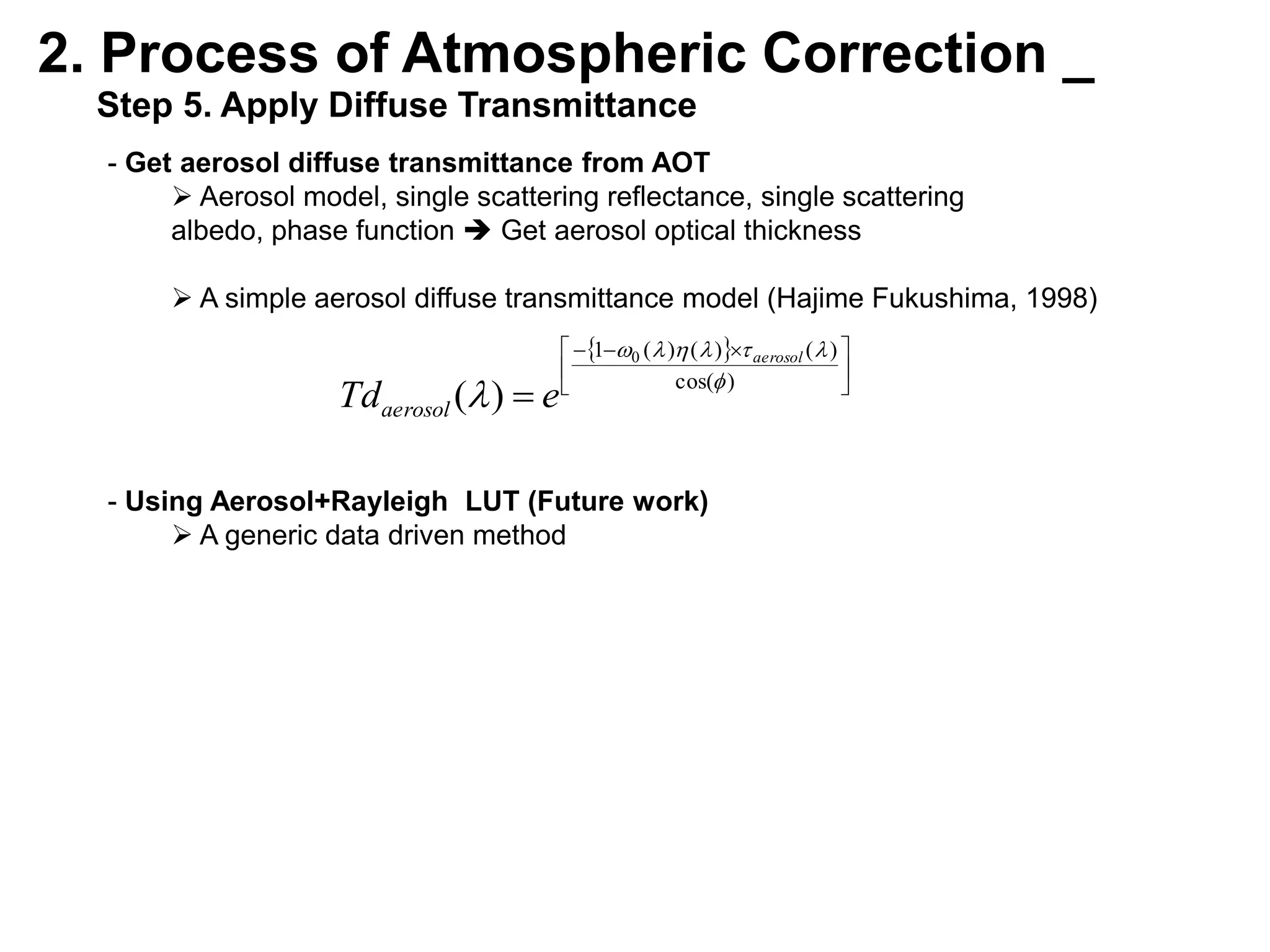
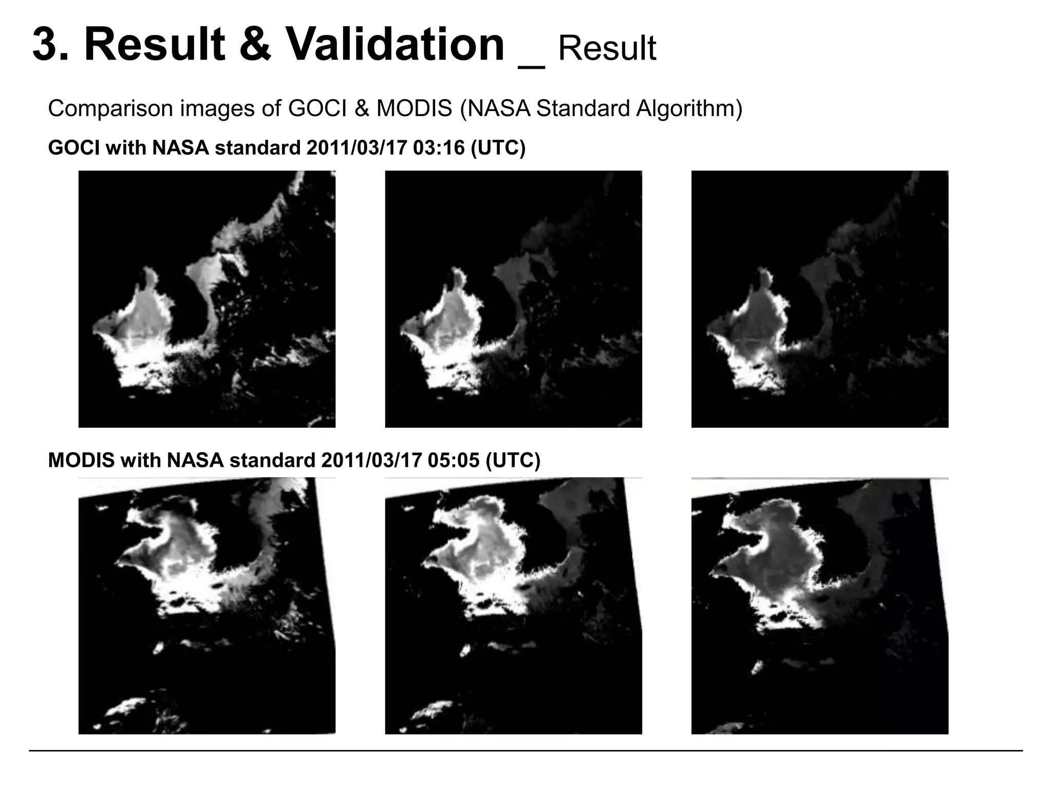
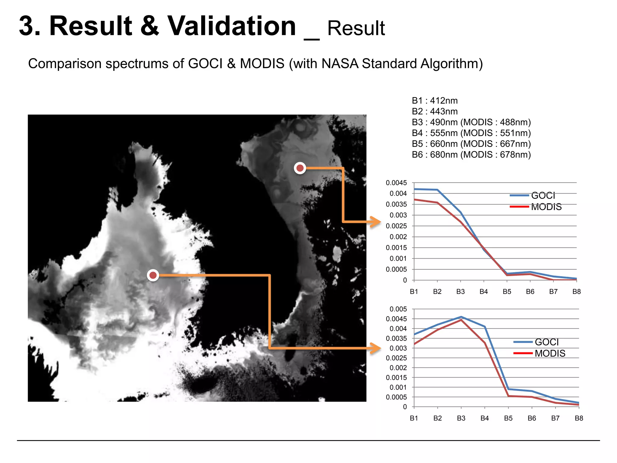
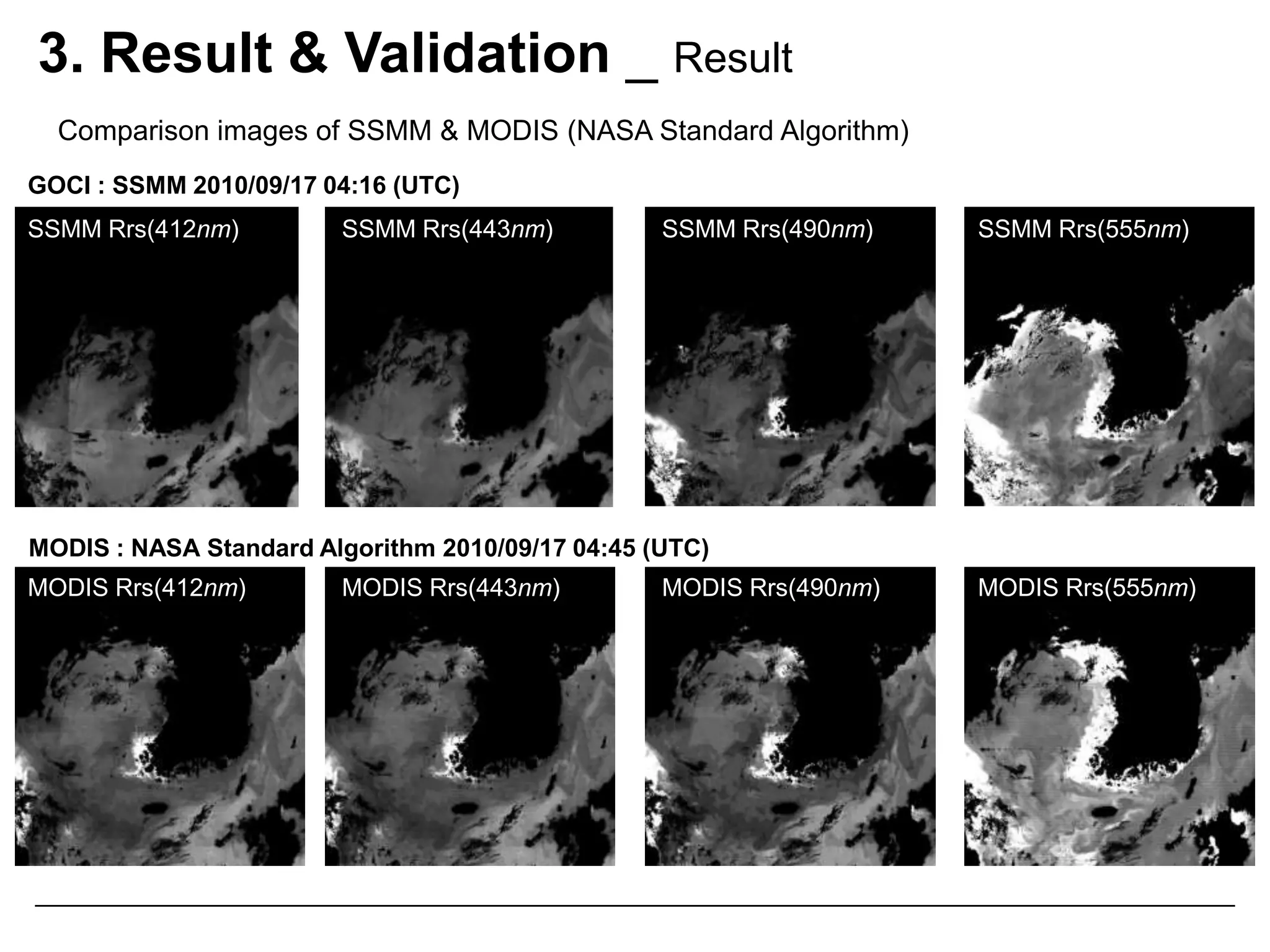
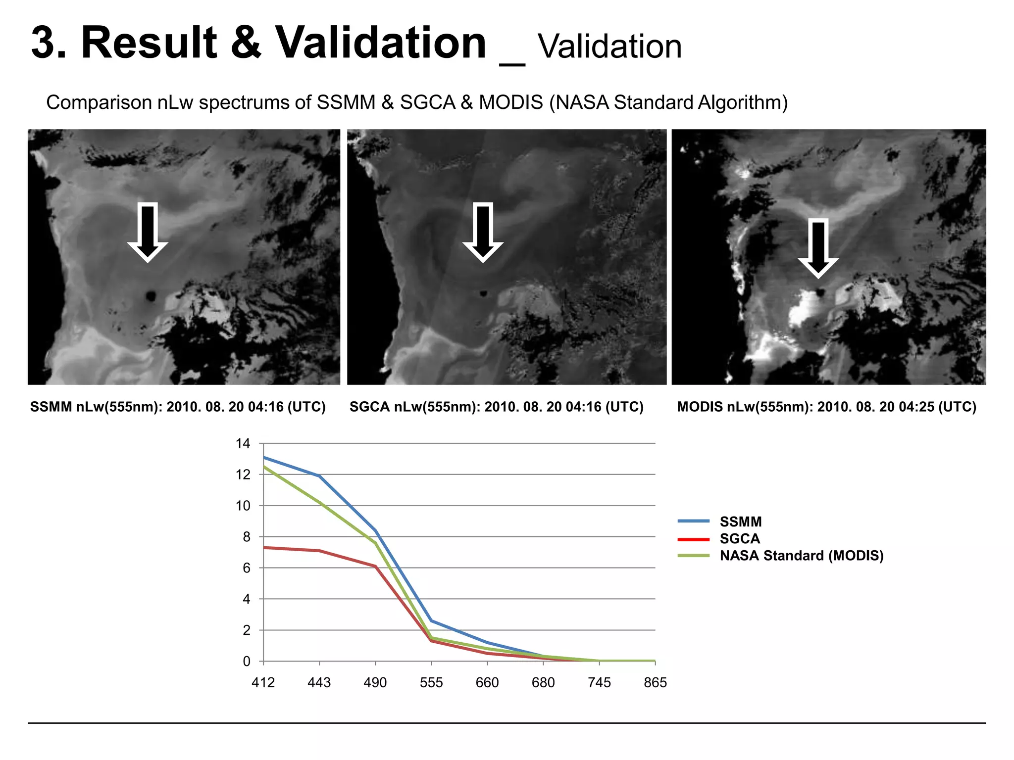
Atmospheric Correction Algorithmfor the GOCIJae Hyun Ahn*Joo-HyungRyu*Young Jae Park*Yu-Hwan Ahn*Im Sang Oh**Korea Ocean Research & Development InstituteSeoul National University
I n d e x  _Introduction _Atmospheric Correction
Atmospheric Algorithms of the GOCI> Standard NASA Algorithm> SGCA> SSMMProcess of Atmospheric Correction _Standard NASA Algorithm
SGCA
SSMMResult & Validation _Result
ValidationConclusion _Ocean Color
1. Introduction _	Atmospheric CorrectionAtmosphericCorrectionM(λ)*LTOA(λ)*Rrs(λ)ChlSSCDOM…Radiometric CalibrationL2 algorithmsLTOA(555nm)Rrs(555nm)AtmosphericCorrection*L : radiance*Rrs : remote sensing reflectance
1. Introduction _Atmospheric CorrectionClear water / thin aerosol caseCase 1 water : LWis 1~7% of LTOA*Lr:  Radiance of molecular scattering La : Radiance of aerosol scattring*Lw : Radiance of Ocean
1. Introduction _Atmospheric CorrectionIssue : GOCI has longer optical path than the polar orbit satelliteObservation areaEarthGOCIequator26˚ < Satellite zenith angle < 55˚(MODIS : 0˚ < Satellite zenith angle < 40˚)
Introduction _3atmospheric Algorithms of the GOCIStandard NASA algorithmA classical standard atmospheric correction algorithm
Developed by M.Wang & H.R.Gordon
Aerosol selection, turbid-water iterative method, diffuse transmittance models are updated by J.H.AhnSSMM (Spectral Shape Matching Method)Developed by Y.H.Ahn & P.Shanmugam
Using reference site
Aerosol models updated by J.H.AhnSGCA (Sun-Glint Correction Algorithm)Developed by HYGEOS
Removing sun-glint & atmospheric signal
Polynomial fitting algorithm (ocean color & atmospheric model)2. Process of Atmospheric Correction _Raw ImageRadiometric Calibration & Geometric CorrectionGeometric Corrected TOA Radiance ImageLTOA(λ)Downward Solar Irradiance Normalization Longitude, Latitude, Time, SZA, VZA, AZAReflectance of TOA Imageρ(λ)=ρ‘ (λ) + ρR (λ)Remove Rayleigh & Sun-glint Reflectance & Mask Radiative Transfer Equation,  Cox&Munk ModelReflectance of Ocean + Aerosol Imageρ‘ (λ) = Td(λ)ρW(λ) + ρA(λ) + ρRA(λ)Atmospheric CorrectionRemove Aerosol ReflectanceRadiative Transfer Equation,  Aerosol ModelReflectance of Ocean ImageρW(λ)StandardNASAAlgorithmSSMMSGCAReflectance of Ocean ImageRrs(λ)Underwater AlgorithmLevel 2 ProductChl, SS, CDOM, Kd490, …
2. Process of Atmospheric Correction _   Step 1. Downward Solar Irradiance NormalizationLTOA(λ)ρTOA (λ)Downward Solar IrradianceNormalizationcos(θS)*θS: solar zenith angle
F0(λ) : Extraterrestrial spectral irradiance21035764891110131514122. Process of Atmospheric Correction _   Step 1. Downward Solar Irradiance Normalization Slot Correction of Solar Irradiance Normalizationcos(θS)
2. Process of Atmospheric Correction _   Step 2. Remove Rayleigh SignalρTOA(443nm)ρR(443nm)ρ‘ (443nm)
2. Process of Atmospheric Correction _   Step 3. Remove Rayleigh & Sun-glint Reflectance Remove direct & sun-glinted Rayleigh reflectance
 Computed by radiative transfer equation
 Integrate with GOCI bands’ spectral response
 Using pre-computed LUT
 Wind speed : 0~16 m/sScattering off a rough sea surfaceMolecular scattering
2. Process of Atmospheric Correction _   Step 3. Land & Cloud Masking Using threshold of Band8 (865nm)
 Masking 5x5 around the above threshold pixel2. Process of Atmospheric Correction _   Step 4. Remove Aerosol Signalρ‘ (555nm)ρA(555nm)+ρRA (555nm)ρW (555nm)
2. Process of Atmospheric Correction _   Step 4. Remove Aerosol SignalStandard NASA algorithm
 Basic Assumption : ρW(NIR) = 0 (GOCI’s NIR Band : 745nm, 865nm)Atmospheric CorrectionCalculate Rayleigh ScatteringSelect 2 Aerosol TypeMultiple Scattering to Single Scatteringfor all Aerosol TypesGet Two Aerosol Models (model1/model2)εmodel1(B7, B8) < εave(B7, B8) < εmodel2(B7, B8)Calculate Single Scattering of 2 Specific Aerosol typeGet ε(λ, B8)  for all bandCalculate Single Scattering Reflectancefor all Band ρasmodel(λ)Calculate Multiple Scattering of Specific Aerosol typeLook-up TablefromRTE (6S)2 Aerosol Modelssza/vza/azaρasmodel1(λ)ρasmodel2(λ)Getρa(λ) + ρra(λ)and t(λ)of 2 modelsInterpolateρa(λ) + ρra(λ)and t(λ)of 2 models
2. Process of Atmospheric Correction _   Step 4. Remove Aerosol SignalStandard NASA algorithm

Atmospheric Correction Algorithm_IGARSS.pptx

  • 1.
    Atmospheric Correction Algorithmforthe GOCIJae Hyun Ahn*Joo-HyungRyu*Young Jae Park*Yu-Hwan Ahn*Im Sang Oh**Korea Ocean Research & Development InstituteSeoul National University
  • 2.
    I n de x _Introduction _Atmospheric Correction
  • 3.
    Atmospheric Algorithms ofthe GOCI> Standard NASA Algorithm> SGCA> SSMMProcess of Atmospheric Correction _Standard NASA Algorithm
  • 4.
  • 5.
  • 6.
  • 7.
    1. Introduction _ AtmosphericCorrectionAtmosphericCorrectionM(λ)*LTOA(λ)*Rrs(λ)ChlSSCDOM…Radiometric CalibrationL2 algorithmsLTOA(555nm)Rrs(555nm)AtmosphericCorrection*L : radiance*Rrs : remote sensing reflectance
  • 8.
    1. Introduction _AtmosphericCorrectionClear water / thin aerosol caseCase 1 water : LWis 1~7% of LTOA*Lr: Radiance of molecular scattering La : Radiance of aerosol scattring*Lw : Radiance of Ocean
  • 9.
    1. Introduction _AtmosphericCorrectionIssue : GOCI has longer optical path than the polar orbit satelliteObservation areaEarthGOCIequator26˚ < Satellite zenith angle < 55˚(MODIS : 0˚ < Satellite zenith angle < 40˚)
  • 10.
    Introduction _3atmospheric Algorithmsof the GOCIStandard NASA algorithmA classical standard atmospheric correction algorithm
  • 11.
  • 12.
    Aerosol selection, turbid-wateriterative method, diffuse transmittance models are updated by J.H.AhnSSMM (Spectral Shape Matching Method)Developed by Y.H.Ahn & P.Shanmugam
  • 13.
  • 14.
    Aerosol models updatedby J.H.AhnSGCA (Sun-Glint Correction Algorithm)Developed by HYGEOS
  • 15.
    Removing sun-glint &atmospheric signal
  • 16.
    Polynomial fitting algorithm(ocean color & atmospheric model)2. Process of Atmospheric Correction _Raw ImageRadiometric Calibration & Geometric CorrectionGeometric Corrected TOA Radiance ImageLTOA(λ)Downward Solar Irradiance Normalization Longitude, Latitude, Time, SZA, VZA, AZAReflectance of TOA Imageρ(λ)=ρ‘ (λ) + ρR (λ)Remove Rayleigh & Sun-glint Reflectance & Mask Radiative Transfer Equation, Cox&Munk ModelReflectance of Ocean + Aerosol Imageρ‘ (λ) = Td(λ)ρW(λ) + ρA(λ) + ρRA(λ)Atmospheric CorrectionRemove Aerosol ReflectanceRadiative Transfer Equation, Aerosol ModelReflectance of Ocean ImageρW(λ)StandardNASAAlgorithmSSMMSGCAReflectance of Ocean ImageRrs(λ)Underwater AlgorithmLevel 2 ProductChl, SS, CDOM, Kd490, …
  • 17.
    2. Process ofAtmospheric Correction _ Step 1. Downward Solar Irradiance NormalizationLTOA(λ)ρTOA (λ)Downward Solar IrradianceNormalizationcos(θS)*θS: solar zenith angle
  • 18.
    F0(λ) : Extraterrestrialspectral irradiance21035764891110131514122. Process of Atmospheric Correction _ Step 1. Downward Solar Irradiance Normalization Slot Correction of Solar Irradiance Normalizationcos(θS)
  • 19.
    2. Process ofAtmospheric Correction _ Step 2. Remove Rayleigh SignalρTOA(443nm)ρR(443nm)ρ‘ (443nm)
  • 20.
    2. Process ofAtmospheric Correction _ Step 3. Remove Rayleigh & Sun-glint Reflectance Remove direct & sun-glinted Rayleigh reflectance
  • 21.
    Computed byradiative transfer equation
  • 22.
    Integrate withGOCI bands’ spectral response
  • 23.
  • 24.
    Wind speed: 0~16 m/sScattering off a rough sea surfaceMolecular scattering
  • 25.
    2. Process ofAtmospheric Correction _ Step 3. Land & Cloud Masking Using threshold of Band8 (865nm)
  • 26.
    Masking 5x5around the above threshold pixel2. Process of Atmospheric Correction _ Step 4. Remove Aerosol Signalρ‘ (555nm)ρA(555nm)+ρRA (555nm)ρW (555nm)
  • 27.
    2. Process ofAtmospheric Correction _ Step 4. Remove Aerosol SignalStandard NASA algorithm
  • 28.
    Basic Assumption: ρW(NIR) = 0 (GOCI’s NIR Band : 745nm, 865nm)Atmospheric CorrectionCalculate Rayleigh ScatteringSelect 2 Aerosol TypeMultiple Scattering to Single Scatteringfor all Aerosol TypesGet Two Aerosol Models (model1/model2)εmodel1(B7, B8) < εave(B7, B8) < εmodel2(B7, B8)Calculate Single Scattering of 2 Specific Aerosol typeGet ε(λ, B8) for all bandCalculate Single Scattering Reflectancefor all Band ρasmodel(λ)Calculate Multiple Scattering of Specific Aerosol typeLook-up TablefromRTE (6S)2 Aerosol Modelssza/vza/azaρasmodel1(λ)ρasmodel2(λ)Getρa(λ) + ρra(λ)and t(λ)of 2 modelsInterpolateρa(λ) + ρra(λ)and t(λ)of 2 models
  • 29.
    2. Process ofAtmospheric Correction _ Step 4. Remove Aerosol SignalStandard NASA algorithm
  • 30.
    Aerosol modelselection (Modified)Select 2 Aerosol TypeMultiple Scattering to Single Scatteringfor all Aerosol TypesGet Two Aerosol Models (model1/model2)εmodel1(B7, B8) < εave(B7, B8) < εmodel2(B7, B8)Average all aerosol models’ ε(B7, B8)Select 4 aerosol modelsAverage 4 aerosol models’ ε(B7, B8)Select 2 aerosol modelsGet weight of 2 aerosol models
  • 31.
    2. Process ofAtmospheric Correction _ Step 4. Remove Aerosol Signal Aerosol models
  • 32.
    Maritime (RH50%, RH 80%, RH 99%)
  • 33.
    Urban (RH50%, RH 80%, RH 99%)
  • 34.
    Continental (RH50%, RH 80% RH 99%)East seaEast seaEast seaEast seaBand 8 signal(aerosol signal)Aerosol removed signal(pure ocean signal : ρw(443))Aerosol model selection result
  • 35.
    2. Process ofAtmospheric Correction _ Step 4. Remove Aerosol Reflectance SSMM (Spectral Shape Matching Method)
  • 36.
    Assumption :ρW(NIR) = 0 (GOCI’s NIR Band : 745nm, 865nm)
  • 37.
    Assumption :ρaerosol_model_1(λ) + ρaerosol_model_2(λ) = 0
  • 38.
    Use referencesite’s spectrum shape Atmospheric CorrectionCalculate Rayleigh ScatteringReflectance of Specific Aerosol typeLUT2 Aerosol Modelssza/vza/azaρa(λ) + ρra(λ)and t(λ)Reference siteGet Aerosol reflectanceGet Two Aerosol Models & mixing ratio from LUT
  • 39.
    2. Process ofAtmospheric Correction _ Step 4. Remove Aerosol Reflectance Iterative Method of NASA Standard Algorithm & SSMM
  • 40.
    Turbid water: ρW(NIR) ≠0ρTOA(NIR)=ρr(NIR) + ρa(NIR) + ρra(NIR) + t(NIR) ρf(NIR) + t(NIR)ρw(NIR)Atmospheric Correctionρr(λ) calculated by RTEρa(λ) + ρra(λ) calculated by LUTt(NIR) calculated by LUT + RTEρf(NIR) calculated by Cox&Munk’sEqBRDFρw(λ), chl  corrected ρw(λ)Underwater Algorithmρw(λ) chl, ssOcean Color ModelCHL, TSM  ρw(NIR)
  • 41.
    2. Process ofAtmospheric Correction _ Step 4. Remove Aerosol Signal Iterative Method of NASA Standard Algorithm & SSMM
  • 42.
  • 43.
    Bb(NIR) =bbw(NIR)+bbchl(NIR) + bbnc(NIR)
  • 44.
    a(NIR) =aw(NIR)+ achl(NIR) + anc(NIRρW (865nm)ρW (865nm)
  • 45.
    2. Process ofAtmospheric Correction _ Step 4. Remove Aerosol Signal SGCA (Sun-glint Correction Algorithm)
  • 46.
    Basic Assumption: ρWMOD(λ) is valid
  • 47.
    Polynomial fitting: ρWMOD(λ) & ρAerosolMOD(λ)
  • 48.
    ρWMOD(λ) : UsingBiogenic optical model (by A.Morel)
  • 49.
    ρAerosolMOD(λ) : C0+ C1λ-2 + C2λ-4ρWMOD parameters(λ, chl, BbS)ρAerosolMOD parameters(C0, C1, C2)Min-error(λ) Final value(chl, C0, C1, C2)Td(λ) ρWMOD(λ) + ρA(λ)+ρRA(λ)+ error(λ)ρW(λ)ρ‘(λ)
  • 50.
    2. Process ofAtmospheric Correction _ Step 5. Apply Diffuse Transmittance Extract Rayleigh diffuse transmittance
  • 51.
    Generic Rayleighdiffuse transmittance model
  • 52.
    τr(λ) : useH.R.Gordon’s modelTdrB1B3B4B8cos(Ф)Model’s TdrRTE’s Tdr
  • 53.
    2. Process ofAtmospheric Correction _ Step 5. Apply Diffuse Transmittance Extract Rayleigh diffuse transmittance
  • 54.
    A simpleRayleigh diffuse transmittance model2. Process of Atmospheric Correction _ Step 5. Apply Diffuse Transmittance Get aerosol diffuse transmittance from AOT
  • 55.
    Aerosol model,single scattering reflectance, single scattering albedo, phase function  Get aerosol optical thickness
  • 56.
    A simpleaerosol diffuse transmittance model (Hajime Fukushima, 1998)
  • 57.
    Using Aerosol+Rayleigh LUT (Future work)
  • 58.
    A genericdata driven method3. Result & Validation _ ResultComparison images of GOCI & MODIS (NASA Standard Algorithm)GOCI with NASA standard 2011/03/17 03:16 (UTC)MODIS with NASA standard 2011/03/17 05:05 (UTC)
  • 59.
    3. Result &Validation _ ResultComparison spectrums of GOCI & MODIS (with NASA Standard Algorithm)B1 : 412nmB2 : 443nmB3 : 490nm (MODIS : 488nm)B4 : 555nm (MODIS : 551nm)B5 : 660nm (MODIS : 667nm)B6 : 680nm (MODIS : 678nm)GOCIMODISGOCIMODIS
  • 60.
    3. Result &Validation _ ResultComparison images of SSMM & MODIS (NASA Standard Algorithm)GOCI : SSMM 2010/09/17 04:16 (UTC)SSMM Rrs(412nm)SSMM Rrs(443nm)SSMM Rrs(490nm)SSMM Rrs(555nm)MODIS : NASA Standard Algorithm 2010/09/17 04:45 (UTC)MODIS Rrs(412nm)MODIS Rrs(443nm)MODIS Rrs(490nm)MODIS Rrs(555nm)
  • 61.
    3. Result &Validation _ ValidationComparison nLw spectrums of SSMM & SGCA & MODIS (NASA Standard Algorithm)SSMM nLw(555nm): 2010. 08. 20 04:16 (UTC)SGCA nLw(555nm): 2010. 08. 20 04:16 (UTC)MODIS nLw(555nm): 2010. 08. 20 04:25 (UTC)SSMMSGCANASA Standard (MODIS)
  • 62.
    4. Conclusion _NASA Standard Algorithm for the GOCI
  • 63.
    Basic schemais all implemented.
  • 64.
    Need toimprove the ocean color model
  • 65.
    Add more goodarrangement aerosol models
  • 66.
    Need toconsider the new aerosol model for the GOCI observation area
  • 67.
    Change to thelook up table based diffuse transmittance estimation
  • 68.
    Aerosol model selectionand weight method update
  • 69.
  • 70.
    Looks reasonablebut needs more tuning
  • 71.
    Better result highturbidity water and blue absorption aerosol case
  • 72.
    Also considerabout horizontal aerosol type changes
  • 73.
    Collect morereference site
  • 74.
  • 75.
    Relatively goodmatching at the high optical thickness case
  • 76.
    Improvement forturbid water
  • 77.
    Needs morelocal tuningTHANK YOU