Download to read offline

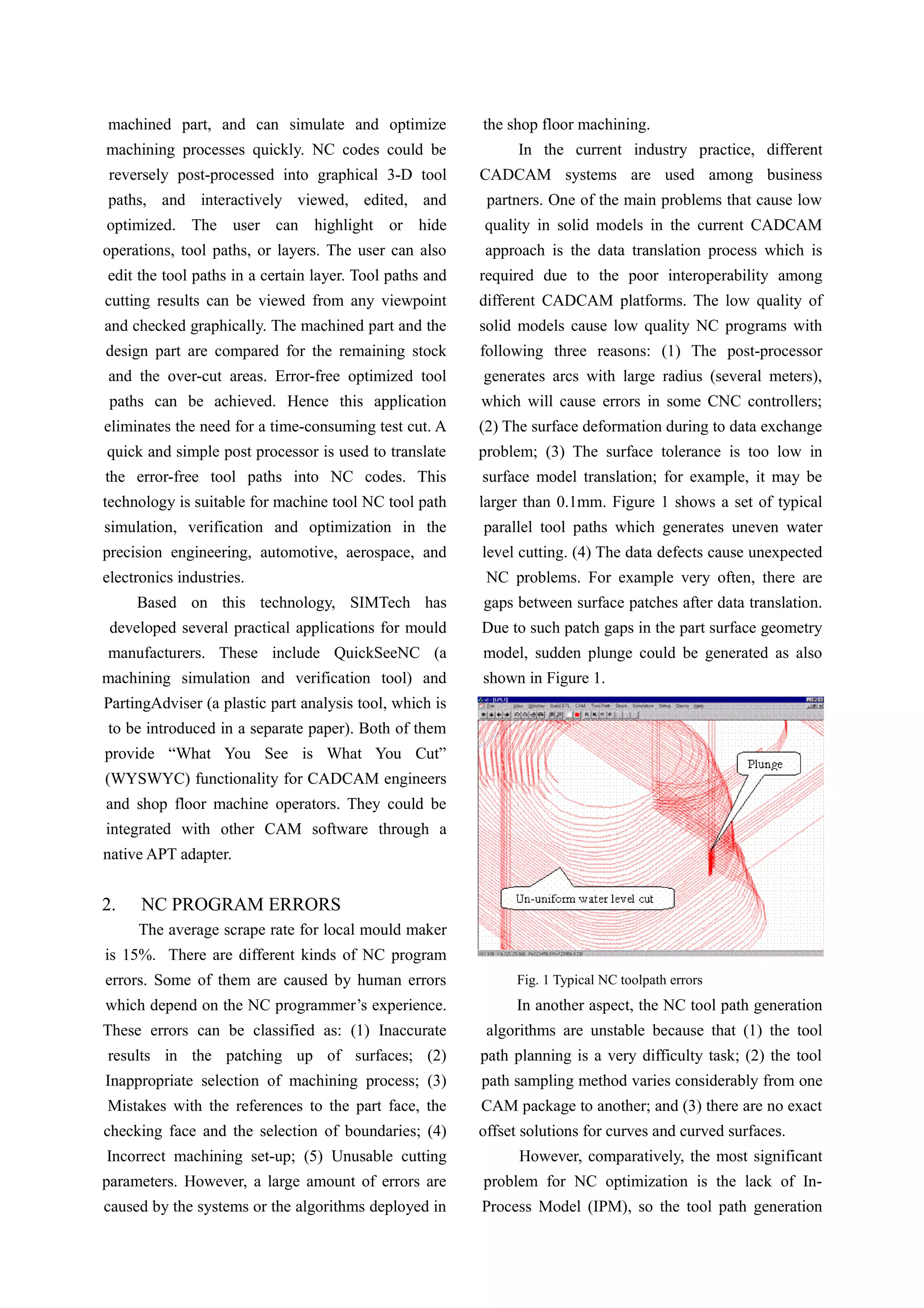
![with the CAM application does not consider the real
cutting geometry. This causes a lot of process
problems, such as air cut and gouging. It can be
observed that with the tool paths directly generated
from CAM application, the cutter moves through
remaining stock too fast, or too many conservative
air cuts in semi-finishing and finishing cut, or near-
touch cutting conditions occur which cause fast
cutter wearing. The recent development of high
speed machining (HSM) requires huge tool path in
order to realize the constant load. The constant load
is a very important factor in HSM. The cutter will
break under uneven cutting force. As the feed rate is
already very high, it does not reflect the sensitive
cutting situation to verify the NC program with the
traditional test cutting. It is highly demanded to
check the dynamic cutting forces before the
operation. Hence, there are strong requirements
from industry for a real dynamic simulation. The
simulation results can be used to optimize
feed/speed. Graphics-based visual tool path
checking is difficult as the tool path overlapping
with each other. Besides, it takes a long time to run
traditional simulation software.
3. FUNCTIONAL REQUIREMENTS FOR
AN IDEAL NC SIMULATOR
Theoretically, NC Simulation should feature
the full 3-D solid model of the entire NC machine
tool with detailed simulation for the manufacturing
(e.g. material removal) process. There are four
aspects to be covered by a comprehensive NC
simulator:
(1) NC tool path visualization. The simulator
enables programmers and machinists alike to
preview exactly what will happen on the machine,
especially for the cutter movements, or even for the
shop floor. Many users apply NC simulation for
electronic shop floor planning and documentation.
(2) NC verification. This function detects
problems in the NC tool path program. It is a
powerful visual inspection tool, which highlights
fast feed errors, gouges, and potential
crashes/collisions. Programmers can detect and
correct problems before prove-cut. Ideally, with NC
Verification you can virtually eliminate NC program
mistakes, greatly reduce the time spent on prove-
outs, and make the move to "lights-out" machining.
(3) NC analysis. This simulation function
identifies the tool path records responsible for an
error. You can quickly verify the dimensional
accuracy of the entire part with a full array of 3-D
measurement tools. NC analysis function compares
the simulated in-process part model to the designed
part model and checks if the machined part matches
to the design. One of the sub-function for NC
analysis is to perform constant gouge checking.
(4) NC optimization. This function
automatically determines the best feed rate for each
segment of the tool path based on the machining
conditions and amount of material removed.
Optimizing NC feed rates can greatly reduce the
time it takes to machine the part, assure the cutting
safety, and improve the quality of surface finish.
4. Quick NC SIMULATION METHODS
Z-Map [1] geometrical representation is widely
used for NC simulation verification. A map of Z values
represents the object geometry. Z-Map representation
can be effectively used for the surface that is always
visible from above in the direction parallel to the Z
axis. Since 3-axis milling parts are composed of
surfaces visible in the z direction, they can be
effectively expressed by the Z-Map representation.
With the Z-Map representation, the machining process
can be simulated by intersecting the Z-Map vectors
with the cutter profile.
Since the precision of Z-Map is decided mainly
by the XY resolution along the vertical walls, how
to increase the resolution along these walls and
reduce memory becomes a critical issue. An
important feature of 3-axis milling came into play.
Viewing from the top, the vertical walls only cover a
relatively small percentage of Z direction projection,
can we use finer resolution along the vertical walls
while maintain a rough resolution in the planar
area? This was the initial motivation for our
extended Z-Map method [2].](https://image.slidesharecdn.com/quick-nc-simulation-verification-for-high-speed-machining-160216080902/75/Quick-NC-simulation-verification-for-high-speed-machining-3-2048.jpg)
![paths, which can be further graphically displayed
and interactively viewed, edited, and optimized. The
user can highlight or hide an operation, tool path, or
layer. The user can also display and edit a certain
layer of the tool paths. Tool paths and cutting results
can be viewed from any viewpoint and checked
automatically. The machined part and the designed
part are compared for calculating the remaining
stock and any over cut. Error-free tool paths are
created, eliminating the need for a time-consuming
test cut. Quick and simple post processors are
developed to export the optimized tool paths into
NC codes.
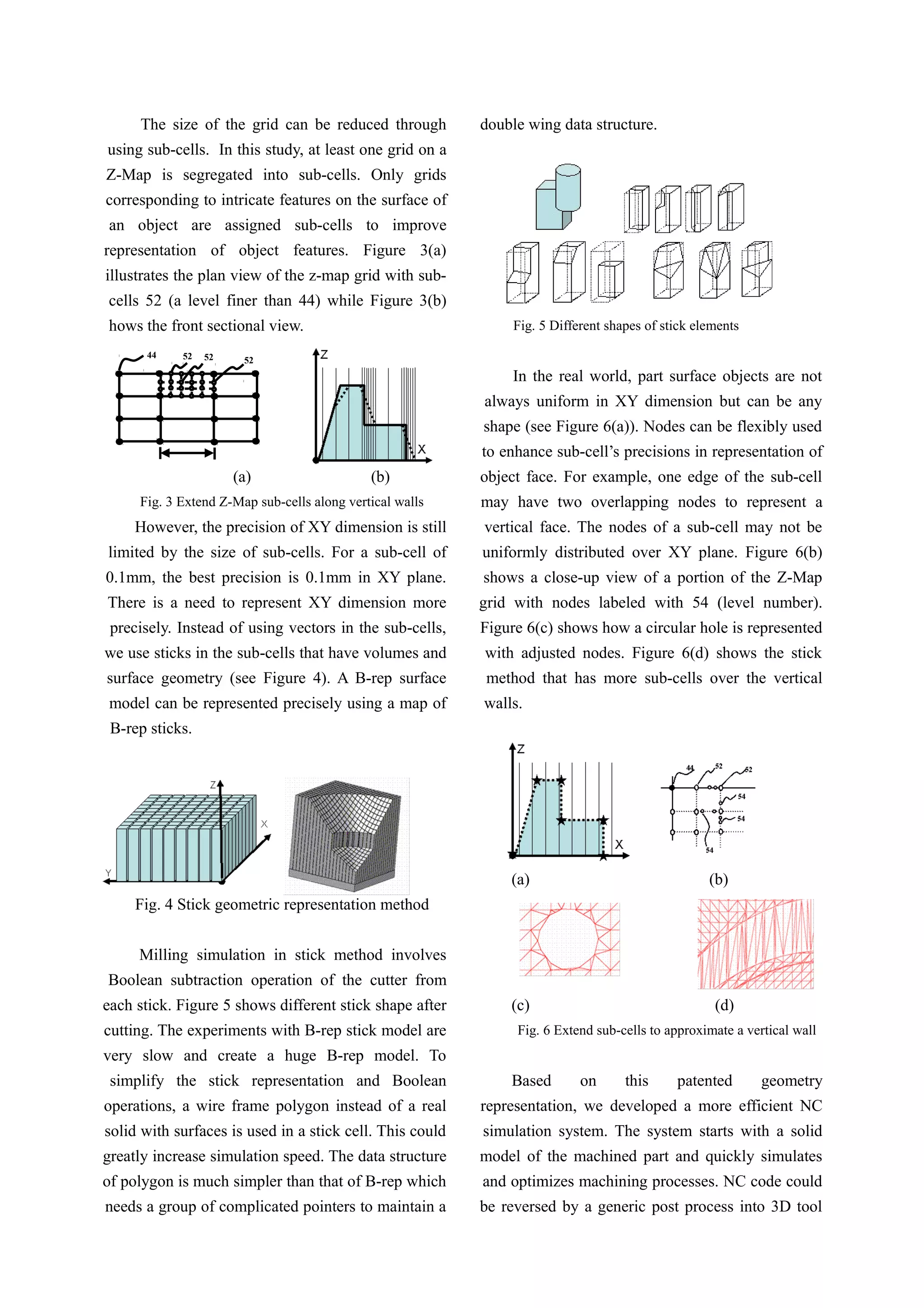
Figure 7 shows an application example of a
steel insert of ‘discman’ (a portable CD audio
player) mould from a company. There are 16
operations in this CLS file. The resulted NC codes
contains almost half million of NC blocks.
QuickSeeNC loaded in half million lines in seconds
and displayed tool paths in different colours
according to operations (see Figure 7-9).
NC Program Data Sheet core_insert_nc
No. Name Cutter SOL Time
1 V64C61CA D20.00 R0.000 L75 96m
2 V61CA1 D20.00 R0.000 L75 11m
3 V64C61CB D12.00 R6.000 L75 31m
4 V64C61CC D6.000 R3.000 L75 45m
5 V64C61CD D6.000 R3.000 L75 153m
6 V64C61CE D4.000 R2.000 L75 33m
7 V61CE1 D4.000 R2.000 L75 11m
8 V64C61CF D20.00 R0.000 L75 2m
9 V61CF1 D20.00 R0.000 L75 1m
10 V64C61CG D8.000 R0.000 L75 6m
11 V61CG1 D8.000 R0.000 L75 7m
12 V61CG2 D8.000 R0.000 L75 7m
13 V61CG3 D8.000 R0.000 L75 7m
14 V61CG4 D8.000 R0.000 L75 7m
15 V64C61CH D16.00R0.000 L75 13m
16 V61CH1 D16.00 R0.000 L75 14m
Total NC Program = 16
Machine time = 7 hours 23 minutes
Fig. 7 An example of 16 milling operations
Fig. 8 Toolpath of half million NC blocks
Fig. 9 Extended Z-Map simulation
Another patent [3] has been filed to use this
extended Z-Map representation for quick plastic
mould design and rapid tooling application. A CAD-
independent mould design toolkit has been
developed based on this patent.
Fig. 10 PartingAdviser for quick concept mold design
5. TOWARDS PERVASIVE SIMULATION
Despite the fact that simulations are becoming](https://image.slidesharecdn.com/quick-nc-simulation-verification-for-high-speed-machining-160216080902/75/Quick-NC-simulation-verification-for-high-speed-machining-5-2048.jpg)
![more widely used, there is a lack of integration of
simulations of manufacturing processes. Most work
focuses on an individual process being simulated.
Significant gaps remain in M&S technology –
particularly in the provision of a general in-process
model (IPM) that can be integrated across diverse
manufacturing processes [4]. To overcome the data
exchange problem between different models, we
extended the concept of the IPM from machining
process to other manufacturing process and intend to
develop a unified in-process geometrical model for
multiple machining and layered manufacturing
simulations. Figure 11 shows an application example
of a voxel model.
Fig. 11 Experiment result of voxel model
Further analyzing the voxel model, the authors of
this paper believe the voxel-based volume modeling is
a very promising approach to the unified IPM for
multiple machining and layered manufacturing (LM)
simulation [5-6]. As a natural clone of the LM
technology, the voxel model of an object and the object
fabricated using an LM closely resemble each other
since both are made of layers of small cells It
eliminates the STL format and eases accomplishments
of tasks such as estimation of errors in the physical
parameters of the fabricated objects, tolerance and
interference detection. Furthermore, voxel based
models permit the designer to analyze the LM object
and modify it at the voxel level leading to the design of
custom composites of arbitrary topology.
6. CONCLUSION
NC errors could destroy work pieces, even
damage machine tool. In the age of small batch
production, there is no time for trials and errors. The
challenges also come from huge tool path of HSM.
The traditional NC verification is so slow that even
HSM itself is faster than verification. The size of the
program combined with a high feed rate makes it
almost impossible to run test simulations prior to
cutting metal.
In this paper, we introduced our recent research
results on the quick NC simulation, which can
generate finished machining geometry efficiently
and accurately; at the same time, in-process cutting
volumes are calculated which allows for cutting
conditions optimization.
The novel hybrid multiple machining and
layered manufacturing processes posed a new
challenge to process planning and verification. It
seems that the voxel-based approach could be a
promising solution. More research work is to be
carried out. More detailed description will be
introduced in future papers.
Reference
1. R.B. Jerard, S.Z. Hussaini, R.L. Drysdale and
B. Schaudt, 1989, “Approximate methods for
simulation and verification of numerically
controlled machining programs”, Visual
Computer, 5(4), pp. 329–348.
2. P.L. Liu et al., 2002, An object representation
method, WO04032001A1
3. P.L. Liu et al., 2002, Mold design method and
system, WO04042481A1
4. www.imti21.org/msam/UnitProcess.pdf
5. Chandru, V., Manohar, S., Prakash, C. E.,
“Voxel-Based Modeling for Layered
Manufacturing”, IEEE Computer Graphics and
Applications (1995), v.15 n.6
6. Jang Donggo, Kim Kwangsoo, and Jung
Jungmin ,”Voxel-based Virtual Multi-axis
Machining”, International Journal of Advanced
Manufacturing Technology 16(10), 709-713,
2000](https://image.slidesharecdn.com/quick-nc-simulation-verification-for-high-speed-machining-160216080902/75/Quick-NC-simulation-verification-for-high-speed-machining-6-2048.jpg)
![more widely used, there is a lack of integration of
simulations of manufacturing processes. Most work
focuses on an individual process being simulated.
Significant gaps remain in M&S technology –
particularly in the provision of a general in-process
model (IPM) that can be integrated across diverse
manufacturing processes [4]. To overcome the data
exchange problem between different models, we
extended the concept of the IPM from machining
process to other manufacturing process and intend to
develop a unified in-process geometrical model for
multiple machining and layered manufacturing
simulations. Figure 11 shows an application example
of a voxel model.
Fig. 11 Experiment result of voxel model
Further analyzing the voxel model, the authors of
this paper believe the voxel-based volume modeling is
a very promising approach to the unified IPM for
multiple machining and layered manufacturing (LM)
simulation [5-6]. As a natural clone of the LM
technology, the voxel model of an object and the object
fabricated using an LM closely resemble each other
since both are made of layers of small cells It
eliminates the STL format and eases accomplishments
of tasks such as estimation of errors in the physical
parameters of the fabricated objects, tolerance and
interference detection. Furthermore, voxel based
models permit the designer to analyze the LM object
and modify it at the voxel level leading to the design of
custom composites of arbitrary topology.
6. CONCLUSION
NC errors could destroy work pieces, even
damage machine tool. In the age of small batch
production, there is no time for trials and errors. The
challenges also come from huge tool path of HSM.
The traditional NC verification is so slow that even
HSM itself is faster than verification. The size of the
program combined with a high feed rate makes it
almost impossible to run test simulations prior to
cutting metal.
In this paper, we introduced our recent research
results on the quick NC simulation, which can
generate finished machining geometry efficiently
and accurately; at the same time, in-process cutting
volumes are calculated which allows for cutting
conditions optimization.
The novel hybrid multiple machining and
layered manufacturing processes posed a new
challenge to process planning and verification. It
seems that the voxel-based approach could be a
promising solution. More research work is to be
carried out. More detailed description will be
introduced in future papers.
Reference
1. R.B. Jerard, S.Z. Hussaini, R.L. Drysdale and
B. Schaudt, 1989, “Approximate methods for
simulation and verification of numerically
controlled machining programs”, Visual
Computer, 5(4), pp. 329–348.
2. P.L. Liu et al., 2002, An object representation
method, WO04032001A1
3. P.L. Liu et al., 2002, Mold design method and
system, WO04042481A1
4. www.imti21.org/msam/UnitProcess.pdf
5. Chandru, V., Manohar, S., Prakash, C. E.,
“Voxel-Based Modeling for Layered
Manufacturing”, IEEE Computer Graphics and
Applications (1995), v.15 n.6
6. Jang Donggo, Kim Kwangsoo, and Jung
Jungmin ,”Voxel-based Virtual Multi-axis
Machining”, International Journal of Advanced
Manufacturing Technology 16(10), 709-713,
2000](https://image.slidesharecdn.com/quick-nc-simulation-verification-for-high-speed-machining-160216080902/75/Quick-NC-simulation-verification-for-high-speed-machining-7-2048.jpg)

The paper presents a novel high-speed numerical control (NC) simulation method aimed at improving accuracy and efficiency in machining processes, addressing issues caused by traditional NC verification techniques that struggle with high-speed operations. The introduced method utilizes an extended z-map approach, allowing for better dynamic load calculations and quicker simulation of complex toolpaths, thereby reducing errors and enhancing profitability in manufacturing. It highlights the importance of integrating simulation methods across diverse manufacturing processes to optimize efficiency and produce error-free outcomes.


![Food Processing Brochure 060316[1]](https://cdn.slidesharecdn.com/ss_thumbnails/foodprocessingbrochure0603161-12634188295119-phpapp02-thumbnail.jpg?width=640&height=640&fit=bounds)