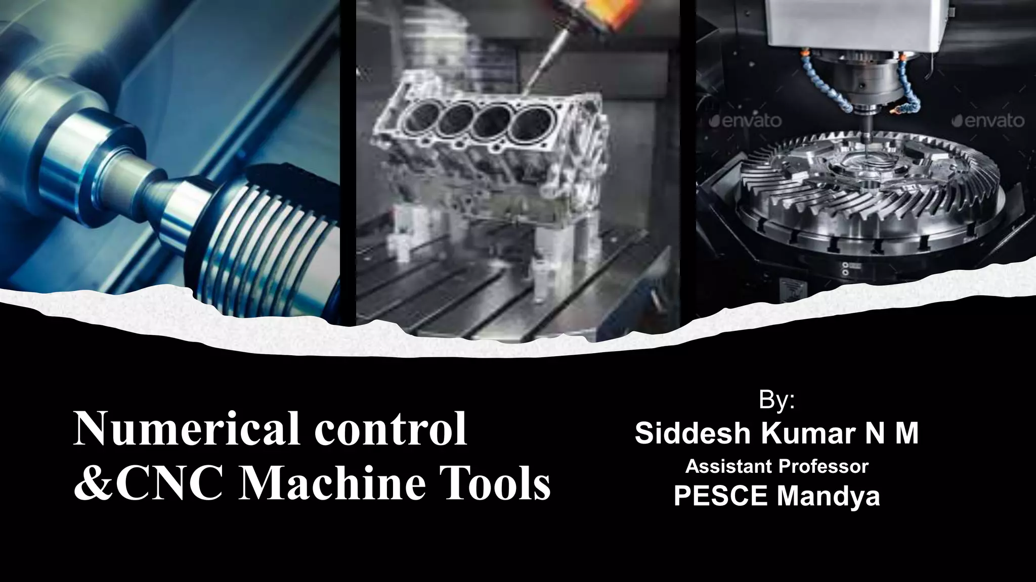
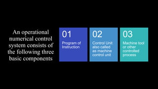
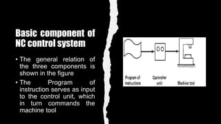
Numerical control
&CNC Machine Tools
By:
Siddesh Kumar N M
Assistant Professor
PESCE Mandya
Basic
component of
NC Systems
An operational
numerical control
system consists of
the following three
basic components
Program of
Instruction
01
Control Unit
also called
as machine
control unit
02
Machine tool
or other
controlled
process
03
Basic component of
NC control system
• The general relation of
the three components is
shown in the figure
• The Program of
instruction serves as input
to the control unit, which
in turn commands the
machine tool
Program of
Instructions
• It’s the detail step by step set of directions
which tell the machine tool what to do
• It is coded in numerical or symbolic form on
some type of input medium that can be
interpreted by the control unit
• The most common input device is 1-in. wide
tape, in older days other form of input media
includes punched cards, magnetic tape and
even motion picture film
• There are two methods of input to the NC
system
• MDI(Manual data input)
Program of
Instructions
There are two methods of input to the NC
system
MDI(Manual data input)
• In MDI the data is entered manually
• MDI is an appropriate method
• Suitable for particular type of production
unit where change in design is not much
required
DNC(Direct numerical control)
• The program of instructions are prepared
by some called part programmer
• The programmer job is to provide a set of
detailed instruction
Controller
Unit
•This consits of the electronics and hardware that
read and interpret the program of instruction, which
converts the input into mechanical actions of the
machine tool
•Elements of controller unit includes the tape
reader, data buffer, signal output channels to the
machine tool, feed back channel etc.
•In modern NC systems micro computer is used as
a control unit
•Tape reader is an electromechanical device for
winding and reading the punched tape
Controller
Unit
•The data contained on the tape are read into the
data buffer.
•The purpose of the device is to store the input
instruction in logical form of instruction
•A block of instructions usually represents one
complete set of infromation
•The signal output channels are connected to the
servomotors and other controls in the machine
tools
•Through these channels the instruction are sent to
the machine tool, feed back unit will be present to
Machine
tool
•This is the system which performs the useful work
•The machine tool consists of the work table and
spindle as well as motors and controls necessary to
drive them
•It also includes cutting tools, work fixture and other
auxillary equipments
NC Procedure
Steps to be
accomplished
to utilize NC in
manufacturing
Process
planning
Part
programming
Tape
preparation
Tape
verification
Production
Process planning
• The engineering drawing of the
workpart must be interpreted in
terms of the manufacturing process
• It is concerned with the preparation
of a route sheet
• The route is listing of sequence
operations to be performed
Part
Programming
• Part programmer plans the process for the portions of the
job to be accomplished
• Part programmer shloud be knowledgeable about the
machining process and they have been trained for NC
• The two ways to program of NC are
Manual part programming
• The machining instructions are prepared on a form called
as part program manuscript
• Part program manuscript is a listing of the relative
cutter/workpiece position must be followed
Computer assisted part Programming
• In this computer is used for programming which saves a lot
of time and money
Tape
preparation
• A punched tape is prepared from the part
programmer's NC process plan
• In manual part programming, the puncehd tape
is prepared directly from the part program
manuscript
• In computer assisted part programming, the
computer interprets the list of part programming
instruction
• Computer performs the calculation to covert this
into a detailed set of machine tool motion
Tape
verification
• After the punched tape has been
prepared, a method is usually provided
for checking the accuracy of the tape
• Sometimes the tape is running it through
a computer program which plots the
various tool movement
• A foam or plastic material is sometimes
used for verification
• Programming errors are not uncommon
Production
• This involves ordering the raw workparts,
speifying and preparing the tooling and
any special fixtures
• The machine tool operators function
during production is to load the raw
workpart in the machine
• When the part is completed, the operator
removes it from the machine and loads
the next part
Coordinate System
Coordinate
systems
• Two axes X and Y are defined in
the plane of the table as shown
• The z axis is perpendicular to this
plane and movement in the Z
direction is controlled by the
vertical motion of the spindle
• The positive and negative direction
of the motion of tool relative to
table along these axes is shown
• NC drilling press are classified into
two axis or three axis machine
depending on the capability to
control z axis
Right hand rule
• Three rotational axes are defined
in NC
• The a, b & c axes, these axes
specify about X, Y & Z axes
respecively
• To differentiate the positive and
negative angular motions the
RIGHT HAND RULE can be
used
• Using right hand rule with the
thumb pointing in the positive
linear rotational direction
Coordinate
system
• For turning operation, two axes
are normally required to
command the movement of the
tool
• The Z axis is the axis of rotation
of the workpiece
• The main purpose of the co
ordinate system is to provide a
means of locationg the tool in
relation to the workpiece
NC motion control
system
NC motion control system
The basic types of motion control system are as follows
• Point-to-point
• Straight cut
• Contouring
Point to point system represt the lowest level of motion control
between the tool and workpiece. Contouring represents the
highest level of control
Point to point
NC (PTP)
• It is also called as positioning
system
• In PTP the objective of the machine
tool is to move the cutting tool to a
predefined location
• The speed or path is not important
• Once the tool reaches the desired
position the machining operation is
performed
Point to point
NC
• NC drill presses are good example of PTP
system
• The spindle must be positioned at a particular
location on the workpiece
• Then the drilling of the hole is performed
• No need of controlling the speed of the
relative motion
• These are simplest tools and less expensive
• For drilling and spot welding PTP is best
suited where higher level control is not
necessary
Straight cut NC
• Straight cut control systems are capable of moving the cutting
tool parallel to one of the major axes at the controlled rate
• It is not possible to combine movements in more than a single
axis direction
• Angular cuts on the workpiece is not possible
Contouring NC
• Contouring is most complex, the most flexible and the most expensive type
of machine tool control
• The motion can be controlled in more than one axis simultaneously
• The path of the cutter is continuously controlled to generate the desired
geometry
• It is also called as continuous path NC system
• Straight, plane surface at any orientation, circular paths, conical shapes and
any shapes can be defined in contouring
• Milling and turning operations are common example
Contouring NC
• In order to obtain the curved geometry, the segments are braked
into many number of lines (very short lines)
• The tool is commanded to machine each segment in succession
• Results in the curve geometry inside and outside tolerance are
predefined and tolerance bands are maintained
Advantages &
Limitations of NC
Advantages of NC
• Greater manufacturing flexibility – NC can easily adapt to the engineering design changes
and a shift in the production schedule.
• Reduced manufacturing lead time – the job can easily and quickly set up with NC.
• Reduced non-productive time – In case of complex machining NC seems helpful to reduce
the non-productive time. Because of quick/ automatic tool changing, quick setting up, and
reduced workpiece handling time.
• Reduced fixturing – the fixture required in NC operation are simpler and less costly
because NC tape does positioning instead of jig and fixture.
• Reduced inventory - this is the result of fewer setup reduced lead time.
• Quality control improved – No risk of human mistakes. It produces the part with high
accuracy. It also reduce the man-hour for inspection.
• Greater operator safety.
• Reduce the scrap – the high accuracy of NC machine helps to reduce scrap material.
• Reduced floor space requirement – since the one NC can do variety of operation it
replaces several conventional machines.
Limitations of NC
• High investment cost and Maintenance cost –
most complex and sophisticated technology cost
more than the conventional machine.
• Require skilled operator – finding and training of
NC personnel should be considered.
• Tearing and wearing of punch tape and less
reliable punch tape component.
• Part programming mistake in punched tape.
• No optimal feed and speed – conventional NC
machine does not provide an option to change the
cutting speed and feed during the operation.
Application of
NC
Applications of NC
• The NC technology is suitable to sequence/series of machining
process.
• Job geometry is complex, expensive. Mistakes in the process
lead to high loss.
• It is expected engineering design changes in future.
• High metal removal is required.
• The work part required 100% inspection.
• There must be close tolerance on work part.
• When many operations need to be done when processing. It is
frequently processed in batches of small lot sizes.
Thank you
Reference
CAD/CAM Computer Aided Design and Manufacturing by M Groover & E.
Zimmers

Numerical Control

  • 1.
    Numerical control &CNC MachineTools By: Siddesh Kumar N M Assistant Professor PESCE Mandya
  • 2.
  • 3.
    An operational numerical control systemconsists of the following three basic components Program of Instruction 01 Control Unit also called as machine control unit 02 Machine tool or other controlled process 03
  • 4.
    Basic component of NCcontrol system • The general relation of the three components is shown in the figure • The Program of instruction serves as input to the control unit, which in turn commands the machine tool
  • 5.
    Program of Instructions • It’sthe detail step by step set of directions which tell the machine tool what to do • It is coded in numerical or symbolic form on some type of input medium that can be interpreted by the control unit • The most common input device is 1-in. wide tape, in older days other form of input media includes punched cards, magnetic tape and even motion picture film • There are two methods of input to the NC system • MDI(Manual data input)
  • 6.
    Program of Instructions There aretwo methods of input to the NC system MDI(Manual data input) • In MDI the data is entered manually • MDI is an appropriate method • Suitable for particular type of production unit where change in design is not much required DNC(Direct numerical control) • The program of instructions are prepared by some called part programmer • The programmer job is to provide a set of detailed instruction
  • 7.
    Controller Unit •This consits ofthe electronics and hardware that read and interpret the program of instruction, which converts the input into mechanical actions of the machine tool •Elements of controller unit includes the tape reader, data buffer, signal output channels to the machine tool, feed back channel etc. •In modern NC systems micro computer is used as a control unit •Tape reader is an electromechanical device for winding and reading the punched tape
  • 8.
    Controller Unit •The data containedon the tape are read into the data buffer. •The purpose of the device is to store the input instruction in logical form of instruction •A block of instructions usually represents one complete set of infromation •The signal output channels are connected to the servomotors and other controls in the machine tools •Through these channels the instruction are sent to the machine tool, feed back unit will be present to
  • 9.
    Machine tool •This is thesystem which performs the useful work •The machine tool consists of the work table and spindle as well as motors and controls necessary to drive them •It also includes cutting tools, work fixture and other auxillary equipments
  • 10.
  • 11.
    Steps to be accomplished toutilize NC in manufacturing Process planning Part programming Tape preparation Tape verification Production
  • 12.
    Process planning • Theengineering drawing of the workpart must be interpreted in terms of the manufacturing process • It is concerned with the preparation of a route sheet • The route is listing of sequence operations to be performed
  • 13.
    Part Programming • Part programmerplans the process for the portions of the job to be accomplished • Part programmer shloud be knowledgeable about the machining process and they have been trained for NC • The two ways to program of NC are Manual part programming • The machining instructions are prepared on a form called as part program manuscript • Part program manuscript is a listing of the relative cutter/workpiece position must be followed Computer assisted part Programming • In this computer is used for programming which saves a lot of time and money
  • 14.
    Tape preparation • A punchedtape is prepared from the part programmer's NC process plan • In manual part programming, the puncehd tape is prepared directly from the part program manuscript • In computer assisted part programming, the computer interprets the list of part programming instruction • Computer performs the calculation to covert this into a detailed set of machine tool motion
  • 15.
    Tape verification • After thepunched tape has been prepared, a method is usually provided for checking the accuracy of the tape • Sometimes the tape is running it through a computer program which plots the various tool movement • A foam or plastic material is sometimes used for verification • Programming errors are not uncommon
  • 16.
    Production • This involvesordering the raw workparts, speifying and preparing the tooling and any special fixtures • The machine tool operators function during production is to load the raw workpart in the machine • When the part is completed, the operator removes it from the machine and loads the next part
  • 17.
  • 18.
    Coordinate systems • Two axesX and Y are defined in the plane of the table as shown • The z axis is perpendicular to this plane and movement in the Z direction is controlled by the vertical motion of the spindle • The positive and negative direction of the motion of tool relative to table along these axes is shown • NC drilling press are classified into two axis or three axis machine depending on the capability to control z axis
  • 19.
    Right hand rule •Three rotational axes are defined in NC • The a, b & c axes, these axes specify about X, Y & Z axes respecively • To differentiate the positive and negative angular motions the RIGHT HAND RULE can be used • Using right hand rule with the thumb pointing in the positive linear rotational direction
  • 20.
    Coordinate system • For turningoperation, two axes are normally required to command the movement of the tool • The Z axis is the axis of rotation of the workpiece • The main purpose of the co ordinate system is to provide a means of locationg the tool in relation to the workpiece
  • 21.
  • 22.
    NC motion controlsystem The basic types of motion control system are as follows • Point-to-point • Straight cut • Contouring Point to point system represt the lowest level of motion control between the tool and workpiece. Contouring represents the highest level of control
  • 23.
    Point to point NC(PTP) • It is also called as positioning system • In PTP the objective of the machine tool is to move the cutting tool to a predefined location • The speed or path is not important • Once the tool reaches the desired position the machining operation is performed
  • 24.
    Point to point NC •NC drill presses are good example of PTP system • The spindle must be positioned at a particular location on the workpiece • Then the drilling of the hole is performed • No need of controlling the speed of the relative motion • These are simplest tools and less expensive • For drilling and spot welding PTP is best suited where higher level control is not necessary
  • 25.
    Straight cut NC •Straight cut control systems are capable of moving the cutting tool parallel to one of the major axes at the controlled rate • It is not possible to combine movements in more than a single axis direction • Angular cuts on the workpiece is not possible
  • 26.
    Contouring NC • Contouringis most complex, the most flexible and the most expensive type of machine tool control • The motion can be controlled in more than one axis simultaneously • The path of the cutter is continuously controlled to generate the desired geometry • It is also called as continuous path NC system • Straight, plane surface at any orientation, circular paths, conical shapes and any shapes can be defined in contouring • Milling and turning operations are common example
  • 27.
    Contouring NC • Inorder to obtain the curved geometry, the segments are braked into many number of lines (very short lines) • The tool is commanded to machine each segment in succession • Results in the curve geometry inside and outside tolerance are predefined and tolerance bands are maintained
  • 28.
  • 29.
    Advantages of NC •Greater manufacturing flexibility – NC can easily adapt to the engineering design changes and a shift in the production schedule. • Reduced manufacturing lead time – the job can easily and quickly set up with NC. • Reduced non-productive time – In case of complex machining NC seems helpful to reduce the non-productive time. Because of quick/ automatic tool changing, quick setting up, and reduced workpiece handling time. • Reduced fixturing – the fixture required in NC operation are simpler and less costly because NC tape does positioning instead of jig and fixture. • Reduced inventory - this is the result of fewer setup reduced lead time. • Quality control improved – No risk of human mistakes. It produces the part with high accuracy. It also reduce the man-hour for inspection. • Greater operator safety. • Reduce the scrap – the high accuracy of NC machine helps to reduce scrap material. • Reduced floor space requirement – since the one NC can do variety of operation it replaces several conventional machines.
  • 30.
    Limitations of NC •High investment cost and Maintenance cost – most complex and sophisticated technology cost more than the conventional machine. • Require skilled operator – finding and training of NC personnel should be considered. • Tearing and wearing of punch tape and less reliable punch tape component. • Part programming mistake in punched tape. • No optimal feed and speed – conventional NC machine does not provide an option to change the cutting speed and feed during the operation.
  • 31.
  • 32.
    Applications of NC •The NC technology is suitable to sequence/series of machining process. • Job geometry is complex, expensive. Mistakes in the process lead to high loss. • It is expected engineering design changes in future. • High metal removal is required. • The work part required 100% inspection. • There must be close tolerance on work part. • When many operations need to be done when processing. It is frequently processed in batches of small lot sizes.
  • 33.
    Thank you Reference CAD/CAM ComputerAided Design and Manufacturing by M Groover & E. Zimmers