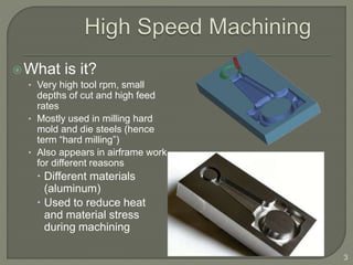
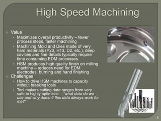
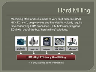
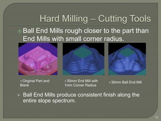
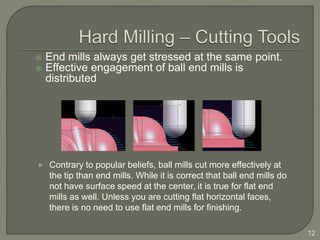
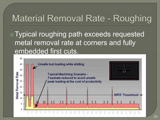
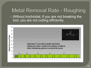
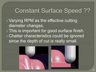
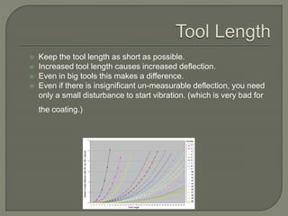
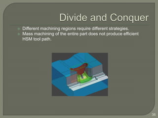
Submitted By:
SACHIN KUMAR SUNDRAM
1713240079
Seminar
On
High Speed Machining
(HSM)
Introduction and Background
HSM / Hard Milling
Components of HSM
HSM aspects outside your CAM
system
HSM aspects inside your CAM
system
References
2
What is it?
• Very high tool rpm, small
depths of cut and high feed
rates
• Mostly used in milling hard
mold and die steels (hence
term “hard milling”)
• Also appears in airframe work
for different reasons
 Different materials
(aluminum)
 Used to reduce heat
and material stress
during machining
3
 Value
• Maximizes overall productivity – fewer
process steps, faster machining
• Machining Mold and Dies made of very
hard materials (P20, H13, D2, etc.), deep
cavities and fine details typically require
time consuming EDM processes.
• HSM produces high quality finish on milling
machine – reduces need for EDM
electrodes, burning and hand finishing
 Challenges
• How to drive HSM machines to capacity
without breaking tools
• Tool makers cutting data ranges from very
safe to highly optimistic - “what data do we
use and why doesn’t this data always work for
me?”
4
7
Machining Mold and Dies made of very hard materials (P20,
H13, D2, etc.), deep cavities and fine details typically require
time consuming EDM processes. HSM helps users bypass
EDM with out-of-the-box “hard-milling” solutions.
“It is only as good as the weakest link.”
HSM - High Efficiency Hard Milling
HSM Capable
Machine Tool Cutting Tool Controller
HSM capable
CAM System
Programming
Know-how
 Do you have all the components you need?
 Increasing spindle speed and feed while
decreasing chip load is just the beginning step
of successful high speed programming.
 Further understanding of the cutting action is
essential. (chatter, vertical engagement angle,
material removal rate, effect of surface speed
on the finish, etc.)
8
 A stable machine capable of running at
high speeds and feeds without the
machine dynamics coming into the
machining equation.
 The cutting forces and vibration caused by
the actual contact between the tool and the
material becomes the primary action.
 High Speed Spindle retrofits are not High
Speed Machines.
9
HSM Capable
Machine Tool
 Tools capable of handling very high surface temperature.
 Available High Length to Diameter ratios for reaching into
intricate cavities
TiN
Gold coating
High surface hardness
Lubricity
TiCN
Blue-gray coating
Moderate temperatures
TiAlN
High Temperature applications
Forms Al Oxide coating -low thermal conductivity
Longer tool life
Cutting Tool
 Ball End Mills rough closer to the part than
End Mills with small corner radius.
11
30mm End Mill with
1mm Corner Radius
30mm Ball End MillOriginal Part and
Blank
 Ball End Mills produce consistent finish along the
entire slope spectrum.
 End mills always get stressed at the same point.
 Effective engagement of ball end mills is
distributed
12
 Contrary to popular beliefs, ball mills cut more effectively at
the tip than end mills. While it is correct that ball end mills do
not have surface speed at the center, it is true for flat end
mills as well. Unless you are cutting flat horizontal faces,
there is no need to use flat end mills for finishing.
Holders capable of very low run-out
at high spindle speeds and
acceleration.
• HSK
• Shrink fit
• ‘Tribos’
Dynamic vs. static run-out.
Example holder standards. 3Gs
13
 Support for various high speed interpolation
types
 Look-ahead
 Corner acceleration and deceleration
curves.
 Distinction criteria for Linear Vs Spline
interpolation.
 NURBS (Non-Uniformal Rational B-Spline)
Non-Uniform Rational B-Spline: This is a mathematical representation for smooth curves and surfaces. A
type of curve or surface for which the delta (difference) between successive knots need not be
expressed in uniform increments of 1. This non-uniformity distinguishes NURBS from other curve
types.
B-Spline: A particularly smooth class of approximating curves. B-Splines are fully approximating: such a
curve generally passes through its control points if several of them are in the same location. B-Spline
curves are converted to NURBS curves when imported into Industrial Design softwares for example
3D Studio MAX.
Controller
Smooth Interpolation
16
Exact positioning
 Discrepancy between actual and requested
high feed rate.
 Is SuperGI (Geometric Intelligence) or similar
algorithm turned on ?
 Is SuperGI disabled due to programming/post
errors?
• Subroutines within a Super GIMakino block
• Cutter Compensation
 Using multiple Super GI modes for finishing,
roughing and non-cutting moves (M250,
M251, M252Makino)
18
Bi-directional copy-mill example
 Consistent use of chatter free machining
parameters.
 Do not exceed the intended Metal Removal Rate.
 Leave uniform amount of stock after every tool.
 Consistent finish in both steep and non-steep areas.
 Smooth, continuous cutting.
 Fine tuned HSM data for CNC controllers
 Divide and conquer. Do not apply templates to the
entire part.
19
HSM capable
CAM System
Programming
Know-how
 Chatter is the #2 cause of tool failure
in hard milling applications. (It is also
the most overlooked)
 Process for avoiding chatter
20
Chatter Zone
21
Integrated, customizable
machining database enables
storing, retrieving and
associatively using the data in tool
path operations.
NX-CAM for example includes
proven machining data for
commonly used raw materials.
P20 in NX3
More materials coming up in NX4.
 Avoid over-loading the tool while maintaining high feed
rates
 Controlling tool step-over, managing tool embedding
• Z-level plus path
• Enhanced trochoidal paths
 Efficiently locate the optimum machining areas
 Use the in-process workpiece
22
The key issue is achieving a constant rate of material removal
23
Typical roughing path exceeds requested
metal removal rate at corners and fully
embedded first cuts.
24
 Without trochoidal, if you are not breaking the
tool, you are not cutting efficiently.
25
26
27
Order your flowcuts
28
Cut between your Z-Levels
29
Easy control of vertical and horizontal
engagement angles.
Z-lock provides much better Super-GI
performance at the controller.
30
Watch out for Z level passes near horizontal corners.
On part stepover option enables constant metal
removal rate and uniform surface finish
31
Too many engages and retracts are
unsafe and should be avoided.
Level based Rest Milling is faster too.
32
Varying RPM as the effective cutting
diameter changes.
This is important for good surface finish.
Chatter characteristics could be ignored
since the depth of cut is really small.
34
 Keep the tool length as short as possible.
 Increased tool length causes increased deflection.
 Even in big tools this makes a difference.
 Even if there is insignificant un-measurable deflection, you need
only a small disturbance to start vibration. (which is very bad for
the coating.)
 Different machining regions require different strategies.
 Mass machining of the entire part does not produce efficient
HSM tool path.
36
 https://www.ctemag.com/news/articles/what-high-speed-
machining
 https://www.harveyperformance.com/in-the-loupe/high-
efficiency-milling-vs-high-speed-machining
 https://www.kellertechnology.com/blog/high-speed-
machining-101/
 https://www.controleng.com/articles/high-speed-
machining-provides-dynamic-accuracy-to-machine-tools/
38

Mech high speed machining (hsm) ppt

  • 1.
    Submitted By: SACHIN KUMARSUNDRAM 1713240079 Seminar On High Speed Machining (HSM)
  • 2.
    Introduction and Background HSM/ Hard Milling Components of HSM HSM aspects outside your CAM system HSM aspects inside your CAM system References 2
  • 3.
    What is it? •Very high tool rpm, small depths of cut and high feed rates • Mostly used in milling hard mold and die steels (hence term “hard milling”) • Also appears in airframe work for different reasons  Different materials (aluminum)  Used to reduce heat and material stress during machining 3
  • 4.
     Value • Maximizesoverall productivity – fewer process steps, faster machining • Machining Mold and Dies made of very hard materials (P20, H13, D2, etc.), deep cavities and fine details typically require time consuming EDM processes. • HSM produces high quality finish on milling machine – reduces need for EDM electrodes, burning and hand finishing  Challenges • How to drive HSM machines to capacity without breaking tools • Tool makers cutting data ranges from very safe to highly optimistic - “what data do we use and why doesn’t this data always work for me?” 4
  • 5.
    7 Machining Mold andDies made of very hard materials (P20, H13, D2, etc.), deep cavities and fine details typically require time consuming EDM processes. HSM helps users bypass EDM with out-of-the-box “hard-milling” solutions. “It is only as good as the weakest link.” HSM - High Efficiency Hard Milling HSM Capable Machine Tool Cutting Tool Controller HSM capable CAM System Programming Know-how
  • 6.
     Do youhave all the components you need?  Increasing spindle speed and feed while decreasing chip load is just the beginning step of successful high speed programming.  Further understanding of the cutting action is essential. (chatter, vertical engagement angle, material removal rate, effect of surface speed on the finish, etc.) 8
  • 7.
     A stablemachine capable of running at high speeds and feeds without the machine dynamics coming into the machining equation.  The cutting forces and vibration caused by the actual contact between the tool and the material becomes the primary action.  High Speed Spindle retrofits are not High Speed Machines. 9 HSM Capable Machine Tool
  • 8.
     Tools capableof handling very high surface temperature.  Available High Length to Diameter ratios for reaching into intricate cavities TiN Gold coating High surface hardness Lubricity TiCN Blue-gray coating Moderate temperatures TiAlN High Temperature applications Forms Al Oxide coating -low thermal conductivity Longer tool life Cutting Tool
  • 9.
     Ball EndMills rough closer to the part than End Mills with small corner radius. 11 30mm End Mill with 1mm Corner Radius 30mm Ball End MillOriginal Part and Blank  Ball End Mills produce consistent finish along the entire slope spectrum.
  • 10.
     End millsalways get stressed at the same point.  Effective engagement of ball end mills is distributed 12  Contrary to popular beliefs, ball mills cut more effectively at the tip than end mills. While it is correct that ball end mills do not have surface speed at the center, it is true for flat end mills as well. Unless you are cutting flat horizontal faces, there is no need to use flat end mills for finishing.
  • 11.
    Holders capable ofvery low run-out at high spindle speeds and acceleration. • HSK • Shrink fit • ‘Tribos’ Dynamic vs. static run-out. Example holder standards. 3Gs 13
  • 12.
     Support forvarious high speed interpolation types  Look-ahead  Corner acceleration and deceleration curves.  Distinction criteria for Linear Vs Spline interpolation.  NURBS (Non-Uniformal Rational B-Spline) Non-Uniform Rational B-Spline: This is a mathematical representation for smooth curves and surfaces. A type of curve or surface for which the delta (difference) between successive knots need not be expressed in uniform increments of 1. This non-uniformity distinguishes NURBS from other curve types. B-Spline: A particularly smooth class of approximating curves. B-Splines are fully approximating: such a curve generally passes through its control points if several of them are in the same location. B-Spline curves are converted to NURBS curves when imported into Industrial Design softwares for example 3D Studio MAX. Controller
  • 14.
  • 15.
     Discrepancy betweenactual and requested high feed rate.  Is SuperGI (Geometric Intelligence) or similar algorithm turned on ?  Is SuperGI disabled due to programming/post errors? • Subroutines within a Super GIMakino block • Cutter Compensation  Using multiple Super GI modes for finishing, roughing and non-cutting moves (M250, M251, M252Makino) 18 Bi-directional copy-mill example
  • 16.
     Consistent useof chatter free machining parameters.  Do not exceed the intended Metal Removal Rate.  Leave uniform amount of stock after every tool.  Consistent finish in both steep and non-steep areas.  Smooth, continuous cutting.  Fine tuned HSM data for CNC controllers  Divide and conquer. Do not apply templates to the entire part. 19 HSM capable CAM System Programming Know-how
  • 17.
     Chatter isthe #2 cause of tool failure in hard milling applications. (It is also the most overlooked)  Process for avoiding chatter 20 Chatter Zone
  • 18.
    21 Integrated, customizable machining databaseenables storing, retrieving and associatively using the data in tool path operations. NX-CAM for example includes proven machining data for commonly used raw materials. P20 in NX3 More materials coming up in NX4.
  • 19.
     Avoid over-loadingthe tool while maintaining high feed rates  Controlling tool step-over, managing tool embedding • Z-level plus path • Enhanced trochoidal paths  Efficiently locate the optimum machining areas  Use the in-process workpiece 22 The key issue is achieving a constant rate of material removal
  • 20.
  • 21.
    Typical roughing pathexceeds requested metal removal rate at corners and fully embedded first cuts. 24
  • 22.
     Without trochoidal,if you are not breaking the tool, you are not cutting efficiently. 25
  • 23.
  • 24.
  • 25.
  • 26.
  • 27.
    Easy control ofvertical and horizontal engagement angles. Z-lock provides much better Super-GI performance at the controller. 30 Watch out for Z level passes near horizontal corners.
  • 28.
    On part stepoveroption enables constant metal removal rate and uniform surface finish 31
  • 29.
    Too many engagesand retracts are unsafe and should be avoided. Level based Rest Milling is faster too. 32
  • 30.
    Varying RPM asthe effective cutting diameter changes. This is important for good surface finish. Chatter characteristics could be ignored since the depth of cut is really small. 34
  • 31.
     Keep thetool length as short as possible.  Increased tool length causes increased deflection.  Even in big tools this makes a difference.  Even if there is insignificant un-measurable deflection, you need only a small disturbance to start vibration. (which is very bad for the coating.)
  • 32.
     Different machiningregions require different strategies.  Mass machining of the entire part does not produce efficient HSM tool path. 36
  • 33.
     https://www.ctemag.com/news/articles/what-high-speed- machining  https://www.harveyperformance.com/in-the-loupe/high- efficiency-milling-vs-high-speed-machining https://www.kellertechnology.com/blog/high-speed- machining-101/  https://www.controleng.com/articles/high-speed- machining-provides-dynamic-accuracy-to-machine-tools/
  • 34.