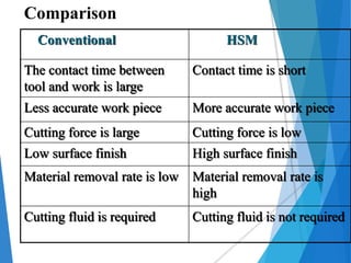
A
Seminar
On
“HIGH SPEED MACHINING”
Presented by
MR. Vaibhav V Chopade
Under the Guidance of
Prof. P. R. DABHADE
Department of Mechanical Engineering
Siddhivinayak Technical Campus, School of Polytechnic
& Research Technology Shegaon,
Dist- Buldhana – 444 203 (Maharashtra)
2017-18
CONTENTS
 Introduction
 Machining system
 Demands on the machine
 Application areas
 Comparison
 Advantages
 Disadvantages
 Conclusion
INTRODUCTION
 High cutting speed machining
 High rotational speed machining
 High feed machining
 High speed and feed machining
 High productive machining
Finally,
“HSM is a powerful machining method that
combines high feed rates with high spindle
speeds, specific tools and specific tool motion.”
MACHINING SYSTEM
 MACHINE TOOLS
 3-axis horizontal and vertical milling
machines
 CNC 4-axis milling machine offers the
option of tilting the milling cutters to
improve the cutting conditions
 5-axis machine with inter changeable
spindle units allow to rough, semi finish
and finish with a single set up.
CUTTING TOOLS
 TiN and TiCN coated Carbide for
materials with hardness less than 42 HRC
 TiALN coated Carbide for materials with
hardness 42 HRC and above
 For special applications like hard turning
(HRC 60-65) PCBN is used
 Cubic boron nitrite (CBN) and ceramic for
cast iron
 Poly crystalline diamonds (PCD) and
Cermets are used for aluminum
Toolholder & Tool Unbalance
Problem
 HSK
 Dynamic vs. static
run-out.
 Shrink fit
 ‘Tribos’
TOOL HOLDERS AND COLLET
1) ColletS
Triboss Run-out
DEMANDS ON THE MACHINE
 Spindle speed range <=40000 rpm
 Spindle power >22 KW
 Programmable feed rate 40-60 m/min
 Rapid travels <90 m/min
 Block processing speed 1-20 ms
 High thermal stability and rigidity in spindle
 Air blast/coolant through spindle
 Advanced look ahead function in the CNC
FEATURES EFFECTS
Reduced heat
transfer in to the
work piece
Part accuracy
Reduction of
cutting forces
Part accuracy
Surface quality
Increased cutting
speed
Stability of rotating
cutting tool feed rate
Increased material
removal
APPLICATION AREAS
 Industry which deals with the
machining of Al to produce automotive
components, small computer parts or
medical devices
 Aircraft industry involves machining of
Al often with thin walls
 Die mould industry which requires
dealing with finishing of hard materials
.
 Used to machine such parts as die
casting dies, forging dies, injection
moulds and blow moulds, milling of
electrodes in graphite and copper,
modeling and prototyping of dies and
moulds.
Conventional HSM
The contact time between
tool and work is large
Contact time is short
Less accurate work piece More accurate work piece
Cutting force is large Cutting force is low
Low surface finish High surface finish
Material removal rate is low Material removal rate is
high
Cutting fluid is required Cutting fluid is not required
Comparison
ADVANTAGES
 High material removal rate
 High surface finish
 Increased productivity
 Possibility of machining of very thin walls
 Reduction in lead times
 Low cutting force
 Cutting tool and work piece temperature are kept low
 Connection time between the cutting edge and work
piece is short
 It eliminates the need of coolant
 Reduction of production process
DISADVANTAGES
 Need for expensive and special machine tools with
advanced spindle and controllers
 Excessive tool wear
 Good work and process planning necessary
 It can be difficult to find and recruit advanced staff
CONCLUSIONS
 HSM is not simply high cutting speed .It should be
regarded as a process where the operations are
performed with very specific methods and precision
equipment
 HSM is not necessarily high spindle speed
machining. Many HSM applications are performed
with moderate spindle speeds and large sized
cutters
 HSM is performed in finishing in hardened steel with
high speeds and high feeds often with 4-6 times
conventional cutting speeds
 HSM is high productive machining in small
sized components in roughing to finishing and in
finishing to super finishing in components of all
sizes.
 Even though HSM is known for a long time,
the research are still being developed for
further improvement of quality and
optimization of cost.
References
1. Ashley S., High – “speed machining goes
mainstream”, Mechanical Engineering, May 1995,
(56 – 61).
2. “Die & Mould Making Application Guide”, Sandvik
Coromant, 1999.
3. “Fraisage a grande vitesse, Fabrication des
outillages: des resultats spectaculaires”, L’Usine
Nouvelle, 1995, 16.02, nr 2490, (46 – 48).
4. Grzesik W., “Podstawy skrawania materialów
metalowych”, WNT, Warszawa, 1998.
5. Mason F., “Die and mold finishing. How fast”,
Manuf. Eng. 1995, t. 115, nr 3, s. 35-36,39-40, 42,
45, 47-48.
high speed machining

high speed machining

  • 1.
    A Seminar On “HIGH SPEED MACHINING” Presentedby MR. Vaibhav V Chopade Under the Guidance of Prof. P. R. DABHADE Department of Mechanical Engineering Siddhivinayak Technical Campus, School of Polytechnic & Research Technology Shegaon, Dist- Buldhana – 444 203 (Maharashtra) 2017-18
  • 2.
    CONTENTS  Introduction  Machiningsystem  Demands on the machine  Application areas  Comparison  Advantages  Disadvantages  Conclusion
  • 3.
    INTRODUCTION  High cuttingspeed machining  High rotational speed machining  High feed machining  High speed and feed machining  High productive machining Finally, “HSM is a powerful machining method that combines high feed rates with high spindle speeds, specific tools and specific tool motion.”
  • 4.
    MACHINING SYSTEM  MACHINETOOLS  3-axis horizontal and vertical milling machines  CNC 4-axis milling machine offers the option of tilting the milling cutters to improve the cutting conditions  5-axis machine with inter changeable spindle units allow to rough, semi finish and finish with a single set up.
  • 5.
    CUTTING TOOLS  TiNand TiCN coated Carbide for materials with hardness less than 42 HRC  TiALN coated Carbide for materials with hardness 42 HRC and above  For special applications like hard turning (HRC 60-65) PCBN is used  Cubic boron nitrite (CBN) and ceramic for cast iron  Poly crystalline diamonds (PCD) and Cermets are used for aluminum
  • 6.
    Toolholder & ToolUnbalance Problem  HSK  Dynamic vs. static run-out.  Shrink fit  ‘Tribos’
  • 7.
    TOOL HOLDERS ANDCOLLET 1) ColletS Triboss Run-out
  • 8.
    DEMANDS ON THEMACHINE  Spindle speed range <=40000 rpm  Spindle power >22 KW  Programmable feed rate 40-60 m/min  Rapid travels <90 m/min  Block processing speed 1-20 ms  High thermal stability and rigidity in spindle  Air blast/coolant through spindle  Advanced look ahead function in the CNC
  • 9.
    FEATURES EFFECTS Reduced heat transferin to the work piece Part accuracy Reduction of cutting forces Part accuracy Surface quality Increased cutting speed Stability of rotating cutting tool feed rate Increased material removal
  • 10.
    APPLICATION AREAS  Industrywhich deals with the machining of Al to produce automotive components, small computer parts or medical devices  Aircraft industry involves machining of Al often with thin walls  Die mould industry which requires dealing with finishing of hard materials .  Used to machine such parts as die casting dies, forging dies, injection moulds and blow moulds, milling of electrodes in graphite and copper, modeling and prototyping of dies and moulds.
  • 13.
    Conventional HSM The contacttime between tool and work is large Contact time is short Less accurate work piece More accurate work piece Cutting force is large Cutting force is low Low surface finish High surface finish Material removal rate is low Material removal rate is high Cutting fluid is required Cutting fluid is not required Comparison
  • 14.
    ADVANTAGES  High materialremoval rate  High surface finish  Increased productivity  Possibility of machining of very thin walls  Reduction in lead times  Low cutting force  Cutting tool and work piece temperature are kept low  Connection time between the cutting edge and work piece is short  It eliminates the need of coolant  Reduction of production process
  • 15.
    DISADVANTAGES  Need forexpensive and special machine tools with advanced spindle and controllers  Excessive tool wear  Good work and process planning necessary  It can be difficult to find and recruit advanced staff
  • 16.
    CONCLUSIONS  HSM isnot simply high cutting speed .It should be regarded as a process where the operations are performed with very specific methods and precision equipment  HSM is not necessarily high spindle speed machining. Many HSM applications are performed with moderate spindle speeds and large sized cutters  HSM is performed in finishing in hardened steel with high speeds and high feeds often with 4-6 times conventional cutting speeds
  • 17.
     HSM ishigh productive machining in small sized components in roughing to finishing and in finishing to super finishing in components of all sizes.  Even though HSM is known for a long time, the research are still being developed for further improvement of quality and optimization of cost.
  • 18.
    References 1. Ashley S.,High – “speed machining goes mainstream”, Mechanical Engineering, May 1995, (56 – 61). 2. “Die & Mould Making Application Guide”, Sandvik Coromant, 1999. 3. “Fraisage a grande vitesse, Fabrication des outillages: des resultats spectaculaires”, L’Usine Nouvelle, 1995, 16.02, nr 2490, (46 – 48). 4. Grzesik W., “Podstawy skrawania materialów metalowych”, WNT, Warszawa, 1998. 5. Mason F., “Die and mold finishing. How fast”, Manuf. Eng. 1995, t. 115, nr 3, s. 35-36,39-40, 42, 45, 47-48.