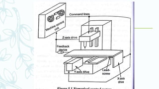
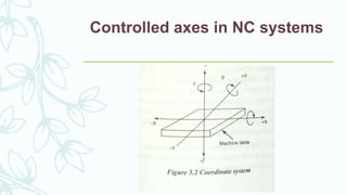
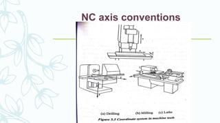
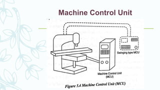
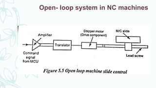
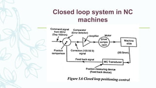
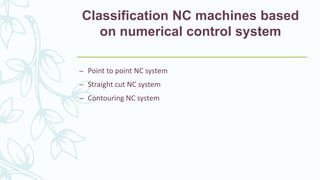
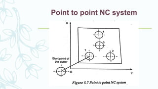
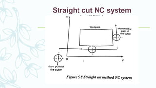
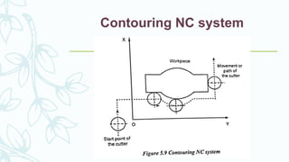
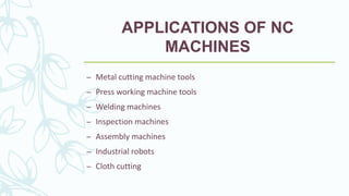
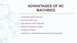
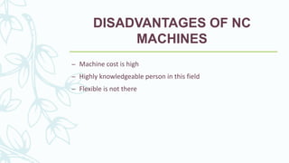
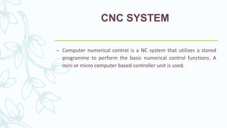
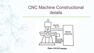
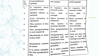
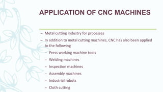
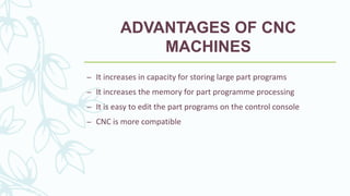
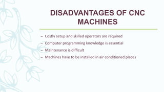
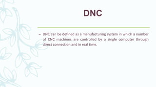
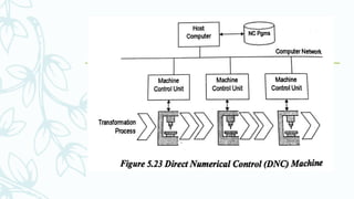
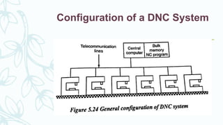
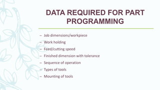
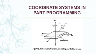
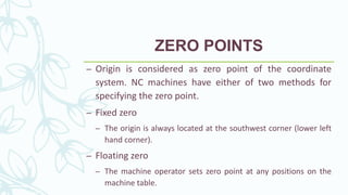
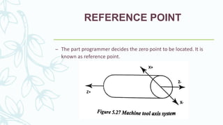
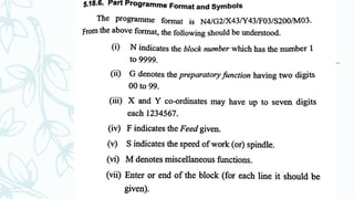
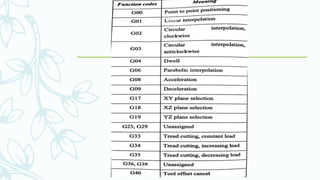
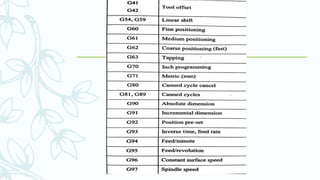
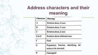
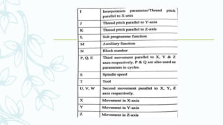
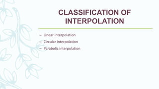
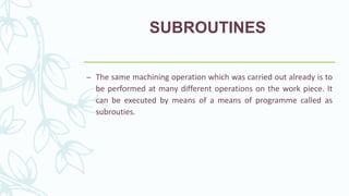
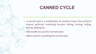
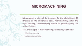
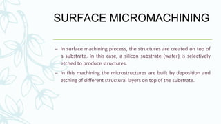
SlideShare a Scribd company logo
1 of 88
NUMERICAL CONTROL SYSTEM
– Numerical control refers to the automation of machine tools
operated by programmed commands encoded on a storage
medium against to manual control through hand wheels or
mechanically automated through cams alone.
– Controlling a machine tool by means of a prepared programme is
known as Numerical Control or NC
Definition of NC System
– A system in which actions are controlled by the direct insertion of
numerical data at some point is known as NC system.
TYPES OF NC SYSTEM
– Traditional numerical control (NC)
– Computer numerical control (CNC)
– Distributed numerical control (DNC)
Controlled axes in NC systems
NC axis conventions
Basic components of NC
– Software
– Machine Control Unit (MCU)
– Machine tool
Machine Control Unit
– Input or reader unit
– Memory
– Processor
– Output channel
– Control panel
– Feed back channel
CLASSIFICATION NC MACHINES
BASED ON CONTROL SYSTEM
– Open- loop system in NC machines
– Closed loop system in NC machines
Open- loop system in NC machines
Closed loop system in NC
machines
Classification NC machines based
on numerical control system
– Point to point NC system
– Straight cut NC system
– Contouring NC system
Point to point NC system
Straight cut NC system
Contouring NC system
Driving system of NC Machines
– Electromechanical devices
– Digital circuits
AC Drives
– Principle of operation
The velocity of AC synchro motor is controlled by
manipulating the voltage frequency supplied by the motor. The
frequency manipulation requires the use of an electrical inverter, the
inverter contains DC power supply and the circuit inverts DC voltage
into AC voltage with a continuously controllable frequency.
DC MOTORS
STEPPING MOTOR
– Principle of operation
The drive unit contains a steering circuit and a power
amplifier. It translates the input pulses into the correct switching
sequence required to step the motor.
HYDRAULIC SYSTEMS
PNEUMATIC DRIVES
TOOLING SYSTEMS IN NC
MACHINES
– Using quick change tool holders
– Automatic tool selection
– Changing tools automatically for sequence of operations
APPLICATIONS OF NC
MACHINES
– Metal cutting machine tools
– Press working machine tools
– Welding machines
– Inspection machines
– Assembly machines
– Industrial robots
– Cloth cutting
ADVANTAGES OF NC
MACHINES
– It provides greater accuracy
– Less production cost
– Less operator skill is required
– Machine utilization is better
– Tooling cost is less
– Cycle time is reduced thereby increasing the tool life.
DISADVANTAGES OF NC
MACHINES
– Machine cost is high
– Highly knowledgeable person in this field
– Flexible is not there
CNC SYSTEM
– Computer numerical control is a NC system that utilizes a stored
programme to perform the basic numerical control functions. A
mini or micro computer based controller unit is used.
The type of CNC used in these
above- said fields are given below
– CNC lathes
– CNC turning centres
– Gear hobbing machines
– Gear shaping machines
– Tube bending
– Electron beam welding
– Press brakes
– Abrasive water jet machines
– Coordinate measuring machines
Types of CNC
– Hybrid CNC
– Straight CNC
Major Elements of CNC systems
– Hardware
– Software
– Information
CNC Machine Constructional
details
Special features of CNC
machines
– CNC drive systems
– Feed drive
– Slide movement element
– coolant control
– Working of automatic tool changer
– Work holding system
– CNC controller
– Type of CNC machines
CNC drive systems
– Cutting spindles
– Spindle heads
Working of automatic tool changer
– Drum type
– Chain type
Work holding system
– Collet chuck
– Jaw chuck
– Arbors
– Fixtures
MACHINING CENTRES
The following operations are carried out
– Milling
– Drilling
– Reaming
– Boring
– Tapping
Classification of machining centres
– Horizontal spindle machining centres
– Vertical spindle machining centre
– Universal machining centre
Horizontal spindle machining
centres
Vertical spindle machining centre
TURNING CENTRES
– Horizontal machines
– Vertical machines
CLASSIFICATION OF
HORIZONTAL MACHINES
– Chucking machines
– Shaft machines
– Universal machines
Chucking machines
CNC ELECTRICAL DISCHARGE
MACHINING
– RAM type EDM CNC machine
– Orbital type EDM CNC machine
– Wire cut EDM CNC machine
DESIGN CONSIDERATIONS OF
CNC MACHINES
– Static load
– Dynamic load
– Thermal load
– Guideways
– Measuring system
– Tool monitoring system
APPLICATION OF CNC MACHINES
– Metal cutting industry for processes
– In addition to metal cutting machines, CNC has also been applied
to the following
– Press working machine tools
– Welding machines
– Inspection machines
– Assembly machines
– Industrial robots
– Cloth cutting
ADVANTAGES OF CNC
MACHINES
– It increases in capacity for storing large part programs
– It increases the memory for part programme processing
– It is easy to edit the part programs on the control console
– CNC is more compatible
DISADVANTAGES OF CNC
MACHINES
– Costly setup and skilled operators are required
– Computer programming knowledge is essential
– Maintenance is difficult
– Machines have to be installed in air conditioned places
DNC
– DNC can be defined as a manufacturing system in which a number
of CNC machines are controlled by a single computer through
direct connection and in real time.
Configuration of a DNC System
ADVANTAGES OF DNC
– The computer can be remotely located even a thousand miles
away
– The computer can simultaneously programme for many NC
machines
PART PROGRAMMING
FUNDAMENTALS
– The conversion of engineering blueprint to a part
programme can manually be performed or with the
assistance of a high level computer language.
– Part program
– Methods of creating part programming
Part program
– The part programme is a set of instructions proposed to get the
machined part starting with the desired blank and NC machine
tool.
Methods of creating part
programming
– Manual part programming
– Computer assisted part programming (CAD/CAM)
– Manual data input
– Computer automated part programming
CNC MANUAL PART
PROGRAMMING
– To prepare a part programme using a manual method, the
programmer writes the machining instructions on a special format
called part programming manuscript.
– The manual programming jobs can be divided into two categories
– Point to point jobs
– Contouring jobs
DATA REQUIRED FOR PART
PROGRAMMING
– Job dimensions/workpiece
– Work holding
– Feed/cutting speed
– Finished dimension with tolerance
– Sequence of operation
– Types of tools
– Mounting of tools
COORDINATE SYSTEMS IN
PART PROGRAMMING
ZERO POINTS
– Origin is considered as zero point of the coordinate
system. NC machines have either of two methods for
specifying the zero point.
– Fixed zero
– The origin is always located at the southwest corner (lower left
hand corner).
– Floating zero
– The machine operator sets zero point at any positions on the
machine table.
REFERENCE POINT
– The part programmer decides the zero point to be located. It is
known as reference point.
NC related dimensioning in part
programming
– There are two type of positioning
– Absolute positioning
– The tool locations are always defined in relation to zero point. G90
code is used in a part programme to represent absolute mode
– Incremental positioning
– The next tool location must be defined with reference to the
previous tool location. G91 code is used in a part programme to
represent incremental mode
There are two types of unit system
follows
– Inch system
– G70 command is used
– Metric system
– G71 command is used
The following steps should be kept in
mind while writing the programme
– Fixation of coordinate system
– Reference of G and M codes
– Dimensions of work and tools
– Locating the fixture and machine table
– Speed and feed according to the work and tool material.
PREPARATORY FUNCTIONS (G) IN
PART PROGRAMMING
– Preparatory commands which prepare the machine or
tool for different modes of movement positioning.
MISCELLANEOUS FUNCTION IN
PART PROGRAMMING
– The function not relating the dimensional movement of the
machine but it denotes the auxiliary or switching information is
called miscellaneous functions.
– For example coolant on/off, spindle speed
Address characters and their
meaning
INTERPOLATION IN PART
PROGRAMMING
– It is the process of developing coordinate points in between start
and finish coordinates.
– Interpolation in NC machining is required to calculate the
intermediate points of a curve or straight line when its start and
end coordinates are given. Interpolation may be linear, circular or
cubic/parabolic.
INTERPOLATOR
– External interpolator
– Internal interpolator
CLASSIFICATION OF
INTERPOLATION
– Linear interpolation
– Circular interpolation
– Parabolic interpolation
SUBROUTINES
– The same machining operation which was carried out already is to
be performed at many different operations on the work piece. It
can be executed by means of a means of programme called as
subrouties.
CANNED CYCLE
– A canned cycle is a combination of machine moves that performs
anyone particular machining function drilling, turning, milling,
boring, tapping etc.
– G81 to G89 are used for canned cycles
– G80 is used for cancelling the canned cycle
MICROMACHINING
– Micromachining refers of the technique for the fabrication of 3D
structure on the micrometer scale. Micromachining refers the
super finishing, a metalworking process for producing very fine
surface finishes.
– The various types of micromachining process are given below
– Bulk micromachining
– Surface micromachining
SURFACE MICROMACHINING
– In surface machining process, the structures are created on top of
a substrate. In this case, a silicon substrate (wafer) is selectively
etched to produce structures.
– In this machining the microstructures are built by deposition and
etching of different structural layers on top of the substrate.
WAFER MACHINING
Numerical Controlled System Basic Fundamental

More Related Content

Similar to Numerical Controlled System Basic Fundamental

Similar to Numerical Controlled System Basic Fundamental (20)

9.pmat m 01
9.pmat m 019.pmat m 01
9.pmat m 01
 
Part programming for nc machines
Part programming for nc machinesPart programming for nc machines
Part programming for nc machines
 
CNC Machines and its Components
CNC Machines and its ComponentsCNC Machines and its Components
CNC Machines and its Components
 
cnc machining
cnc machiningcnc machining
cnc machining
 
M.P- II-UNIT V - CNC MACHINE TOOLS AND PART PROGRAMMING.ppt
M.P- II-UNIT V - CNC MACHINE TOOLS AND PART PROGRAMMING.pptM.P- II-UNIT V - CNC MACHINE TOOLS AND PART PROGRAMMING.ppt
M.P- II-UNIT V - CNC MACHINE TOOLS AND PART PROGRAMMING.ppt
 
CNC Milling
CNC MillingCNC Milling
CNC Milling
 
CNC MACHINE TOOLS Introduction Module 1.ppt
CNC MACHINE TOOLS Introduction Module 1.pptCNC MACHINE TOOLS Introduction Module 1.ppt
CNC MACHINE TOOLS Introduction Module 1.ppt
 
Modern machine
Modern machineModern machine
Modern machine
 
Computer numerical control ( CNC )
Computer numerical control  ( CNC )Computer numerical control  ( CNC )
Computer numerical control ( CNC )
 
12 cnc & part programming
12 cnc & part programming12 cnc & part programming
12 cnc & part programming
 
INTRODUCTION ABOUT CNC MACHINE with G Code and M Code.pptx
INTRODUCTION ABOUT CNC MACHINE with G Code and M Code.pptxINTRODUCTION ABOUT CNC MACHINE with G Code and M Code.pptx
INTRODUCTION ABOUT CNC MACHINE with G Code and M Code.pptx
 
cncseminar-121020053500-phpapp01-170219102752 (1).pdf
cncseminar-121020053500-phpapp01-170219102752 (1).pdfcncseminar-121020053500-phpapp01-170219102752 (1).pdf
cncseminar-121020053500-phpapp01-170219102752 (1).pdf
 
ppt on cnc
ppt on cncppt on cnc
ppt on cnc
 
LEARN CNC.pptx
LEARN CNC.pptxLEARN CNC.pptx
LEARN CNC.pptx
 
COMPUTER NUMERIC CONTROL
COMPUTER NUMERIC CONTROL COMPUTER NUMERIC CONTROL
COMPUTER NUMERIC CONTROL
 
Computer Aided Manufacturing.pptx
Computer Aided Manufacturing.pptxComputer Aided Manufacturing.pptx
Computer Aided Manufacturing.pptx
 
geometric modelling and PLC
geometric modelling and PLCgeometric modelling and PLC
geometric modelling and PLC
 
cnc
cnccnc
cnc
 
CNC MACHINE TOOLS.ppt
CNC MACHINE TOOLS.pptCNC MACHINE TOOLS.ppt
CNC MACHINE TOOLS.ppt
 
MT-II UNIT V CNC MACHINING
MT-II UNIT V CNC MACHININGMT-II UNIT V CNC MACHINING
MT-II UNIT V CNC MACHINING
 

Recently uploaded

RESORT MANAGEMENT AND RESERVATION SYSTEM PROJECT REPORT.pdf
RESORT MANAGEMENT AND RESERVATION SYSTEM PROJECT REPORT.pdfRESORT MANAGEMENT AND RESERVATION SYSTEM PROJECT REPORT.pdf
RESORT MANAGEMENT AND RESERVATION SYSTEM PROJECT REPORT.pdfKamal Acharya
 
DR PROF ING GURUDUTT SAHNI WIKIPEDIA.pdf
DR PROF ING GURUDUTT SAHNI WIKIPEDIA.pdfDR PROF ING GURUDUTT SAHNI WIKIPEDIA.pdf
DR PROF ING GURUDUTT SAHNI WIKIPEDIA.pdfDrGurudutt
 
Furniture showroom management system project.pdf
Furniture showroom management system project.pdfFurniture showroom management system project.pdf
Furniture showroom management system project.pdfKamal Acharya
 
An improvement in the safety of big data using blockchain technology
An improvement in the safety of big data using blockchain technologyAn improvement in the safety of big data using blockchain technology
An improvement in the safety of big data using blockchain technologyBOHRInternationalJou1
 
retail automation billing system ppt.pptx
retail automation billing system ppt.pptxretail automation billing system ppt.pptx
retail automation billing system ppt.pptxfaamieahmd
 
Paint shop management system project report.pdf
Paint shop management system project report.pdfPaint shop management system project report.pdf
Paint shop management system project report.pdfKamal Acharya
 
Research Methodolgy & Intellectual Property Rights Series 2
Research Methodolgy & Intellectual Property Rights Series 2Research Methodolgy & Intellectual Property Rights Series 2
Research Methodolgy & Intellectual Property Rights Series 2T.D. Shashikala
 
Laundry management system project report.pdf
Laundry management system project report.pdfLaundry management system project report.pdf
Laundry management system project report.pdfKamal Acharya
 
Construction method of steel structure space frame .pptx
Construction method of steel structure space frame .pptxConstruction method of steel structure space frame .pptx
Construction method of steel structure space frame .pptxwendy cai
 
ONLINE VEHICLE RENTAL SYSTEM PROJECT REPORT.pdf
ONLINE VEHICLE RENTAL SYSTEM PROJECT REPORT.pdfONLINE VEHICLE RENTAL SYSTEM PROJECT REPORT.pdf
ONLINE VEHICLE RENTAL SYSTEM PROJECT REPORT.pdfKamal Acharya
 
ENERGY STORAGE DEVICES INTRODUCTION UNIT-I
ENERGY STORAGE DEVICES  INTRODUCTION UNIT-IENERGY STORAGE DEVICES  INTRODUCTION UNIT-I
ENERGY STORAGE DEVICES INTRODUCTION UNIT-IVigneshvaranMech
 
Online book store management system project.pdf
Online book store management system project.pdfOnline book store management system project.pdf
Online book store management system project.pdfKamal Acharya
 
Arduino based vehicle speed tracker project
Arduino based vehicle speed tracker projectArduino based vehicle speed tracker project
Arduino based vehicle speed tracker projectRased Khan
 
RM&IPR M5 notes.pdfResearch Methodolgy & Intellectual Property Rights Series 5
RM&IPR M5 notes.pdfResearch Methodolgy & Intellectual Property Rights Series 5RM&IPR M5 notes.pdfResearch Methodolgy & Intellectual Property Rights Series 5
RM&IPR M5 notes.pdfResearch Methodolgy & Intellectual Property Rights Series 5T.D. Shashikala
 
The battle for RAG, explore the pros and cons of using KnowledgeGraphs and Ve...
The battle for RAG, explore the pros and cons of using KnowledgeGraphs and Ve...The battle for RAG, explore the pros and cons of using KnowledgeGraphs and Ve...
The battle for RAG, explore the pros and cons of using KnowledgeGraphs and Ve...Roi Lipman
 
Online resume builder management system project report.pdf
Online resume builder management system project report.pdfOnline resume builder management system project report.pdf
Online resume builder management system project report.pdfKamal Acharya
 
İTÜ CAD and Reverse Engineering Workshop
İTÜ CAD and Reverse Engineering WorkshopİTÜ CAD and Reverse Engineering Workshop
İTÜ CAD and Reverse Engineering WorkshopEmre Günaydın
 
BRAKING SYSTEM IN INDIAN RAILWAY AutoCAD DRAWING
BRAKING SYSTEM IN INDIAN RAILWAY AutoCAD DRAWINGBRAKING SYSTEM IN INDIAN RAILWAY AutoCAD DRAWING
BRAKING SYSTEM IN INDIAN RAILWAY AutoCAD DRAWINGKOUSTAV SARKAR
 
KIT-601 Lecture Notes-UNIT-4.pdf Frequent Itemsets and Clustering
KIT-601 Lecture Notes-UNIT-4.pdf Frequent Itemsets and ClusteringKIT-601 Lecture Notes-UNIT-4.pdf Frequent Itemsets and Clustering
KIT-601 Lecture Notes-UNIT-4.pdf Frequent Itemsets and ClusteringDr. Radhey Shyam
 
Digital Signal Processing Lecture notes n.pdf
Digital Signal Processing Lecture notes n.pdfDigital Signal Processing Lecture notes n.pdf
Digital Signal Processing Lecture notes n.pdfAbrahamGadissa
 

Recently uploaded (20)

RESORT MANAGEMENT AND RESERVATION SYSTEM PROJECT REPORT.pdf
RESORT MANAGEMENT AND RESERVATION SYSTEM PROJECT REPORT.pdfRESORT MANAGEMENT AND RESERVATION SYSTEM PROJECT REPORT.pdf
RESORT MANAGEMENT AND RESERVATION SYSTEM PROJECT REPORT.pdf
 
DR PROF ING GURUDUTT SAHNI WIKIPEDIA.pdf
DR PROF ING GURUDUTT SAHNI WIKIPEDIA.pdfDR PROF ING GURUDUTT SAHNI WIKIPEDIA.pdf
DR PROF ING GURUDUTT SAHNI WIKIPEDIA.pdf
 
Furniture showroom management system project.pdf
Furniture showroom management system project.pdfFurniture showroom management system project.pdf
Furniture showroom management system project.pdf
 
An improvement in the safety of big data using blockchain technology
An improvement in the safety of big data using blockchain technologyAn improvement in the safety of big data using blockchain technology
An improvement in the safety of big data using blockchain technology
 
retail automation billing system ppt.pptx
retail automation billing system ppt.pptxretail automation billing system ppt.pptx
retail automation billing system ppt.pptx
 
Paint shop management system project report.pdf
Paint shop management system project report.pdfPaint shop management system project report.pdf
Paint shop management system project report.pdf
 
Research Methodolgy & Intellectual Property Rights Series 2
Research Methodolgy & Intellectual Property Rights Series 2Research Methodolgy & Intellectual Property Rights Series 2
Research Methodolgy & Intellectual Property Rights Series 2
 
Laundry management system project report.pdf
Laundry management system project report.pdfLaundry management system project report.pdf
Laundry management system project report.pdf
 
Construction method of steel structure space frame .pptx
Construction method of steel structure space frame .pptxConstruction method of steel structure space frame .pptx
Construction method of steel structure space frame .pptx
 
ONLINE VEHICLE RENTAL SYSTEM PROJECT REPORT.pdf
ONLINE VEHICLE RENTAL SYSTEM PROJECT REPORT.pdfONLINE VEHICLE RENTAL SYSTEM PROJECT REPORT.pdf
ONLINE VEHICLE RENTAL SYSTEM PROJECT REPORT.pdf
 
ENERGY STORAGE DEVICES INTRODUCTION UNIT-I
ENERGY STORAGE DEVICES  INTRODUCTION UNIT-IENERGY STORAGE DEVICES  INTRODUCTION UNIT-I
ENERGY STORAGE DEVICES INTRODUCTION UNIT-I
 
Online book store management system project.pdf
Online book store management system project.pdfOnline book store management system project.pdf
Online book store management system project.pdf
 
Arduino based vehicle speed tracker project
Arduino based vehicle speed tracker projectArduino based vehicle speed tracker project
Arduino based vehicle speed tracker project
 
RM&IPR M5 notes.pdfResearch Methodolgy & Intellectual Property Rights Series 5
RM&IPR M5 notes.pdfResearch Methodolgy & Intellectual Property Rights Series 5RM&IPR M5 notes.pdfResearch Methodolgy & Intellectual Property Rights Series 5
RM&IPR M5 notes.pdfResearch Methodolgy & Intellectual Property Rights Series 5
 
The battle for RAG, explore the pros and cons of using KnowledgeGraphs and Ve...
The battle for RAG, explore the pros and cons of using KnowledgeGraphs and Ve...The battle for RAG, explore the pros and cons of using KnowledgeGraphs and Ve...
The battle for RAG, explore the pros and cons of using KnowledgeGraphs and Ve...
 
Online resume builder management system project report.pdf
Online resume builder management system project report.pdfOnline resume builder management system project report.pdf
Online resume builder management system project report.pdf
 
İTÜ CAD and Reverse Engineering Workshop
İTÜ CAD and Reverse Engineering WorkshopİTÜ CAD and Reverse Engineering Workshop
İTÜ CAD and Reverse Engineering Workshop
 
BRAKING SYSTEM IN INDIAN RAILWAY AutoCAD DRAWING
BRAKING SYSTEM IN INDIAN RAILWAY AutoCAD DRAWINGBRAKING SYSTEM IN INDIAN RAILWAY AutoCAD DRAWING
BRAKING SYSTEM IN INDIAN RAILWAY AutoCAD DRAWING
 
KIT-601 Lecture Notes-UNIT-4.pdf Frequent Itemsets and Clustering
KIT-601 Lecture Notes-UNIT-4.pdf Frequent Itemsets and ClusteringKIT-601 Lecture Notes-UNIT-4.pdf Frequent Itemsets and Clustering
KIT-601 Lecture Notes-UNIT-4.pdf Frequent Itemsets and Clustering
 
Digital Signal Processing Lecture notes n.pdf
Digital Signal Processing Lecture notes n.pdfDigital Signal Processing Lecture notes n.pdf
Digital Signal Processing Lecture notes n.pdf
 

Numerical Controlled System Basic Fundamental

  • 1. NUMERICAL CONTROL SYSTEM – Numerical control refers to the automation of machine tools operated by programmed commands encoded on a storage medium against to manual control through hand wheels or mechanically automated through cams alone. – Controlling a machine tool by means of a prepared programme is known as Numerical Control or NC
  • 2. Definition of NC System – A system in which actions are controlled by the direct insertion of numerical data at some point is known as NC system.
  • 3.
  • 4. TYPES OF NC SYSTEM – Traditional numerical control (NC) – Computer numerical control (CNC) – Distributed numerical control (DNC)
  • 5. Controlled axes in NC systems
  • 7. Basic components of NC – Software – Machine Control Unit (MCU) – Machine tool
  • 9. – Input or reader unit – Memory – Processor – Output channel – Control panel – Feed back channel
  • 10. CLASSIFICATION NC MACHINES BASED ON CONTROL SYSTEM – Open- loop system in NC machines – Closed loop system in NC machines
  • 11. Open- loop system in NC machines
  • 12. Closed loop system in NC machines
  • 13. Classification NC machines based on numerical control system – Point to point NC system – Straight cut NC system – Contouring NC system
  • 14. Point to point NC system
  • 15. Straight cut NC system
  • 17. Driving system of NC Machines – Electromechanical devices – Digital circuits
  • 18. AC Drives – Principle of operation The velocity of AC synchro motor is controlled by manipulating the voltage frequency supplied by the motor. The frequency manipulation requires the use of an electrical inverter, the inverter contains DC power supply and the circuit inverts DC voltage into AC voltage with a continuously controllable frequency.
  • 20. STEPPING MOTOR – Principle of operation The drive unit contains a steering circuit and a power amplifier. It translates the input pulses into the correct switching sequence required to step the motor.
  • 23. TOOLING SYSTEMS IN NC MACHINES – Using quick change tool holders – Automatic tool selection – Changing tools automatically for sequence of operations
  • 24. APPLICATIONS OF NC MACHINES – Metal cutting machine tools – Press working machine tools – Welding machines – Inspection machines – Assembly machines – Industrial robots – Cloth cutting
  • 25. ADVANTAGES OF NC MACHINES – It provides greater accuracy – Less production cost – Less operator skill is required – Machine utilization is better – Tooling cost is less – Cycle time is reduced thereby increasing the tool life.
  • 26. DISADVANTAGES OF NC MACHINES – Machine cost is high – Highly knowledgeable person in this field – Flexible is not there
  • 27. CNC SYSTEM – Computer numerical control is a NC system that utilizes a stored programme to perform the basic numerical control functions. A mini or micro computer based controller unit is used.
  • 28.
  • 29. The type of CNC used in these above- said fields are given below – CNC lathes – CNC turning centres – Gear hobbing machines – Gear shaping machines – Tube bending – Electron beam welding – Press brakes – Abrasive water jet machines – Coordinate measuring machines
  • 30. Types of CNC – Hybrid CNC – Straight CNC
  • 31. Major Elements of CNC systems – Hardware – Software – Information
  • 33. Special features of CNC machines – CNC drive systems – Feed drive – Slide movement element – coolant control – Working of automatic tool changer – Work holding system – CNC controller – Type of CNC machines
  • 34. CNC drive systems – Cutting spindles – Spindle heads
  • 35.
  • 36. Working of automatic tool changer – Drum type – Chain type
  • 37. Work holding system – Collet chuck – Jaw chuck – Arbors – Fixtures
  • 38. MACHINING CENTRES The following operations are carried out – Milling – Drilling – Reaming – Boring – Tapping
  • 39. Classification of machining centres – Horizontal spindle machining centres – Vertical spindle machining centre – Universal machining centre
  • 42. TURNING CENTRES – Horizontal machines – Vertical machines
  • 43. CLASSIFICATION OF HORIZONTAL MACHINES – Chucking machines – Shaft machines – Universal machines
  • 45. CNC ELECTRICAL DISCHARGE MACHINING – RAM type EDM CNC machine – Orbital type EDM CNC machine – Wire cut EDM CNC machine
  • 46. DESIGN CONSIDERATIONS OF CNC MACHINES – Static load – Dynamic load – Thermal load – Guideways – Measuring system – Tool monitoring system
  • 47.
  • 48. APPLICATION OF CNC MACHINES – Metal cutting industry for processes – In addition to metal cutting machines, CNC has also been applied to the following – Press working machine tools – Welding machines – Inspection machines – Assembly machines – Industrial robots – Cloth cutting
  • 49. ADVANTAGES OF CNC MACHINES – It increases in capacity for storing large part programs – It increases the memory for part programme processing – It is easy to edit the part programs on the control console – CNC is more compatible
  • 50. DISADVANTAGES OF CNC MACHINES – Costly setup and skilled operators are required – Computer programming knowledge is essential – Maintenance is difficult – Machines have to be installed in air conditioned places
  • 51. DNC – DNC can be defined as a manufacturing system in which a number of CNC machines are controlled by a single computer through direct connection and in real time.
  • 52.
  • 53. Configuration of a DNC System
  • 54. ADVANTAGES OF DNC – The computer can be remotely located even a thousand miles away – The computer can simultaneously programme for many NC machines
  • 55. PART PROGRAMMING FUNDAMENTALS – The conversion of engineering blueprint to a part programme can manually be performed or with the assistance of a high level computer language. – Part program – Methods of creating part programming
  • 56. Part program – The part programme is a set of instructions proposed to get the machined part starting with the desired blank and NC machine tool.
  • 57.
  • 58. Methods of creating part programming – Manual part programming – Computer assisted part programming (CAD/CAM) – Manual data input – Computer automated part programming
  • 59. CNC MANUAL PART PROGRAMMING – To prepare a part programme using a manual method, the programmer writes the machining instructions on a special format called part programming manuscript. – The manual programming jobs can be divided into two categories – Point to point jobs – Contouring jobs
  • 60. DATA REQUIRED FOR PART PROGRAMMING – Job dimensions/workpiece – Work holding – Feed/cutting speed – Finished dimension with tolerance – Sequence of operation – Types of tools – Mounting of tools
  • 62. ZERO POINTS – Origin is considered as zero point of the coordinate system. NC machines have either of two methods for specifying the zero point. – Fixed zero – The origin is always located at the southwest corner (lower left hand corner). – Floating zero – The machine operator sets zero point at any positions on the machine table.
  • 63. REFERENCE POINT – The part programmer decides the zero point to be located. It is known as reference point.
  • 64. NC related dimensioning in part programming – There are two type of positioning – Absolute positioning – The tool locations are always defined in relation to zero point. G90 code is used in a part programme to represent absolute mode – Incremental positioning – The next tool location must be defined with reference to the previous tool location. G91 code is used in a part programme to represent incremental mode
  • 65.
  • 66. There are two types of unit system follows – Inch system – G70 command is used – Metric system – G71 command is used
  • 67. The following steps should be kept in mind while writing the programme – Fixation of coordinate system – Reference of G and M codes – Dimensions of work and tools – Locating the fixture and machine table – Speed and feed according to the work and tool material.
  • 68.
  • 69. PREPARATORY FUNCTIONS (G) IN PART PROGRAMMING – Preparatory commands which prepare the machine or tool for different modes of movement positioning.
  • 70.
  • 71.
  • 72. MISCELLANEOUS FUNCTION IN PART PROGRAMMING – The function not relating the dimensional movement of the machine but it denotes the auxiliary or switching information is called miscellaneous functions. – For example coolant on/off, spindle speed
  • 73.
  • 74.
  • 75.
  • 76.
  • 77. Address characters and their meaning
  • 78.
  • 79. INTERPOLATION IN PART PROGRAMMING – It is the process of developing coordinate points in between start and finish coordinates. – Interpolation in NC machining is required to calculate the intermediate points of a curve or straight line when its start and end coordinates are given. Interpolation may be linear, circular or cubic/parabolic.
  • 81. CLASSIFICATION OF INTERPOLATION – Linear interpolation – Circular interpolation – Parabolic interpolation
  • 82. SUBROUTINES – The same machining operation which was carried out already is to be performed at many different operations on the work piece. It can be executed by means of a means of programme called as subrouties.
  • 83. CANNED CYCLE – A canned cycle is a combination of machine moves that performs anyone particular machining function drilling, turning, milling, boring, tapping etc. – G81 to G89 are used for canned cycles – G80 is used for cancelling the canned cycle
  • 84. MICROMACHINING – Micromachining refers of the technique for the fabrication of 3D structure on the micrometer scale. Micromachining refers the super finishing, a metalworking process for producing very fine surface finishes. – The various types of micromachining process are given below – Bulk micromachining – Surface micromachining
  • 85.
  • 86. SURFACE MICROMACHINING – In surface machining process, the structures are created on top of a substrate. In this case, a silicon substrate (wafer) is selectively etched to produce structures. – In this machining the microstructures are built by deposition and etching of different structural layers on top of the substrate.