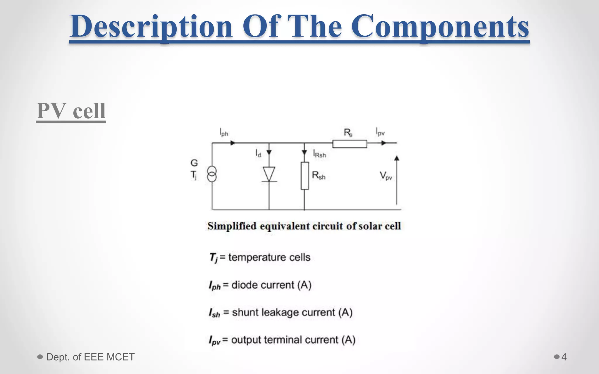
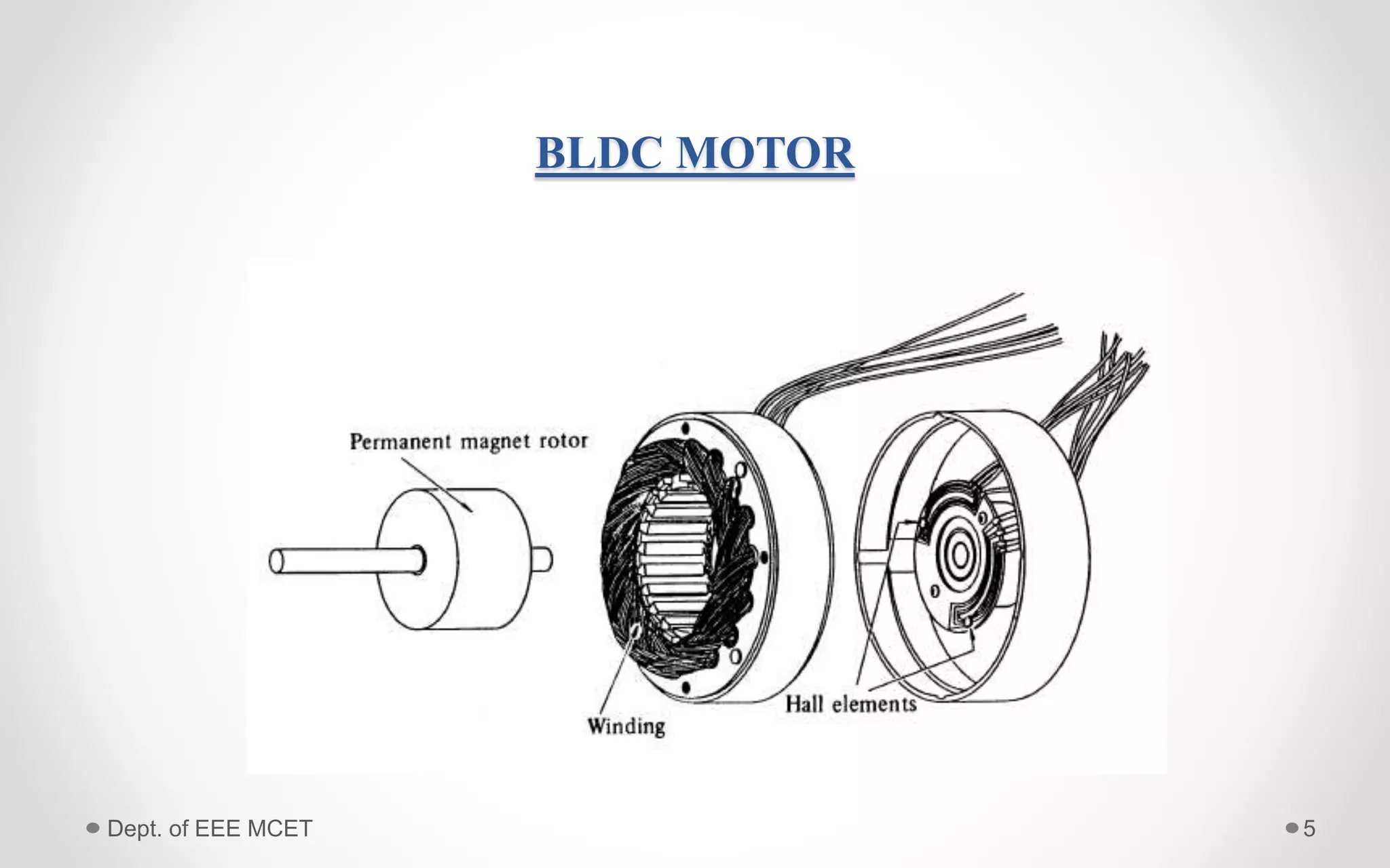
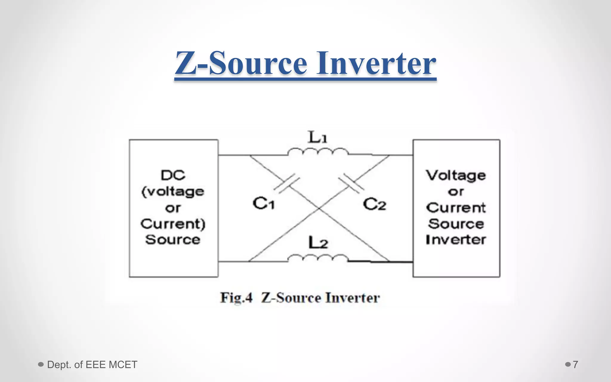
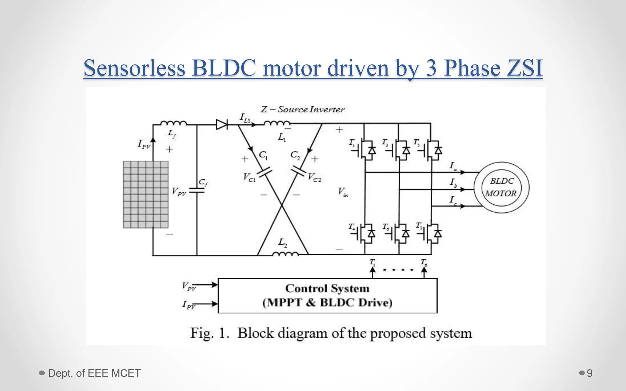
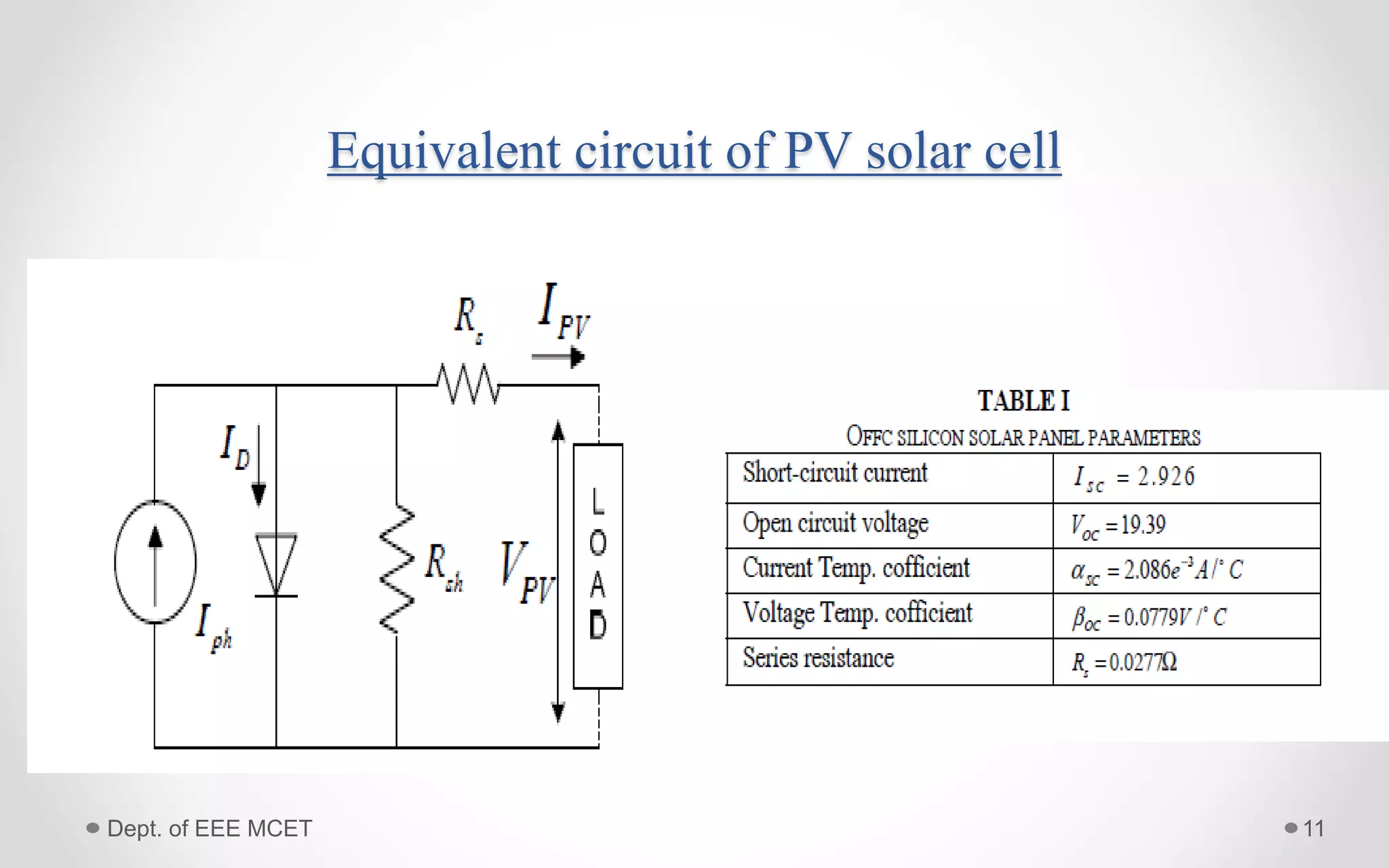
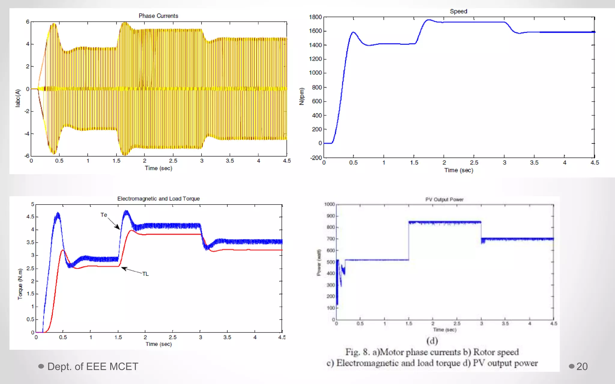
PV Power System Based MPPT Z-
Source Inverter to Supply a
Sensorless BLDC Motor
Guide, Submitted by,
Mr. Manu N Govind Renjith Chandran Nair
Asst: Prof Dept of EEE S7 EEE,
MCET PTA Roll No:4431
1Dept. of EEE MCET
• The solar energy as PV power systems can be operated as a stand-
alone, hybrid or grid connected systems.
• Photovoltaic (PV) water pumping systems have been increasingly
popular in remote areas where grid is not accessible or is too costly
to install.
• PV pumps are already in use in several parts of the world. But they
suffer from maintenance problems due to brushes and commutator .
• The problems can be overcome by choosing BLDC motor.
Introduction
2Dept. of EEE MCET
CONTENTS
• Photovoltaic System
• Conventional PV water pumping system
• Maximum Power Point Tracking(MPPT)
• ZSI
• BLDC motor
3Dept. of EEE MCET
Description Of The Components
PV cell
4Dept. of EEE MCET
BLDC MOTOR
Dept. of EEE MCET 5
Dept. of EEE MCET 6
• A BLDC motor is a rotating electric machine where the stator
is a classic three phase stator like that of an induction motor
and the rotor has surface mounted permanent magnets.
• Also called brushless Permanent Magnet DC (BLDC) or
synchronous DC motor
• The construction of modern brushless motors is very similar to
the ac motor, known as the permanent magnet synchronous
motor.
Z-Source Inverter
7Dept. of EEE MCET
• Z-source inverter (ZSI), which is based on Z-source
network .It can be used to buck and boost the output AC
voltage, which is not possible using traditional voltage
source or current source inverters.
• Figure shows a topology of the single phase Z-source
inverter.
• The impedance network is placed between the power
source and the single phase inverter.
Dept. of EEE MCET 8
Sensorless BLDC motor driven by 3 Phase ZSI
9Dept. of EEE MCET
• The maximum power of PV array is extracted by MPPT
control method and then is fed to the sensor less BLDC motor.
• PV power varies to different environment conditions.
• The sensor less BLDC motor should be driven by variable
reference speed. In order to achieve the reference speed for
sensor less BLDC motor, the input voltage of inverter is
regulated at a constant value (Vinref=300V).
10Dept. of EEE MCET
Equivalent circuit of PV solar cell
11Dept. of EEE MCET
• Figure illustrate the nonlinear variations of the PV maximum
power point respect to irradiation levels.
• The voltage and current of a PV array vary in respect to
insolation and temperature levels, the equation has been
computed for several insolation levels
• In this paper PV system is modelled in the PSCAD program as
a DC voltage source based on equation.
12Dept. of EEE MCET
Output Characteristics of PV module
13Dept. of EEE MCET
BLDC MOTOR DRIVE
• Permanent magnet DC motors use mechanical commutator and
brushes to achieve the commutation.
• It has rotor and stator
• BLDC motors use permanent magnets instead of coils in the
armature and so do not need brushes.
• It has hall effect sensors.
• Sensor detects the rotor position by incremental encoder then it
is removed.
14Dept. of EEE MCET
Back EMF pattern
and reference current
generation
• va, vb, vc- phase
voltages.
• ia, ib, ic-phase currents.
• ea, eb, ec-phase back
EMF waveforms.
• R-phase resistance.
• L-self inductance of
each phase.
• M-mutual inductance
between any two phases
15Dept. of EEE MCET
• VC1 and VC2-capacitors
voltages
• B is the boost factor of ZSI.
• Vd and VO- input and
output
• voltages of impedance
network.
OPERATION PRINCIPLES
16Dept. of EEE MCET
CONTROL SYSTEM DESCRIPTION
17Dept. of EEE MCET
• Fig. describes the basic building blocks of PV array MPPT
control and the sensorless BLDC motor drive.
• The drive system consists of the PI speed controller, reference
current generator, hysteresis current controller, three-phase
ZSI and the motor-load unit.
• First the reference voltage of PV array is determined by the IC
MPPT controller and compared with the PV array voltage.
• The motor currents are compared with the reference currents
and the hysteresis current controller regulates the winding
currents (ia, ib, ic) within the small band around the reference
currents. These switching commands and the Z-Source
switching commands are ORed to drive inverter switches.
18Dept. of EEE MCET
SIMULATION RESULTS
• The proposed system was simulated by PSCAD/EMTDC to
evaluate the system capability in response to different
operation conditions.
• It has three different operating conditions.
19Dept. of EEE MCET
20Dept. of EEE MCET
ADVANTAGES
• Less power switches.
• Smaller capacitance.
• Smaller inductance.
• Fast dynamic response
21Dept. of EEE MCET
CONCLUSION
• This paper proposes a sensor less BLDC motor supplied by PV
array based on ZSI.
• Conventional PV systems needing two stages of power
converters the proposed system has employed just a three
phase ZSI extracting the maximum power of PV array and
driving a sensor less BLDC motor simultaneously for different
operation conditions.
• Less power losses, rapid tracking of MPPT and low
electromagnetic torque ripple, demonstrating high current
control capability.
22Dept. of EEE MCET
REFERENCES
1. M. G. Jabori, “A contribution to the simulation and design
optimization of photovoltaic systems,” IEEE Trans. on EC, vol.
6, no.3, 1991, pp. 401-406.
2. J. Samin and et al, “optimal sizing of Photovoltaic Systems in
Varied Climates,” Elsevier , Solar Energy, vol. 6, No. 2, 1997,
pp.97-107.
3. Z. Zinge, “Optimum Operation of a Combined System of a
Solar Cell Array and a DC Motor,” IEEE Trans. on PAS, vol.
pas-100, no. 3, 1981,pp. 1193-1197.
4. F. Z. Peng, ‘‘Z-source inverter,’’ IEEE Trans. Ind. Appl., vol. 39,
no. 2,pp.504-510, Mar.-April. 2003.
23Dept. of EEE MCET

Pv power system based mppt z source inverter to supply bldc motor

  • 1.
    PV Power SystemBased MPPT Z- Source Inverter to Supply a Sensorless BLDC Motor Guide, Submitted by, Mr. Manu N Govind Renjith Chandran Nair Asst: Prof Dept of EEE S7 EEE, MCET PTA Roll No:4431 1Dept. of EEE MCET
  • 2.
    • The solarenergy as PV power systems can be operated as a stand- alone, hybrid or grid connected systems. • Photovoltaic (PV) water pumping systems have been increasingly popular in remote areas where grid is not accessible or is too costly to install. • PV pumps are already in use in several parts of the world. But they suffer from maintenance problems due to brushes and commutator . • The problems can be overcome by choosing BLDC motor. Introduction 2Dept. of EEE MCET
  • 3.
    CONTENTS • Photovoltaic System •Conventional PV water pumping system • Maximum Power Point Tracking(MPPT) • ZSI • BLDC motor 3Dept. of EEE MCET
  • 4.
    Description Of TheComponents PV cell 4Dept. of EEE MCET
  • 5.
  • 6.
    Dept. of EEEMCET 6 • A BLDC motor is a rotating electric machine where the stator is a classic three phase stator like that of an induction motor and the rotor has surface mounted permanent magnets. • Also called brushless Permanent Magnet DC (BLDC) or synchronous DC motor • The construction of modern brushless motors is very similar to the ac motor, known as the permanent magnet synchronous motor.
  • 7.
  • 8.
    • Z-source inverter(ZSI), which is based on Z-source network .It can be used to buck and boost the output AC voltage, which is not possible using traditional voltage source or current source inverters. • Figure shows a topology of the single phase Z-source inverter. • The impedance network is placed between the power source and the single phase inverter. Dept. of EEE MCET 8
  • 9.
    Sensorless BLDC motordriven by 3 Phase ZSI 9Dept. of EEE MCET
  • 10.
    • The maximumpower of PV array is extracted by MPPT control method and then is fed to the sensor less BLDC motor. • PV power varies to different environment conditions. • The sensor less BLDC motor should be driven by variable reference speed. In order to achieve the reference speed for sensor less BLDC motor, the input voltage of inverter is regulated at a constant value (Vinref=300V). 10Dept. of EEE MCET
  • 11.
    Equivalent circuit ofPV solar cell 11Dept. of EEE MCET
  • 12.
    • Figure illustratethe nonlinear variations of the PV maximum power point respect to irradiation levels. • The voltage and current of a PV array vary in respect to insolation and temperature levels, the equation has been computed for several insolation levels • In this paper PV system is modelled in the PSCAD program as a DC voltage source based on equation. 12Dept. of EEE MCET
  • 13.
    Output Characteristics ofPV module 13Dept. of EEE MCET
  • 14.
    BLDC MOTOR DRIVE •Permanent magnet DC motors use mechanical commutator and brushes to achieve the commutation. • It has rotor and stator • BLDC motors use permanent magnets instead of coils in the armature and so do not need brushes. • It has hall effect sensors. • Sensor detects the rotor position by incremental encoder then it is removed. 14Dept. of EEE MCET
  • 15.
    Back EMF pattern andreference current generation • va, vb, vc- phase voltages. • ia, ib, ic-phase currents. • ea, eb, ec-phase back EMF waveforms. • R-phase resistance. • L-self inductance of each phase. • M-mutual inductance between any two phases 15Dept. of EEE MCET
  • 16.
    • VC1 andVC2-capacitors voltages • B is the boost factor of ZSI. • Vd and VO- input and output • voltages of impedance network. OPERATION PRINCIPLES 16Dept. of EEE MCET
  • 17.
  • 18.
    • Fig. describesthe basic building blocks of PV array MPPT control and the sensorless BLDC motor drive. • The drive system consists of the PI speed controller, reference current generator, hysteresis current controller, three-phase ZSI and the motor-load unit. • First the reference voltage of PV array is determined by the IC MPPT controller and compared with the PV array voltage. • The motor currents are compared with the reference currents and the hysteresis current controller regulates the winding currents (ia, ib, ic) within the small band around the reference currents. These switching commands and the Z-Source switching commands are ORed to drive inverter switches. 18Dept. of EEE MCET
  • 19.
    SIMULATION RESULTS • Theproposed system was simulated by PSCAD/EMTDC to evaluate the system capability in response to different operation conditions. • It has three different operating conditions. 19Dept. of EEE MCET
  • 20.
  • 21.
    ADVANTAGES • Less powerswitches. • Smaller capacitance. • Smaller inductance. • Fast dynamic response 21Dept. of EEE MCET
  • 22.
    CONCLUSION • This paperproposes a sensor less BLDC motor supplied by PV array based on ZSI. • Conventional PV systems needing two stages of power converters the proposed system has employed just a three phase ZSI extracting the maximum power of PV array and driving a sensor less BLDC motor simultaneously for different operation conditions. • Less power losses, rapid tracking of MPPT and low electromagnetic torque ripple, demonstrating high current control capability. 22Dept. of EEE MCET
  • 23.
    REFERENCES 1. M. G.Jabori, “A contribution to the simulation and design optimization of photovoltaic systems,” IEEE Trans. on EC, vol. 6, no.3, 1991, pp. 401-406. 2. J. Samin and et al, “optimal sizing of Photovoltaic Systems in Varied Climates,” Elsevier , Solar Energy, vol. 6, No. 2, 1997, pp.97-107. 3. Z. Zinge, “Optimum Operation of a Combined System of a Solar Cell Array and a DC Motor,” IEEE Trans. on PAS, vol. pas-100, no. 3, 1981,pp. 1193-1197. 4. F. Z. Peng, ‘‘Z-source inverter,’’ IEEE Trans. Ind. Appl., vol. 39, no. 2,pp.504-510, Mar.-April. 2003. 23Dept. of EEE MCET