Download to read offline

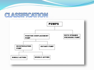


1. The document discusses reciprocating pumps and compressors, describing their construction, working principles, types, and applications. 2. Reciprocating pumps are described as having components like a crank, connecting rod, piston, cylinders, suction and delivery pipes, and sump. Their working involves using the crank to move the piston and create suction and pressure cycles to pump liquid. 3. Reciprocating compressors are also discussed, with descriptions of single-acting and steady flow models. Compressed air has applications in areas like glass furnaces, spraying, and power generation.


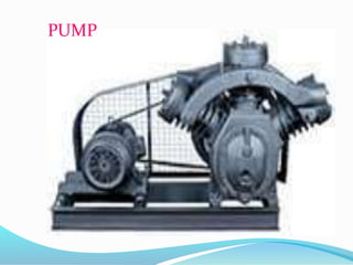
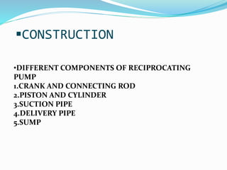
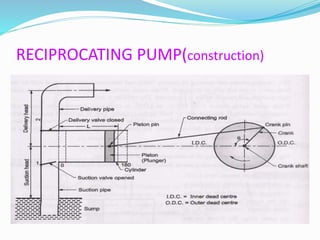
![SBP- Air compressor [Compatibility Mode].pdf](https://cdn.slidesharecdn.com/ss_thumbnails/sbp-aircompressorcompatibilitymode-241227102120-b6a67cde-thumbnail.jpg?width=640&height=640&fit=bounds)


