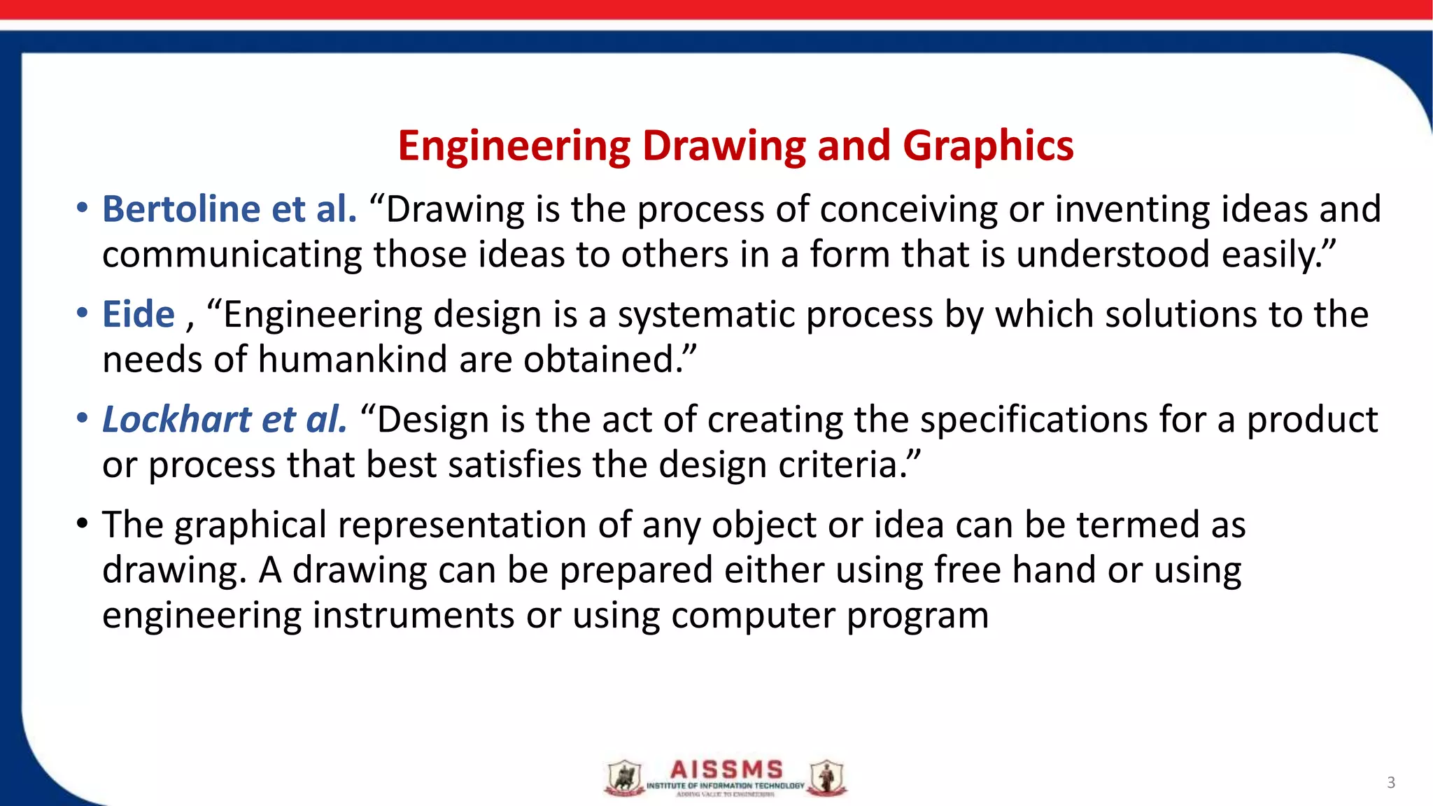
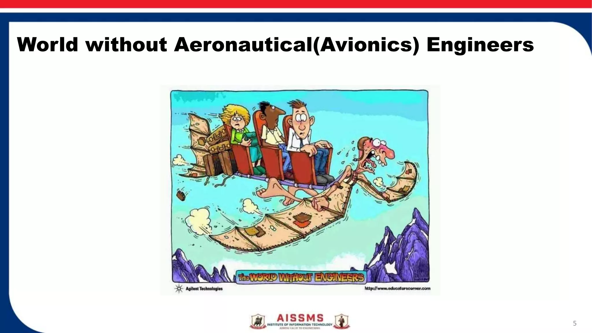
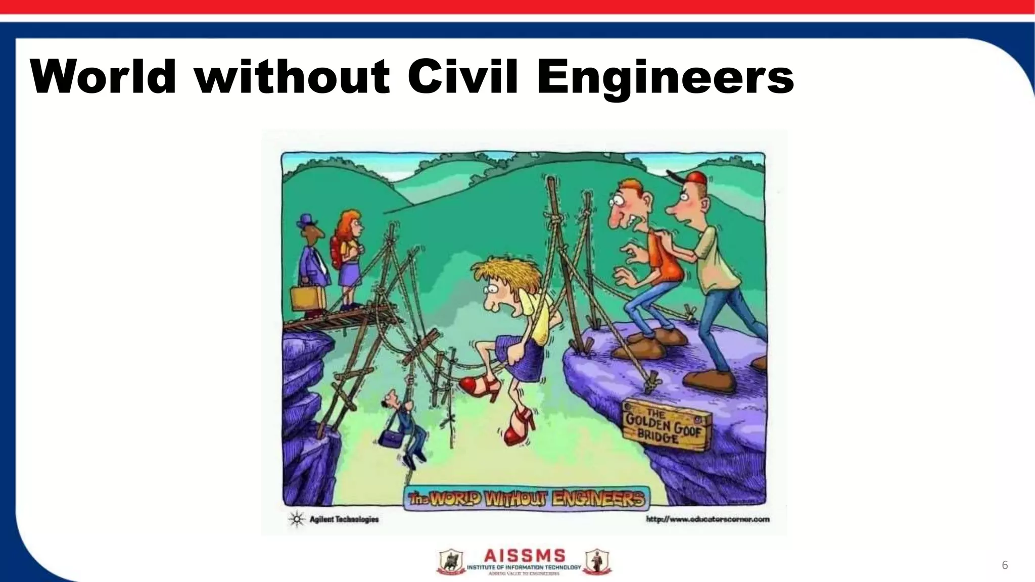
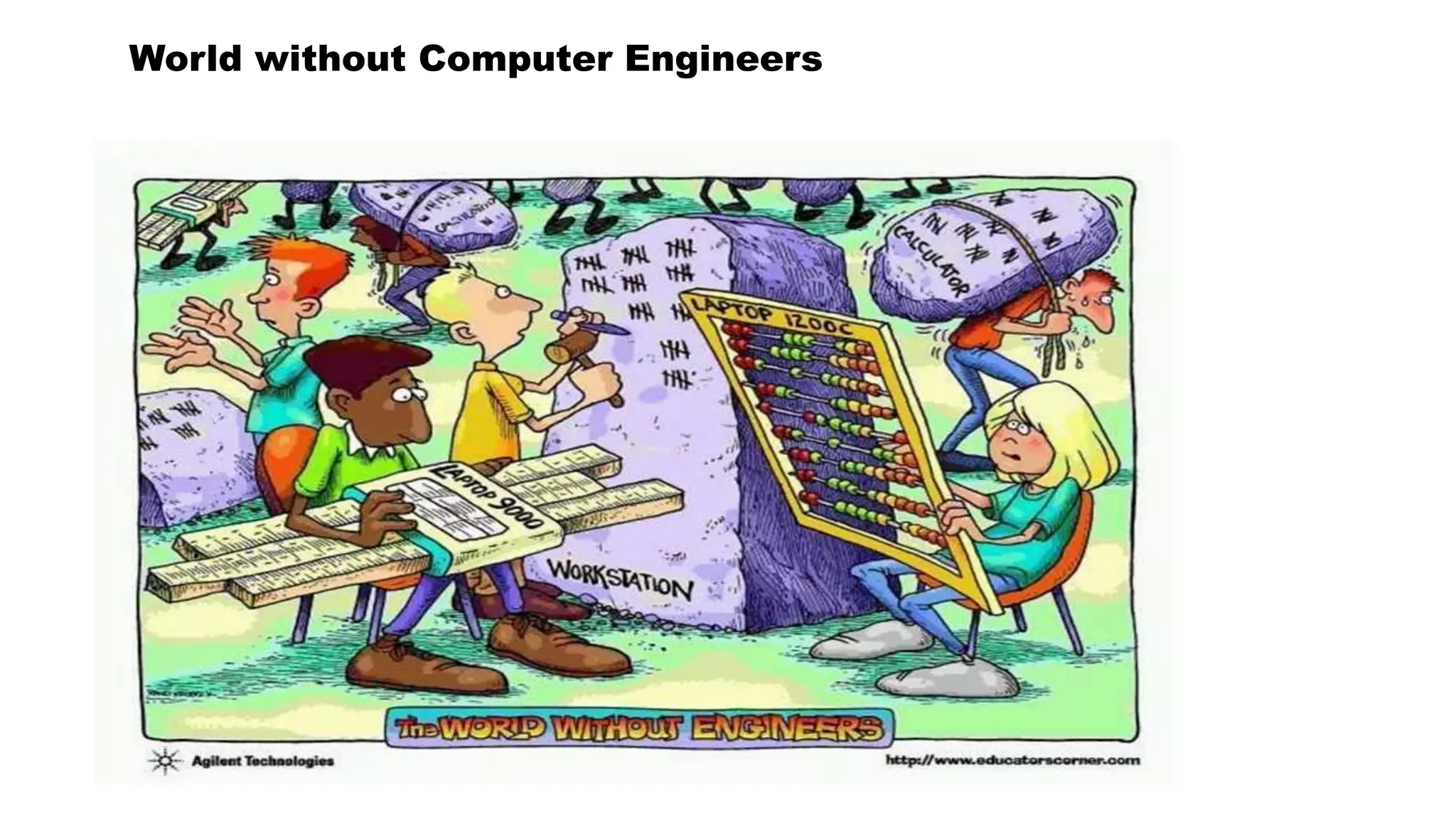
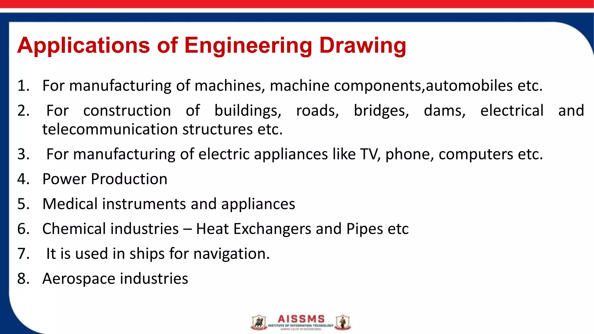
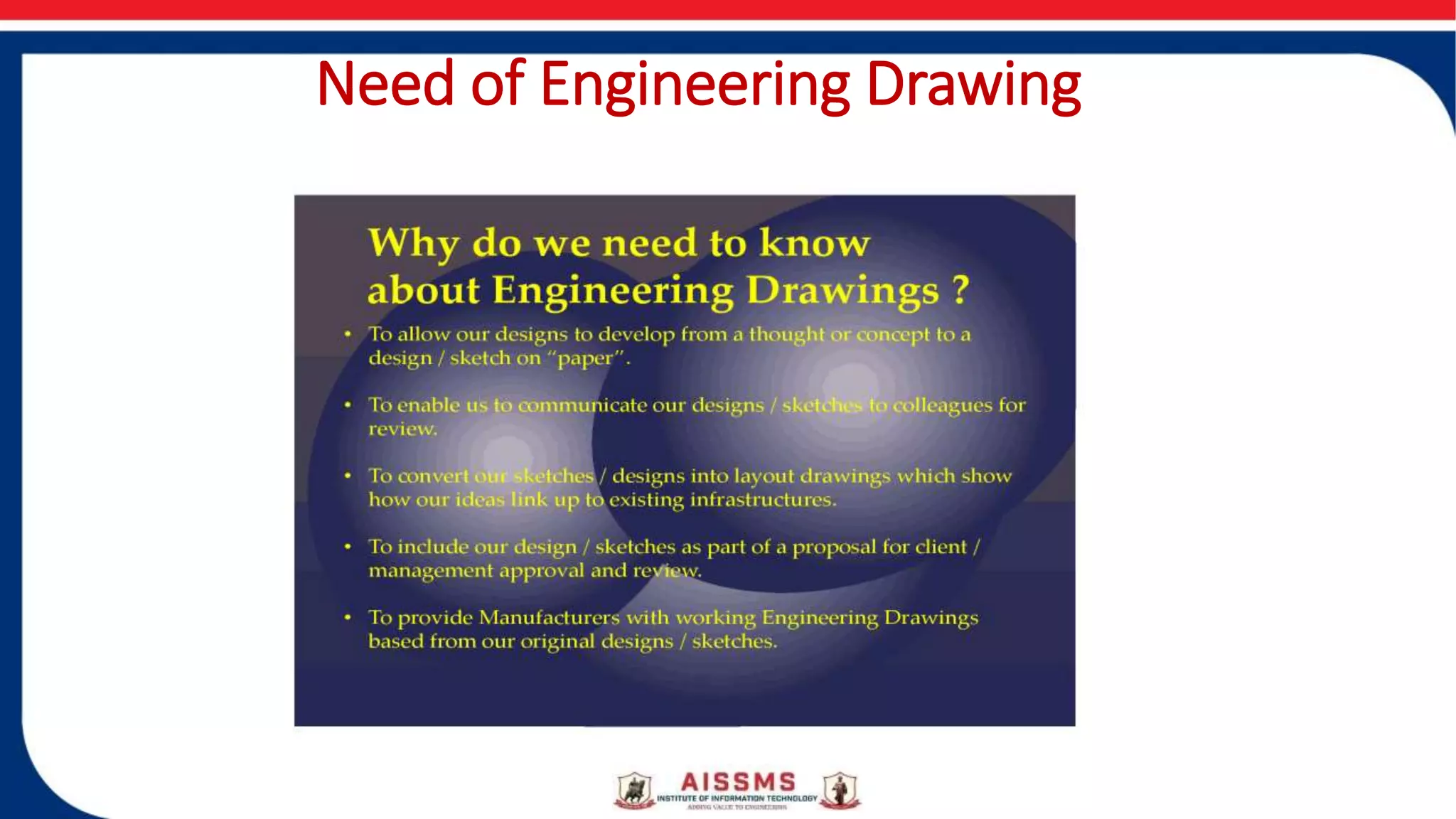
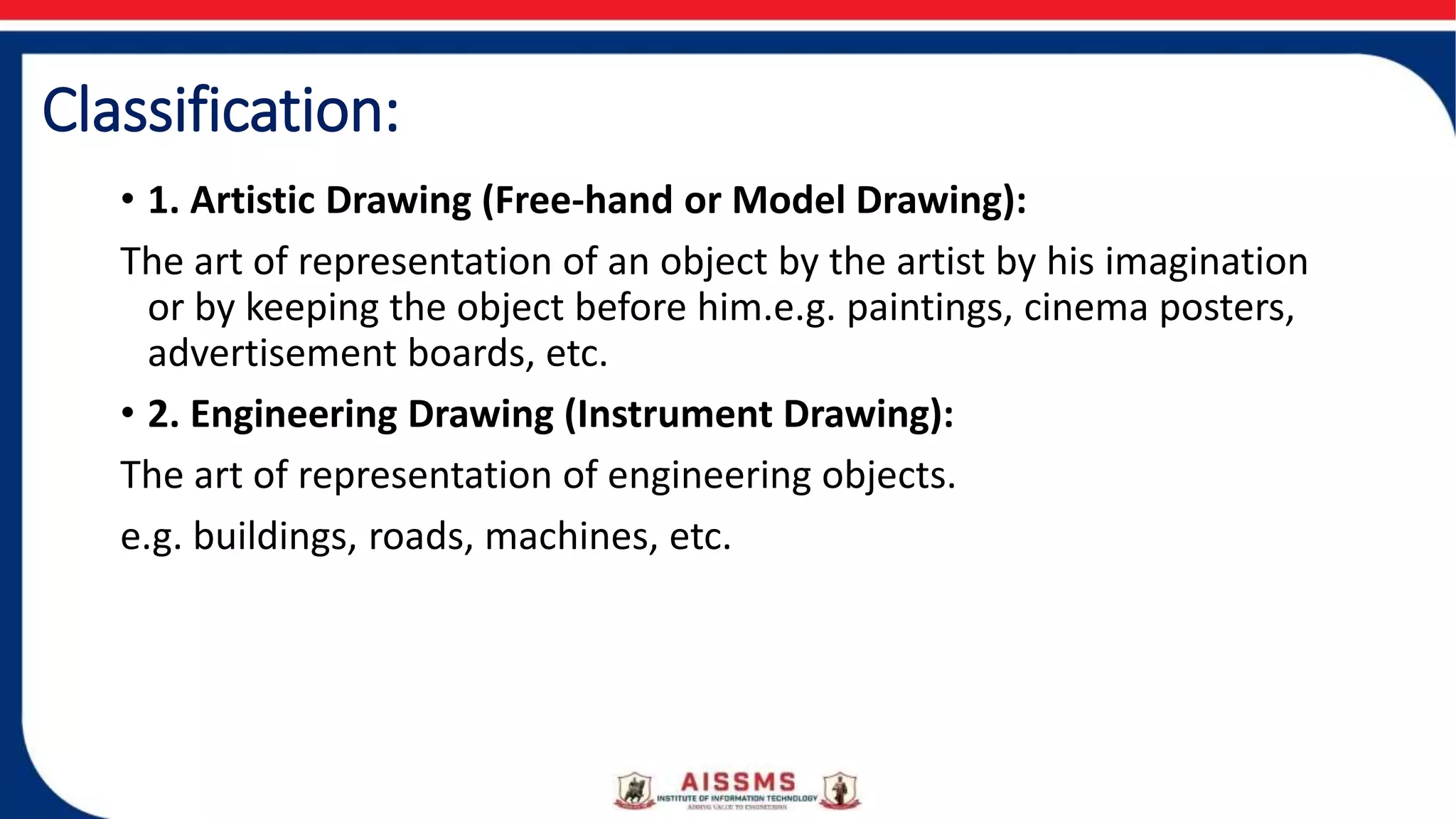
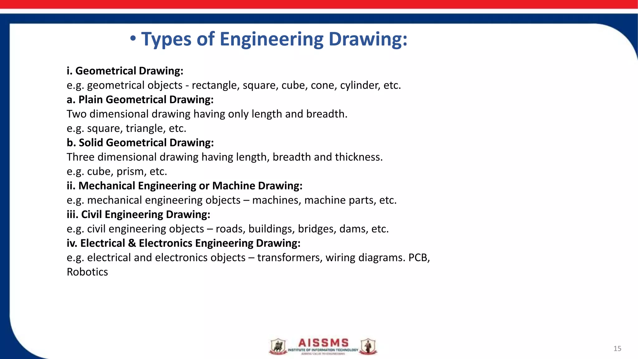
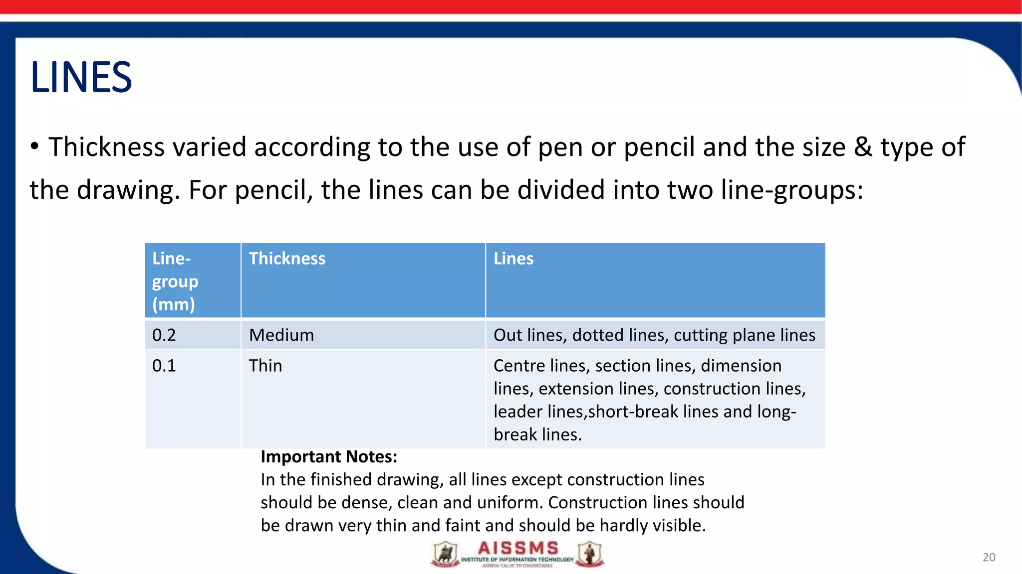
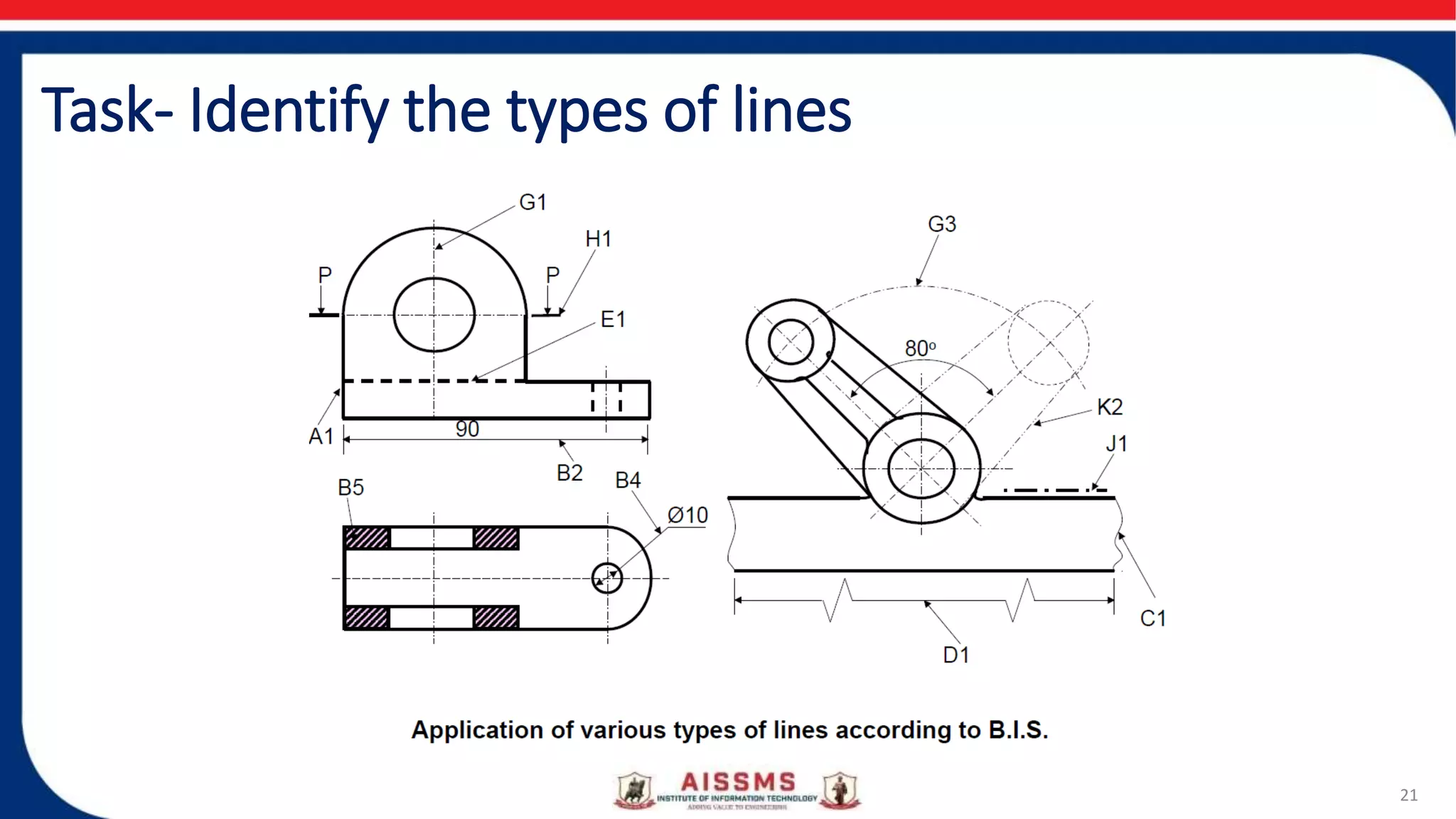
2. Contents:
• Concept of Engineering Drawing/Graphics
• Need of Engineering Drawing
• Applications of Engineering Drawing
• Types of Lines
3. 3
Engineering Drawing and Graphics
• Bertoline et al. “Drawing is the process of conceiving or inventing ideas and
communicating those ideas to others in a form that is understood easily.”
• Eide , “Engineering design is a systematic process by which solutions to the
needs of humankind are obtained.”
• Lockhart et al. “Design is the act of creating the specifications for a product
or process that best satisfies the design criteria.”
• The graphical representation of any object or idea can be termed as
drawing. A drawing can be prepared either using free hand or using
engineering instruments or using computer program
4. Engineering Drawing
• Engineering drawing can be defined as a graphical language used by engineers
and other technical personnel associated with the engineering profession
which fully and clearly defines the requirements for engineered items.
• In other words, The art of representing a real or imaginary object precisely
using some graphics, symbols, letters and numbers with the help of
engineering drawing instruments is called engineering drawing.
• The art of representing engineering objects such as buildings, roads, machines,
circuits etc. on a paper is called engineering drawing.
4
10. Applications of Engineering Drawing
1. For manufacturing of machines, machine components,automobiles etc.
2. For construction of buildings, roads, bridges, dams, electrical and
telecommunication structures etc.
3. For manufacturing of electric appliances like TV, phone, computers etc.
4. Power Production
5. Medical instruments and appliances
6. Chemical industries – Heat Exchangers and Pipes etc
7. It is used in ships for navigation.
8. Aerospace industries
13. The Role of Graphics
•Visualization
•Communication
•Documentation
14. Classification:
• 1. Artistic Drawing (Free-hand or Model Drawing):
The art of representation of an object by the artist by his imagination
or by keeping the object before him.e.g. paintings, cinema posters,
advertisement boards, etc.
• 2. Engineering Drawing (Instrument Drawing):
The art of representation of engineering objects.
e.g. buildings, roads, machines, etc.
15. 15
• Types of Engineering Drawing:
i. Geometrical Drawing:
e.g. geometrical objects - rectangle, square, cube, cone, cylinder, etc.
a. Plain Geometrical Drawing:
Two dimensional drawing having only length and breadth.
e.g. square, triangle, etc.
b. Solid Geometrical Drawing:
Three dimensional drawing having length, breadth and thickness.
e.g. cube, prism, etc.
ii. Mechanical Engineering or Machine Drawing:
e.g. mechanical engineering objects – machines, machine parts, etc.
iii. Civil Engineering Drawing:
e.g. civil engineering objects – roads, buildings, bridges, dams, etc.
iv. Electrical & Electronics Engineering Drawing:
e.g. electrical and electronics objects – transformers, wiring diagrams. PCB,
Robotics
16. Drawing Instruments and Other Drawing Materials:
16
1. Drawing Board 11. French Curve
2. Drawing Sheets A2 size 12. Drawing Pencils – H, 2H, 4H,HB
3. Drawing Sheet Holder 13. Sand Paper
4. Set-squares – 45o and 30o – 60o 14. Eraser (Rubber)
5. Large size Compass 15. Drawing Pins and Clips
6. Small bow Compass 16. Cello Tape
7. Large size Divider 17. Duster or Handkerchief
8. Small bow Divider 18. Drafting Machine/ Mini Drafter
9. Scales – 6” and 12” 19. Sketch Book A2 size and A3 Size Spiral binding
10. Protractor 20. Roller Scale (Medium size)
21. Pencil Sharpener 22. Sheet Folder
20. LINES
• Thickness varied according to the use of pen or pencil and the size & type of
the drawing. For pencil, the lines can be divided into two line-groups:
20
Line-
group
(mm)
Thickness Lines
0.2 Medium Out lines, dotted lines, cutting plane lines
0.1 Thin Centre lines, section lines, dimension
lines, extension lines, construction lines,
leader lines,short-break lines and long-
break lines.
Important Notes:
In the finished drawing, all lines except construction lines
should be dense, clean and uniform. Construction lines should
be drawn very thin and faint and should be hardly visible.