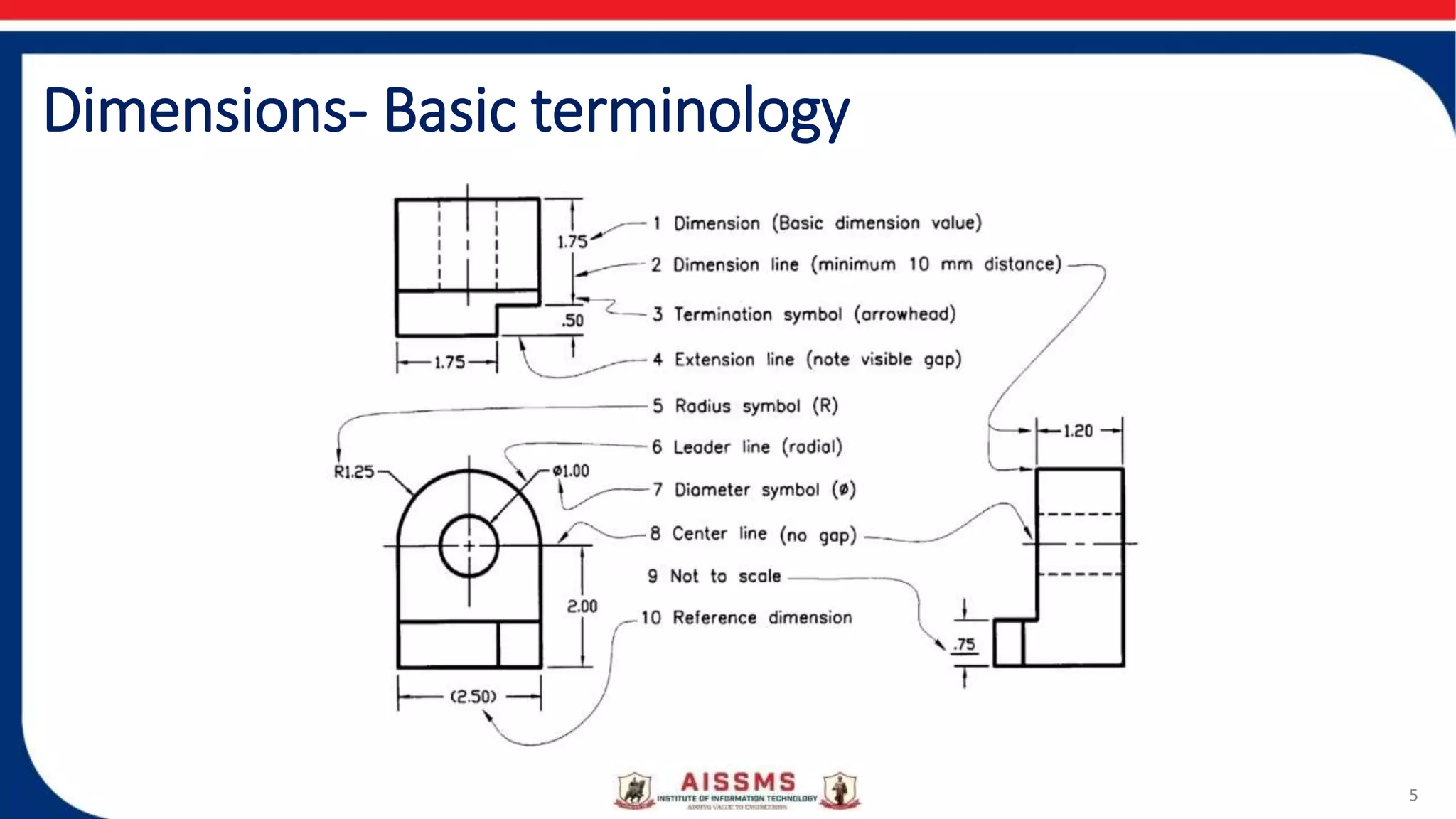
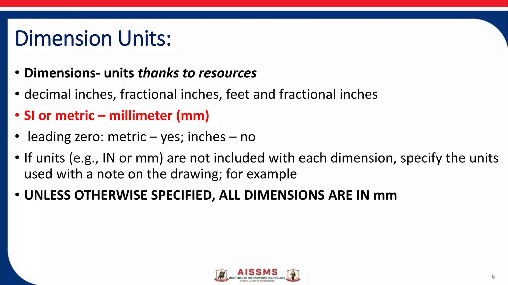
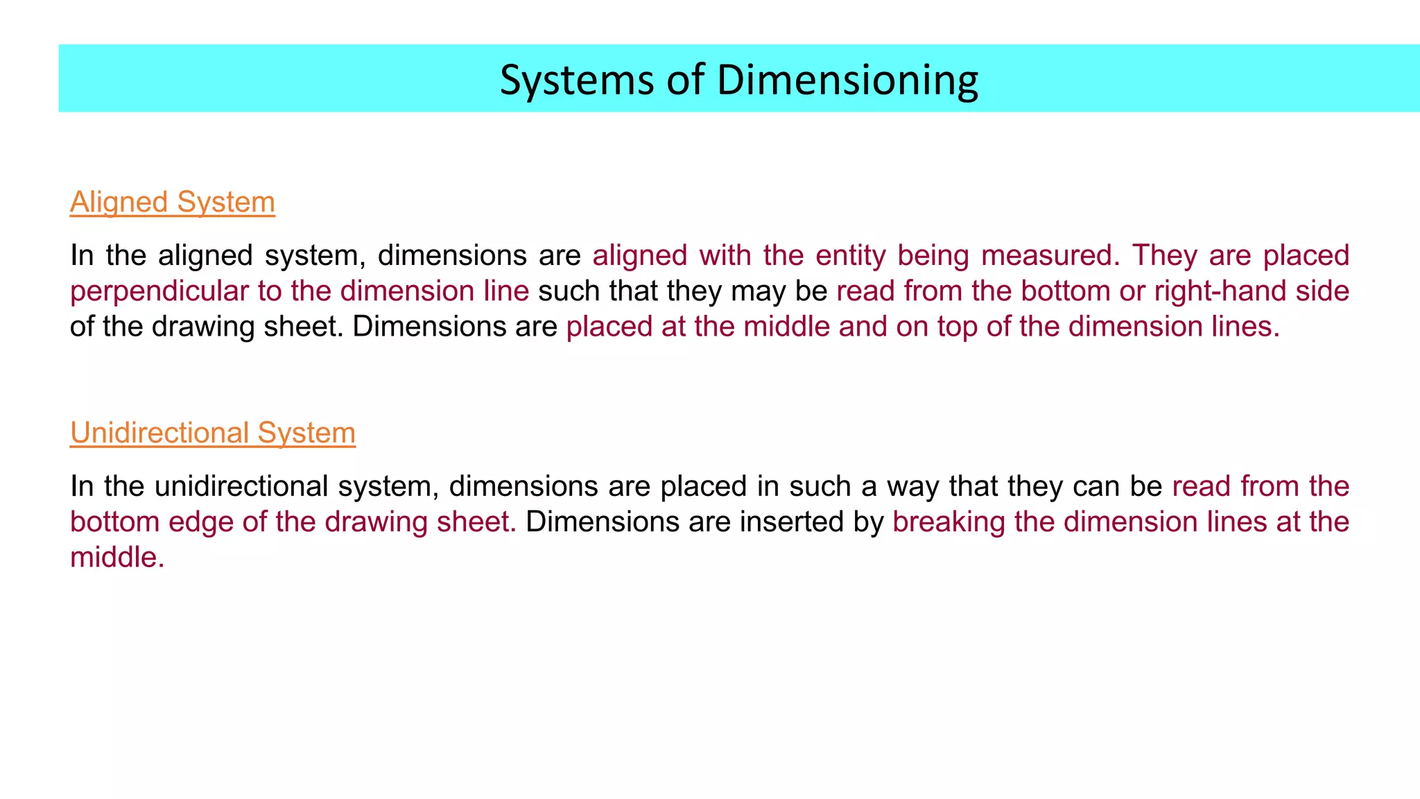
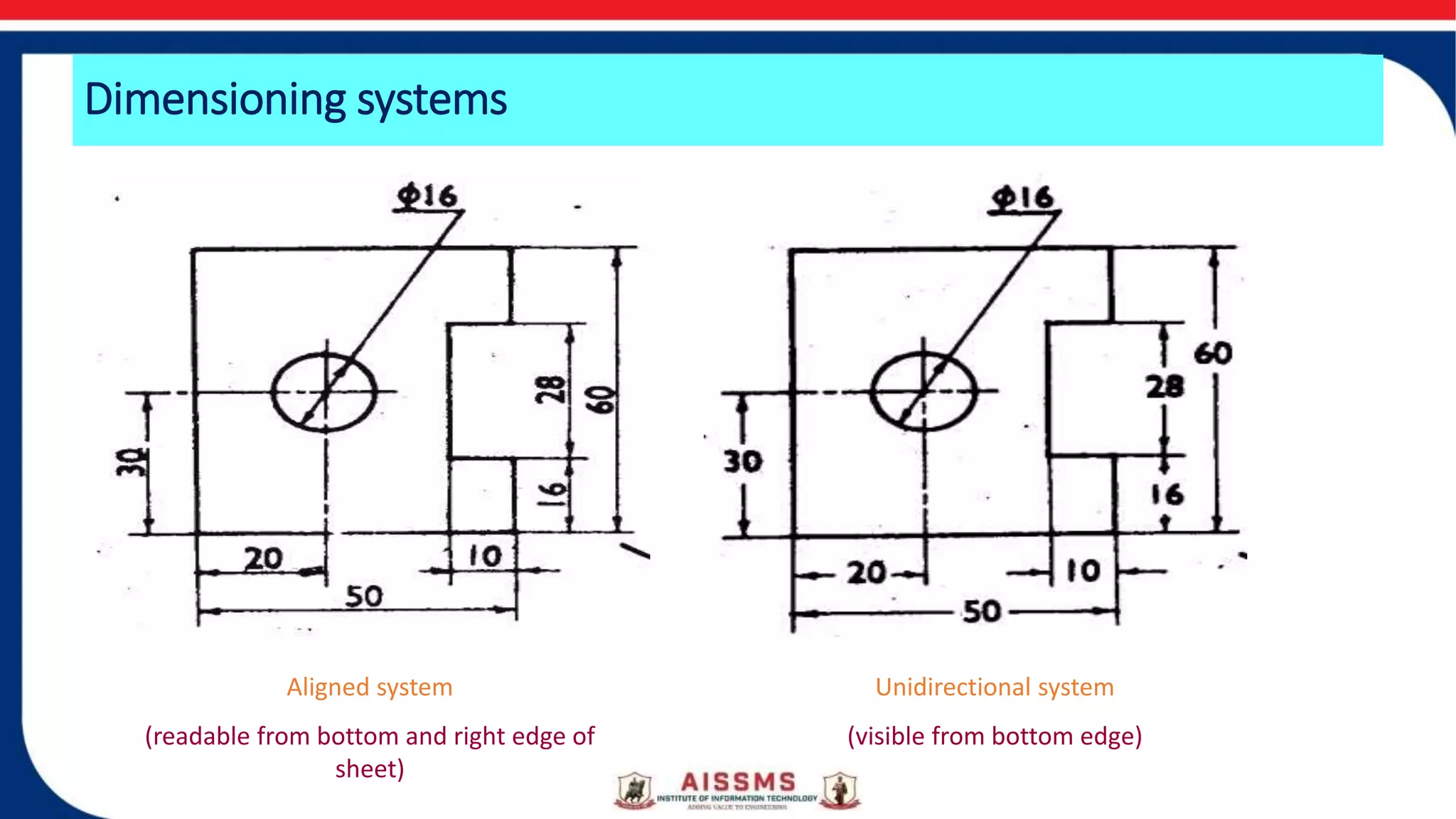
Basic of Engineering Drawing
Part-3
Dimensioning Rules
By
Prof. A.J.More
Department of Engineering Sciences
Contents:
• What are dimensions
• Fundamental rules of dimensioning
• Guidelines for good dimensioning in engineering drawings
Dimensions
• What are dimensions
• We use dimension to represent size and position (of the designed/modeled
shape)
• DIMENSION is a numerical value expressed in appropriate units of
measurement and used to define the size, location, orientation, form
or other geometric characteristics of a part.
• A method of communication to machinists in the Production facility
3
Types of Diamensions:
• Different kinds:
• Linear
• Angular
• Radius/diameter
• Reference
4
Dimensions- Basic terminology
5
Dimension Units:
• Dimensions- units thanks to resources
• decimal inches, fractional inches, feet and fractional inches
• SI or metric – millimeter (mm)
• leading zero: metric – yes; inches – no
• If units (e.g., IN or mm) are not included with each dimension, specify the units
used with a note on the drawing; for example
• UNLESS OTHERWISE SPECIFIED, ALL DIMENSIONS ARE IN mm
6
Aligned System
In the aligned system, dimensions are aligned with the entity being measured. They are placed
perpendicular to the dimension line such that they may be read from the bottom or right-hand side
of the drawing sheet. Dimensions are placed at the middle and on top of the dimension lines.
Unidirectional System
In the unidirectional system, dimensions are placed in such a way that they can be read from the
bottom edge of the drawing sheet. Dimensions are inserted by breaking the dimension lines at the
middle.
Systems of Dimensioning
Dimensioning systems
Aligned system
(readable from bottom and right edge of
sheet)
Unidirectional system
(visible from bottom edge)
Thank You

Basic of engineering drawing part 3 v3

  • 1.
    Basic of EngineeringDrawing Part-3 Dimensioning Rules By Prof. A.J.More Department of Engineering Sciences
  • 2.
    Contents: • What aredimensions • Fundamental rules of dimensioning • Guidelines for good dimensioning in engineering drawings
  • 3.
    Dimensions • What aredimensions • We use dimension to represent size and position (of the designed/modeled shape) • DIMENSION is a numerical value expressed in appropriate units of measurement and used to define the size, location, orientation, form or other geometric characteristics of a part. • A method of communication to machinists in the Production facility 3
  • 4.
    Types of Diamensions: •Different kinds: • Linear • Angular • Radius/diameter • Reference 4
  • 5.
  • 6.
    Dimension Units: • Dimensions-units thanks to resources • decimal inches, fractional inches, feet and fractional inches • SI or metric – millimeter (mm) • leading zero: metric – yes; inches – no • If units (e.g., IN or mm) are not included with each dimension, specify the units used with a note on the drawing; for example • UNLESS OTHERWISE SPECIFIED, ALL DIMENSIONS ARE IN mm 6
  • 7.
    Aligned System In thealigned system, dimensions are aligned with the entity being measured. They are placed perpendicular to the dimension line such that they may be read from the bottom or right-hand side of the drawing sheet. Dimensions are placed at the middle and on top of the dimension lines. Unidirectional System In the unidirectional system, dimensions are placed in such a way that they can be read from the bottom edge of the drawing sheet. Dimensions are inserted by breaking the dimension lines at the middle. Systems of Dimensioning
  • 8.
    Dimensioning systems Aligned system (readablefrom bottom and right edge of sheet) Unidirectional system (visible from bottom edge)
  • 9.