Downloaded 360 times

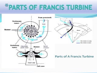
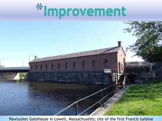


The Francis turbine is an inward flow reaction turbine with radial discharge at the outlet. It is a mixed-flow turbine where water enters the runner radially and exits axially. Francis turbines are used in applications with medium head between 45-250 meters. They have medium specific speeds between 50-250 and a vertically oriented shaft. Francis turbines are widely used worldwide due to their high efficiencies between 80-94%. However, they also have high costs due to their complex design and cavitation can be an issue.


![[PPT] on Steam Turbine](https://cdn.slidesharecdn.com/ss_thumbnails/spsharmafinalppt-140608082156-phpapp01-thumbnail.jpg?width=640&height=640&fit=bounds)


