INDEX
1. Introduction
2. Usesof Compressed air
3. Reciprocating compressors
4. Operation of a compressors
5. Work of compression
6. Power required
7. Reciprocating compressor efficiencies
8. Multistage reciprocating compressors
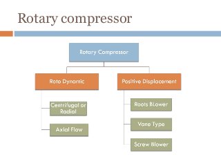
9. Rotary compressors
3.
Introduction
•
•
•
•
•
The machine whichtakes in air or any other gas
at low pressure and compresses it to high
pressure are called compressors.
They are power consuming machines in which
mechanical work is converted into the pressure
head of air or gas.
They are also considered as reversed heat
engine.
Generally, the compressors are driven by electric
motors, I.C. engine or gas turbines.
A compressor is used for increasing the pressure
of air is called air compressor.
4.
Uses of compresed air
In refrigeration cycle
Operation tools like drill hammers etc.
Filling the air in automobile tyres
Spray painting
Increasing inlet pressure of I.C. engine
To operate air motor I mines where fire risk are more
Pumping water
Gas turbine power plant
Conveying the materials like sand and concrete along
a pipe line
For sand blasting
Operating blast furnace
Operating air brakes used in buses truck trains etc.
5.
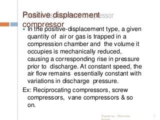
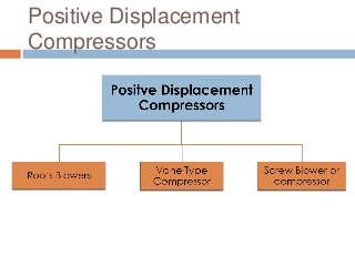
Positive displacement
compressor Inthe positive-displacement type, a given
quantity of air or gas is trapped in a
compression chamber and the volume it
occupies is mechanically reduced,
causing a corresponding rise in pressure
prior to discharge. At constant speed, the
air flow remains essentially constant with
variations in discharge pressure.
Ex: Reciprocating compressors, screw
compressors, vane compressors & so
on.
Prepare by :- Shivkumar 7
6.
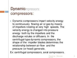
Dynamic
compressors:
Dynamic compressorsimpart velocity energy
to continuously flowing air or gas by means
of impellers rotating at very high speeds. The
velocity energy is changed into pressure
energy both by the impellers and the
discharge volutes or diffusers. In the
centrifugal-type dynamic compressors, the
shape of the impeller blades determines the
relationship between air flow and the
pressure (or head) generate.
Ex: centrifugal compressors, axial compressors.
Prepare by :- Shivkumar 8
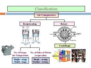
Classification of compressors
(1)Method of compression
•
•
•
Reciprocating compressors:.
Rotary compressors:
Centrifugal compressors
(2) Delivery pressure
•
•
•
•
Low pressure
Medium pressure
High pressure
Very high pressure
9.
(3) Principal ofoperation
Positive of displacement
Rotodynamic or steady flow compressor
(4) The number of stages
Single stage compressor - pressure up to 5 bar
Multistage compressor - pressure above 5 bar
(5) The number of cylinder
Single cylinder
Multi cylinder
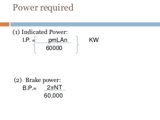
10.
(6) Volume ofair delivered
•
•
• Low capacity
Medium capacity
High capacity
(7) Fluid to be compres ed
•
•
• Air compressor
Gas compressor
Vapour compressor
11.
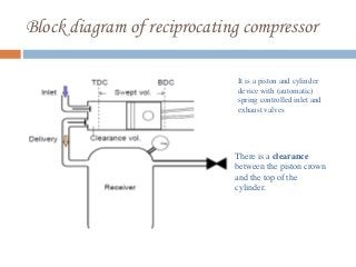
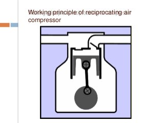
Block diagram ofreciprocating compressor
It is a piston and cylinder
device with (automatic)
spring controlled inlet and
exhaust valves
There is a clearance
between the piston crown
and the top of the
cylinder.
12.
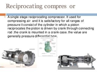
Reciprocating compres or
A single stage reciprocating compressor. It used for
compressing air and it is satisfactory for all ranges of
pressure it consist of the cylinder in which a piston
reciprocates the piston is driven by crank through connecting
rod .the crank is mounted in a crank case. the value are
generally pressure differential type.
13.
Reciprocating
compressors
r usually
has tw
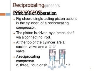
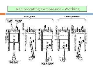
Principleof Operation
Fig shows single-acting piston actions
in the cylinder of a reciprocating
compressor.
The piston is driven by a crank shaft
via a connecting rod.
At the top of the cylinder are a
suction valve and a discharge
valve.
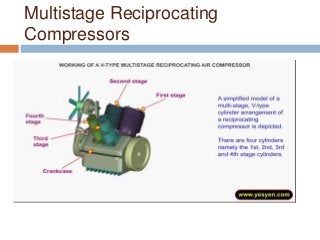
A reciprocating
compresso
o, three, four, or six cylinders in it.
9
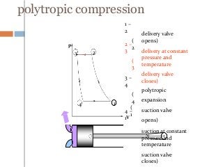
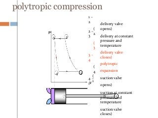
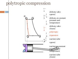
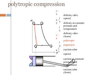
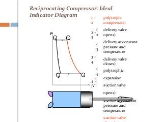
Reciprocating Compressor –Equation for Work
Pressure
P1
P2
3 2’ 2 2”
4 1 (Polytropic)
PV n
C
PV C
(Isothermal)
PV
C
(Adiabatic)
V2 V1
Volume
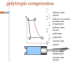
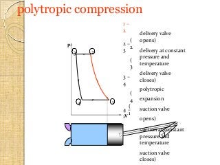
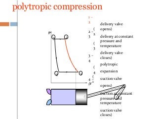
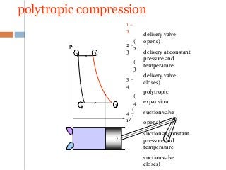
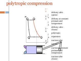
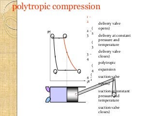
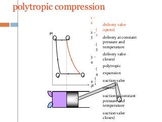
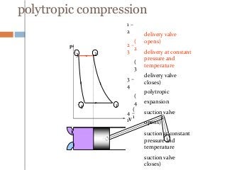
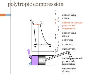
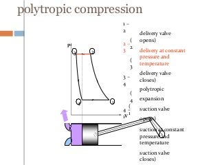
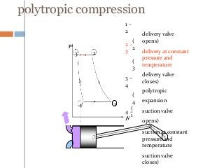
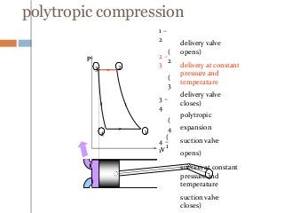
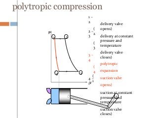
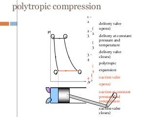
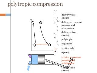
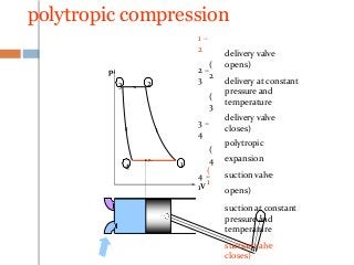
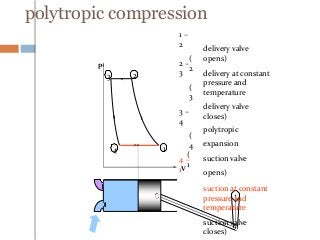
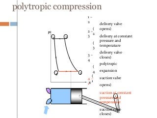
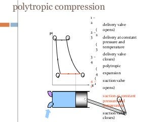
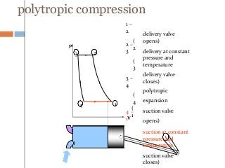
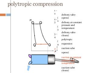
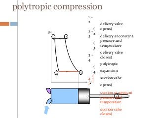
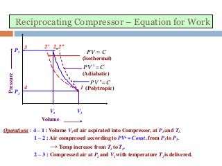
Operations : 4 – 1 : Volume V1 of air aspirated into Compressor, at P1 and T1.
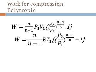
1 – 2 : Air compressed according to PVn = Const. from P1 to P2.
→ Temp increase from T1 to T2.
2 – 3 : Compressed air at P2 and V2 with temperature T2 is delivered.
48.
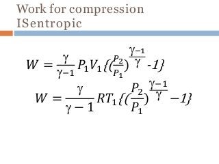
Reciprocating Compressor –Equation for Work
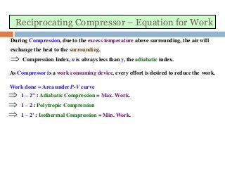
During Compression, due to the excess temperature above surrounding, the air will
exchange the heat to the surrounding.
Compression Index, n is always less than γ, the adiabatic index.
As Compressor is a work consuming device, every effort is desired to reduce the work.
Work done = Area under P-V curve
1 – 2” : Adiabatic Compression = Max. Work.
1 – 2 : Polytropic Compression
1 – 2’ : Isothermal Compression = Min. Work.
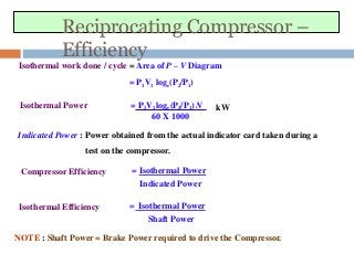
Reciprocating Compressor –
Efficiency
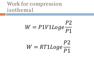
Isothermalwork done / cycle = Area of P – V Diagram
= P1V1 loge(P2/P1)
Isothermal Power = P1V1 loge(P2/P1) N kW
60 X 1000
Indicated Power : Power obtained from the actual indicator card taken during a
test on the compressor.
Compressor Efficiency = Isothermal Power
Indicated Power
Isothermal Efficiency = Isothermal Power
Shaft Power
NOTE : Shaft Power = Brake Power required to drive the Compressor.
53.
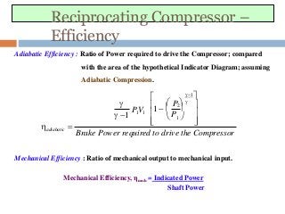
Reciprocating Compressor –
Efficiency
AdiabaticEfficiency : Ratio of Power required to drive the Compressor; compared
with the area of the hypothetical Indicator Diagram; assuming
Adiabatic Compression.
Brake Power required to drive the Compressor
adiabatic
1
1
P2
1
P
1
P1V1
Mechanical Efficiency : Ratio of mechanical output to mechanical input.
Mechanical Efficiency, ηmech = Indicated Power
Shaft Power
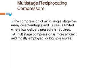
Multistage Reciprocating
Compressors
The compressionof air in single stage has
many disadvantages and its use is limited
where low delivery pressure is required.
A multistage compression is more efficient
and mostly employed for high pressures.
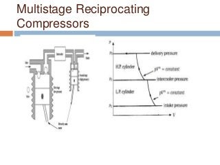
Reciprocating Compressor –
Multistage
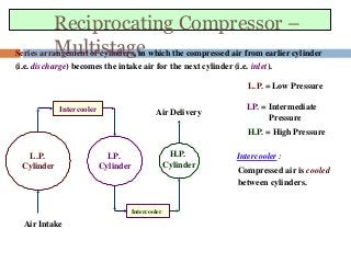
Intercooler:
Compressed air is cooled
between cylinders.
Series arrangement of cylinders, in which the compressed air from earlier cylinder
(i.e. discharge) becomes the intake air for the next cylinder (i.e. inlet).
L.P. = Low Pressure
I.P. = Intermediate
Pressure
H.P. = High Pressure
L.P.
Cylinder
I.P.
Cylinder
H.P.
Cylinder
Intercooler
Intercooler
Air Intake
Air Delivery
62.
Reciprocating Compressor –
Multistage
IntakePr.
P1 or Ps
P3 or Pd
2
1
PV n
C
8
Delivery Pr. 6 9 3 5
Intermediate Pr. 7 4
P2 PVC
Without Intercooling
Perfect Intercooling
L.P.
H.P.
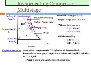
Overall Pr. Range : P1 – P3
Single – stage cycle : 8-1-5-6
Without Intercooling :
L.P. : 8-1-4-7
H.P. : 7-4-5-6
With Intercooling :
L.P. : 8-1-4-7
H.P. : 7-2-3-6
Volume
Perfect Intercooling : After initial compression in L.P. cylinder, air is cooled in the
Intercooler to its original temperature, before entering H.P. cylinder
i.e. T2 = T1 OR
Points 1 and 2 are on SAME Isothermal line.
63.
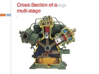
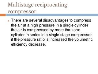
Multistage reciprocating
compressor
Thereare several disadvantages to compress
the air at a high pressure in a single cylinder
the air is compressed by more than one
cylinder in series in a single stage compressor
if the pressure ratio is increased the volumetric
efficiency decrease.
64.
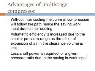
Advantages of multistage
compressor
•
•
•Without inter cooling the curve of compression
will follow the path hence the saving work
input due to inter cooling .
Volumetric efficiency is increased due to the
smaller pressure range as the effect of
expansion of air in the clearance volume is
less
Less shaft power is required for a given
pressure ratio due to the saving in work input
65.
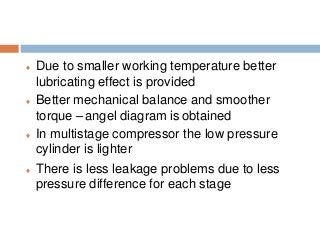
Due tosmaller working temperature better
lubricating effect is provided
Better mechanical balance and smoother
torque – angel diagram is obtained
In multistage compressor the low pressure
cylinder is lighter
There is less leakage problems due to less
pressure difference for each stage
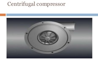
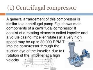
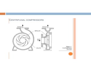
(1) Centrifugal compressor
•
heair enter
he
A general arrangement of this compressor is
similar to a centrifugal pump Fig. shows main
components of a centrifugal compressor It
consist of a rotating elements called impeller and
a volute casing impeller rotates at a very high
speed may be up to 30,000 RPM T
into the compressor through the
suction eye of the impeller. due to t
rotation of the impeller at a high
velocity.
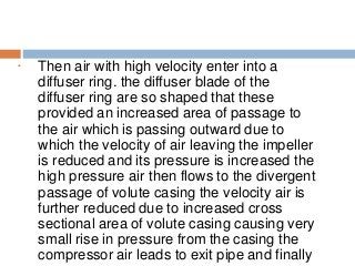
70.
• Then airwith high velocity enter into a
diffuser ring. the diffuser blade of the
diffuser ring are so shaped that these
provided an increased area of passage to
the air which is passing outward due to
which the velocity of air leaving the impeller
is reduced and its pressure is increased the
high pressure air then flows to the divergent
passage of volute casing the velocity air is
further reduced due to increased cross
sectional area of volute casing causing very
small rise in pressure from the casing the
compressor air leads to exit pipe and finally
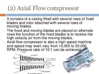
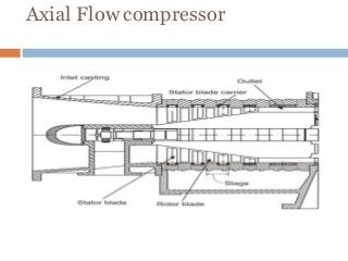
(2) Axial Flowcompressor
•
•
•
It consists of a casing fitted with several rows of fixed
blades and rotor attached with several rows of
moving blades.
The fixed and moving blades are placed on alternate
rows the function of the fixed blades is to receive the
high velocity air from the moving blades.
Axial flow compressor is also a high speed machine
and speed may even vary from 10,000 to 30,000
RPM. Pressure ratio of 10:1 can be achieved.
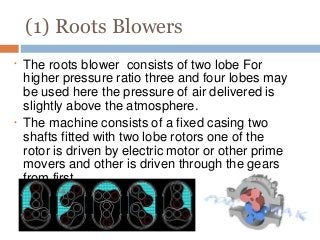
(1) Roots Blowers
•
•
Theroots blower consists of two lobe For
higher pressure ratio three and four lobes may
be used here the pressure of air delivered is
slightly above the atmosphere.
The machine consists of a fixed casing two
shafts fitted with two lobe rotors one of the
rotor is driven by electric motor or other prime
movers and other is driven through the gears
from first.
79.
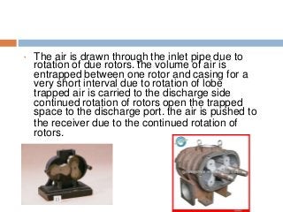
• The airis drawn through the inlet pipe due to
rotation of due rotors. the volume of air is
entrapped between one rotor and casing for a
very short interval due to rotation of lobe
trapped air is carried to the discharge side
continued rotation of rotors open the trapped
space to the discharge port. the air is pushed to
the receiver due to the continued rotation of
rotors.
(2) Vane typecompressor or
Blower
•
• ein the slots. The volum
ion
the
eated
nd
ed to
into
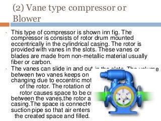
This type of compressor is shown inn fig. The
compressor is consists of rotor drum mounted
eccentrically in the cylindrical casing. The rotor is
provided with vanes in the slots. These vanes or
blades are made from non-metallic material usually
fiber or carbon.
The vanes can slide in and out
between two vanes keeps on
changing due to eccentric mot
of the rotor. The rotation of
rotor causes space to be cr
between the vanes,the rotor a
casing.The space is connect
suction pipe so that air enters
the created space and filled.
82.
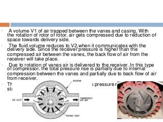
• A volumeV1 of air trapped between the vanes and casing. With
the rotation of rotor of rotor, air gets compressed due to reduction of
space towards delivery side.
• The fluid volume reduces to V2,when it communicates with the
delivery side. Since the receiver pressure is higher than the
compressed air between the vanes, the back flow of air from the
receiver will take place.
• Due to rotation of vanes air is delivered to the receiver. In this type
of compressor. the total pressure rise is partially due to internal
compression between the vanes and partially due to back flow of air
from receiver.
• Th a pressure ratio up to 6 per
sta
is type of compressor can produce
ge
83.
Reciprocating Compressor –
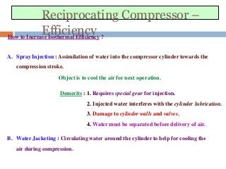
EfficiencyHowto Increase Isothermal Efficiency ?
A. Spray Injection : Assimilation of water into the compressor cylinder towards the
compression stroke.
Object is to cool the air for next operation.
Demerits : 1. Requires special gear for injection.
2. Injected water interferes with the cylinder lubrication.
3. Damage to cylinder walls and valves.
4. Water must be separated before delivery of air.
B. Water Jacketing : Circulating water around the cylinder to help for cooling the
air during compression.


![Reciprocating Compressor –
Efficiency
Volumetric Efficiency :
Volumetric Efficiency :.
Efficiency, ηvol =1 - C [(p2/p1)1/-1)]
c=
𝑉𝑐
𝑉𝑠](https://image.slidesharecdn.com/compressor-180910082139/85/Compressor-by-Patait-S-B-54-320.jpg?cb=1756115335)
![Reciprocating compres or
efficiencies
(1) Mechanical efficiency
ῃ=I.P/B.P
(2) Isothermal efficiency
ῃiso=
p1 V1 loge (p2/P1)
[ (n/n-1) p1V1 (p2/p1)n-1/n -1}]](https://image.slidesharecdn.com/compressor-180910082139/85/Compressor-by-Patait-S-B-56-320.jpg?cb=1756115335)


![SBP- Air compressor [Compatibility Mode].pdf](https://cdn.slidesharecdn.com/ss_thumbnails/sbp-aircompressorcompatibilitymode-241227102120-b6a67cde-thumbnail.jpg?width=640&height=640&fit=bounds)


