Downloaded 21 times
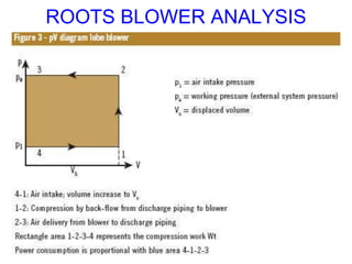
![ROOTS BLOWER ANALYSIS
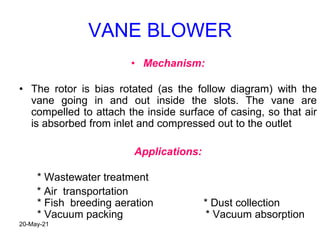
• Work required to drive the root blower with two lobes per
revolution
• W = V (P2-P1)
Note: V= 4V for 2 lobe rotor and 6V for 3 lobe rotor
• Volume of air compressed per minute (Va) = 4V*N [ for 2 lobe]
Where N = speed of blower in RPM
- ACTAUL POWER REQUIRED TO COMPRESS Va AIR in
m3/min = Pa = Va (P2-P1)
- IDEAL POWER REQUIRED TO COMPRESS Va AIR in
m3/min = Pi = (γ/ γ-1) P1 Va [(p2/P1)(γ-1/ γ) - 1]
(The same relation we’ve derived for reciprocating compressor in class )
- Root Efficiency = Ideal Power/Actual Power
20-May-21](https://image.slidesharecdn.com/rotarycompressorsppt-210520170404/85/Rotary-compressors-ppt-8-320.jpg)
![Root Blower Efficiency
- Root Efficiency = Ideal Power/Actual Power
= (γ/ γ-1) P1 Va [(p2/P1)(γ-1/ γ) - 1]
Va(P2-P1)
OR
ROOT EFFICIENCY = (γ/ γ-1) [(rp) )(γ-1/ γ) - 1]
[rp-1]
Where rp is the pressure ratio
20-May-21](https://image.slidesharecdn.com/rotarycompressorsppt-210520170404/85/Rotary-compressors-ppt-9-320.jpg)
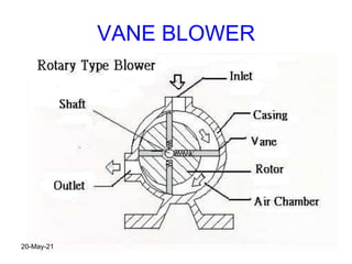
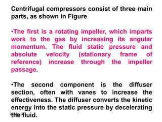
![VANE BLOWER ANALYSIS
1
2
c
P1
Pc
P2
P
V
Pressure rise due to
back flow of air
Pressure rise due to
internal compression
Total pressure rise = Internal compression pressure rise + Back flow
W = W1-c + Wc-2
W = (γ/ γ-1) P1 V1 [(Pc/P1)(γ-1/ γ) - 1] + Vc (P2-PC)
Also P1V1γ = Pc Vc
γ
So, W = (γ/ γ-1) P1 V1 [(Pc/P1)(γ-1/ γ) - 1] + (P1/Pc)(1/ γ) V1 (P2-Pc)
20-May-21](https://image.slidesharecdn.com/rotarycompressorsppt-210520170404/85/Rotary-compressors-ppt-12-320.jpg)

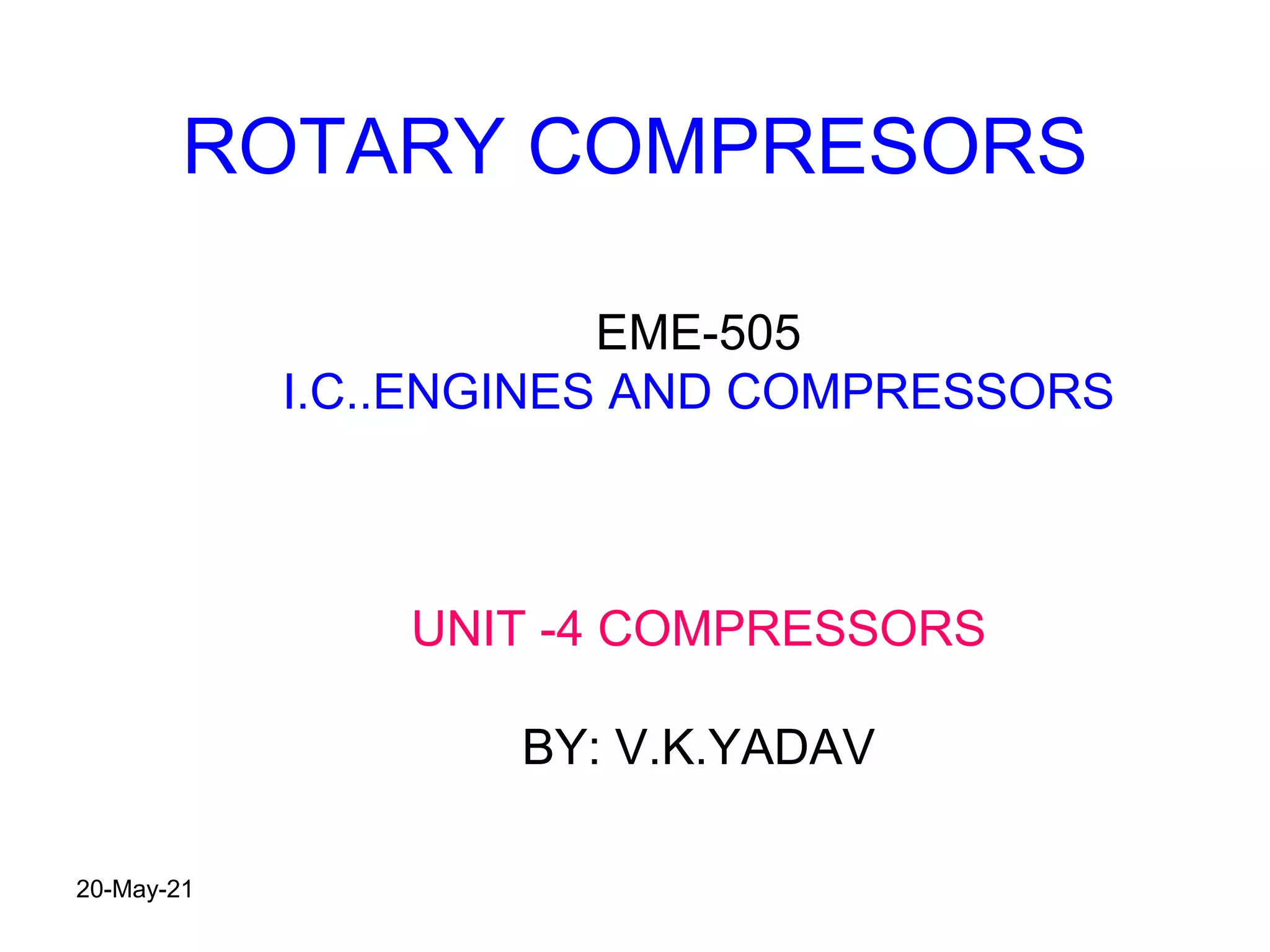
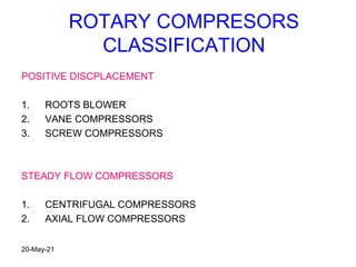
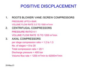
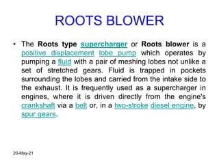
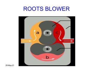
This document discusses different types of compressors used in mechanical engineering. It covers positive displacement compressors like roots blowers, vane compressors, and screw compressors. It also discusses steady flow compressors such as centrifugal and axial flow compressors. For each type of compressor, the document provides details on their working principles, applications, pressure ratios, flow rates and comparative advantages.


