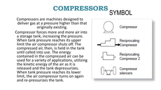
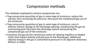
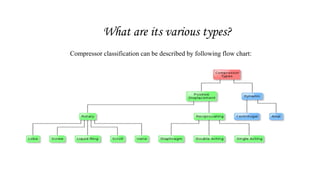
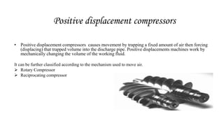
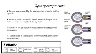
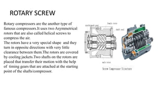
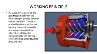
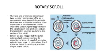
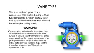
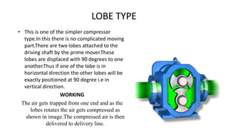
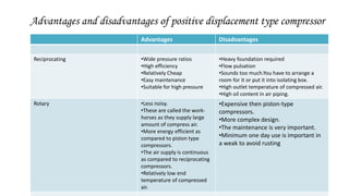
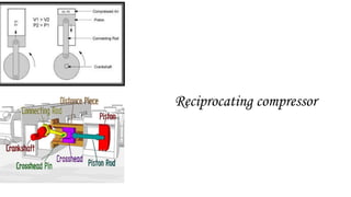
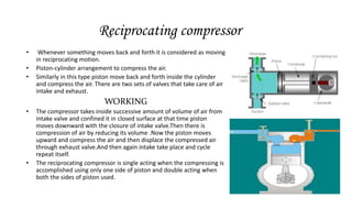
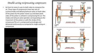
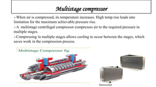
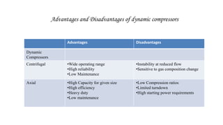
2. COMPRESSORS
Compressors are machines designed to
deliver gas at a pressure higher than that
originally existing.
Compressor forces more and more air into
a storage tank, increasing the pressure.
When tank pressure reaches its upper
limit the air compressor shuts off. The
compressed air, then, is held in the tank
until called into use. The energy
contained in the compressed air can be
used for a variety of applications, utilizing
the kinetic energy of the air as it is
released and the tank depressurizes.
When tank pressure reaches its lower
limit, the air compressor turns on again
and re-pressurizes the tank.
SYMBOL
3. Compression methods
The methods employed to achieve compression are:
• Trap consecutive quantities of gas in some type of enclosure, reduce the
volume, thus increasing the pressure, then push the compressed gas out of
the enclosure.
• Trap consecutive quantities of gas in some type of enclosure, carry it
without volume change to the discharge opening, compressing the gas by
overcoming back flow from the discharge system and pushing the
compressed gas out of the enclosure.
• Compress the gas by the mechanical action of rotating impellers or bladed
rotors that impart velocity and pressure to the flowing gas. Additional
velocity energy in the gas is converted to pressure in an adjacent stationary
diffuser or blade.
4. What are its various types?
Compressor classification can be described by following flow chart:
5. Positive displacement compressors
• Positive displacement compressors causes movement by trapping a fixed amount of air then forcing
(displacing) that trapped volume into the discharge pipe. Positive displacements machines work by
mechanically changing the volume of the working fluid.
It can be further classified according to the mechanism used to move air.
Rotary Compressor
Reciprocating compressor
6. Rotary compressors
The gas is compressed by the rotating action of a roller inside a
cylinder.
The roller rotates off-centre around a shaft so that part of the
roller is always in contact with the cylinder.
Volume of the gas occupies is reduced and the refrigerant is
compressed.
High efficient as sucking and compressing refrigerant occur
simultaneously.
7. ROTARY SCREW
Rotary compressors are the another type of
famous compressors.It uses two Asymmetrical
rotors that are also called helical screws to
compress the air.
The rotors have a very special shape and they
turn in opposite directions with very little
clearance between them.The rotors are covered
by cooling jackets.Two shafts on the rotors are
placed that transfer their motion with the help
of timing gears that are attached at the starting
point of the shafts/compressor.
8. WORKING PRINCIPLE
• Air sucked in at one end and
gets trapped between the
rotors and get pushed to other
side of the rotors .The air is
pushed by the rotors that are
rotating in opposite direction
and compression is done
when it gets trapped in
clearance between the two
rotors.Then it pushed towards
pressure side.
9. ROTARY SCROLL
• They are one of the best compressor
type in rotary compressors.The air is
compressed using two spiral elements.
One element is stationary and the other
one moves in small eccentric circles
inside the spiral.Air gets trapped inside
the spiral way of that element and get
transported in small air-pockets to the
center of the spiral.
• Simply air gets trapped at the outer
edge and get compressed due to
reduction of are as it travels from outer
edge to inner edge . It takes about 2 to 3
turns for the air to reach the pressure
output in the center.
10. VANE TYPE
• This is an another type of rotary
compressor.There is a fixed casing in Vane
type compressor in which a rotary rotor
disc is placed which has slots that are used
for holding the sliding plates.
WORKING
Whenever rotor rotates the disc also rotates thus
allowing the sliding plates to slide as the inner
surface of casing is eccentric.Whenever the plates
moves away from the center a huge amount of air
get trapped inside it and with the rotation the
sliding plates converge due to its shape and the
trapped air get compressed.This results in
compression of air.
11. LOBE TYPE
• This is one of the simpler compressor
type.In this there is no complicated moving
part.There are two lobes attached to the
driving shaft by the prime mover.These
lobes are displaced with 90 degrees to one
another.Thus if one of the lobe is in
horizontal direction the other lobes will be
exactly positioned at 90 degree i.e in
vertical direction.
WORKING
The air gets trapped from one end and as the
lobes rotates the air gets compressed as
shown in image.The compressed air is then
delivered to delivery line.
12. Advantages and disadvantages of positive displacement type compressor
Advantages Disadvantages
Reciprocating •Wide pressure ratios
•High efficiency
•Relatively Cheap
•Easy maintenance
•Suitable for high pressure
•Heavy foundation required
•Flow pulsation
•Sounds too much.You have to arrange a
room for it or put it into isolating box.
•High outlet temperature of compressed air.
•High oil content in air piping.
Rotary •Less noisy.
•These are called the work-
horses as they supply large
amount of compress air.
•More energy efficient as
compared to piston type
compressors.
•The air supply is continuous
as compared to reciprocating
compressors.
•Relatively low end
temperature of compressed
air.
•Expensive then piston-type
compressors.
•More complex design.
•The maintenance is very important.
•Minimum one day use is important in
a weak to avoid rusting
14. Reciprocating compressor
• Whenever something moves back and forth it is considered as moving
in reciprocating motion.
• Piston-cylinder arrangement to compress the air.
• Similarly in this type piston move back and forth inside the cylinder
and compress the air. There are two sets of valves that take care of air
intake and exhaust.
WORKING
• The compressor takes inside successive amount of volume of air from
intake valve and confined it in closed surface at that time piston
moves downward with the closure of intake valve.Then there is
compression of air by reducing its volume .Now the piston moves
upward and compress the air and then displace the compressed air
through exhaust valve.And then again intake take place and cycle
repeat itself.
• The reciprocating compressor is single acting when the compressing is
accomplished using only one side of piston and double acting when
both the sides of piston used.
15. Double acting reciprocating compressors
• As from its name it uses its both sides to compress the
air. These type of compressors have two sets of
suction/intake and delivery/exhaust valve on both sides
of the piston.As the piston moves up and down,both
sides of the piston is utilized in compressing the air. The
intake and exhaust valve operates corresponding to the
movement of the piston or with the stroke of the
compressor.The air is compressed accordingly and
delivered continuously as compared to single-acting air
compressor.
16. Multistage compressor
When air is compressed, its temperature increases. High temp rise leads into
limitation for the maximum achievable pressure rise.
A multistage centrifugal compressor compresses air to the required pressure in
multiple stages.
Compressing in multiple stages allows cooling to occur between the stages, which
saves work in the compression process.
Intercooler
17. Multiple stage compression
two-stage compressor--- air is partially compressed using isentropic compression and then
Intercoolers are used in between each stage to removes heat and decrease the temperature
of gas so that gas could be compressed to higher pressure without much rise in temperature.
This brings the compression process closer to isothermal (constant temperature)
compression, which is more efficient.
A multiple-stage compressor pumps up the air to one pressure, and then uses another
cylinder with a smaller diameter to pump to a higher pressure.
A two-stage pump pumps to a higher pressure. Normally with single-acting recips the
max pressure for a single stage is about 125 psi. With two stage you can get up to 175 psi.
18. Advantages of multistage compression over single
stage compression
1. Less power is required to deliver same quantity of air at the same delivery
pressure.
2. It increases the volumetric efficiency for the same compression ratio.
3. The size of the two cylinders may be adjusted to suit the volume and
pressure of air.
4. In each stage the pressure range may be kept within the desired limits. It
reduces the leakage loss considerably.
5. Effective lubrication due to low temperature.
6. It provides the facility to install an intercooler between the stages.
7. It reduces the cost of compression
19. What are dynamic compressors?
The dynamic compressor is continuous flow compressor is characterized by rotating impeller to add velocity and
thus pressure to fluid.
It is widely used in chemical and petroleum refinery industry for specific services.
There are two types of dynamic compressors
Centrifugal Compressor
Axial Flow Compressor
20. CENTRIFUGAL COMPRESSOR
• The centrifugal compressor is a dynamic machine that achieves compression by
applying inertial forces to the gas by means of rotating impellers.
21. • A centrifugal compressor has a
simple rotating element,mounted
onto the shaft which is usually
connected directly to the prime
mover. The compressor is divided
into four parts.
• Volute
• Centrifugal impeller,
• Diffuser, and the
• Discharge nozzle.
23. • By the help of vanes we can change the
capacity of compressor.
GUIDE VANES
24. APPLICATION
Vertically split process centrifugal compressors (BCH)
• These are used for many applications in oil refineries and desulfurization plants, synthetic gas plants,
various types of natural gas plants, chemical plants, etc.
Horizontally Split Process Centrifugal Compressors (MCH)
• These are used in ethylene plants, ammonia plants, oil refineries, and chemical plants.
Overhung Centrifugal Compressors (POB)
Mainly used for EO/EG plants, propylene plants, and other chemical plants.
BCH MCH POB
25. AXIAL COMPRESSOR
Axial compressors are somewhat similar to centrifugal compressor.It is the
compressor that continuously compress air.It is a rotating airfoil-based
compressor in which gas or air flows parallel to the axis of rotation.
There are a set of rotating blades and a set of stationary blades.Both have
different operations.
27. Working principle
As the compressor sucks the air axially and
increases its energy level by flowing air
through the rotor blades that rotates and exert a
torque on the air.Now the stationary blades slow
down the speed of the fluid and converts the
circumferential component of air into the
pressure.So the air get compressed in this way.
Axial flow compressors produce a continuous flow of compressed gas and have the
benefits of high efficiency and large mass flow rate, particularly in relation to their
size and cross-section. They do, however, require several rows of airfoils to achieve a
large pressure rise, making them complex and expensive relative to other designs (e.g.
centrifugal compressors).
28. The rotating airfoils also known as blades or rotors accelerate the
fluid. The stationary airfoils also known as stators or vanes, convert
the increased rotational kinetic energy into static pressure through
diffusion and redirect the flow direction of the fluid, preparing it
for the rotor blades of the next stage.
These forces can manifest themselves as tension
(axial force), compression (axial force), shear, and bending, or
flexure (a bending moment is a force multiplied by a distance
hence producing torque).
In axial flow centrifugal pumps the rotor is a propeller. Diffusion
vanes are located in the discharge port of the pump to eliminate
the rotational velocity of the fluid imparted by the propeller. Axial
flow compressors are also used to pump gases.
Axial compressors have relatively high peak efficiency. On the
other hand, their efficiency is good over a narrow rotational speed
range. Their big weight, combined with their high starting power
requirements are some of their drawbacks.
29. APPLICATIONS :
Some applications of axial compressors are given below;
1. Blast furnaces.
2. Air separation plants.
3. Fluid catalytic cracking units.
4. Nitric acid plants.
5. Gas turbines such as jet engines
6. High speed ship engines.
7. In small scale power stations.
1.
30. Advantages and Disadvantages of dynamic compressors
Advantages Disadvantages
Dynamic
Compressors
Centrifugal •Wide operating range
•High reliability
•Low Maintenance
•Instability at reduced flow
•Sensitive to gas composition change
Axial •High Capacity for given size
•High efficiency
•Heavy duty
•Low maintenance
•Low Compression ratios
•Limited turndown
•High starting power requirements