Downloaded 399 times

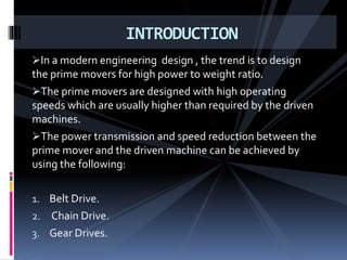
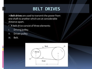
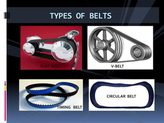

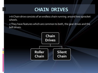
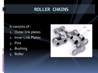
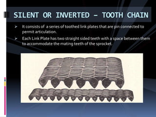
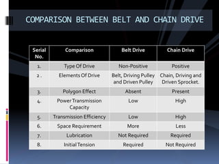
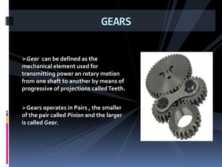
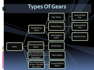
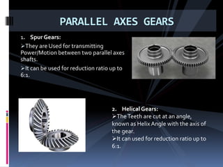
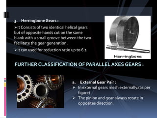
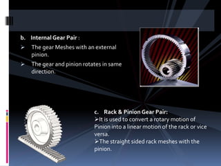
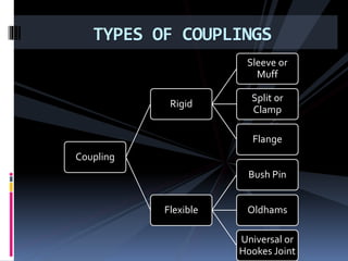
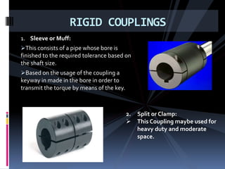
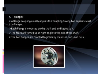
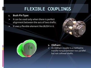


The document discusses various types of power transmission devices used to transfer motion and power between rotating shafts, including belt drives, chain drives, and gear drives. Belt drives can be flat, V-belt, timing or circular belts and are used to connect shafts over long distances. Chain drives use sprocket wheels connected by roller or silent chains. Gear drives include spur gears, helical gears, bevel gears, and worm gears to connect parallel, intersecting, or perpendicular shaft axes. Couplings like sleeve, split, flange, bush pin, and universal joints are also discussed for connecting shafts while allowing some misalignment or movement.