Download to read offline
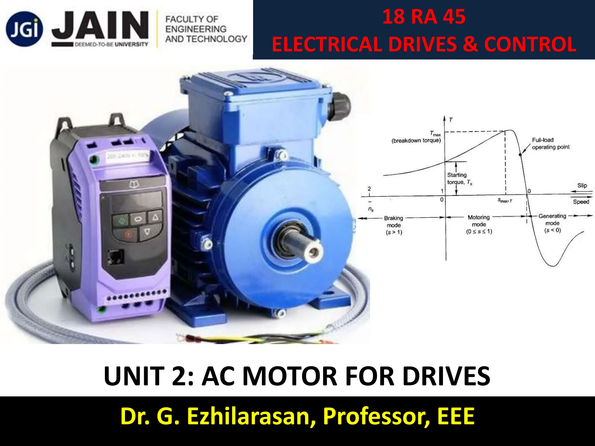
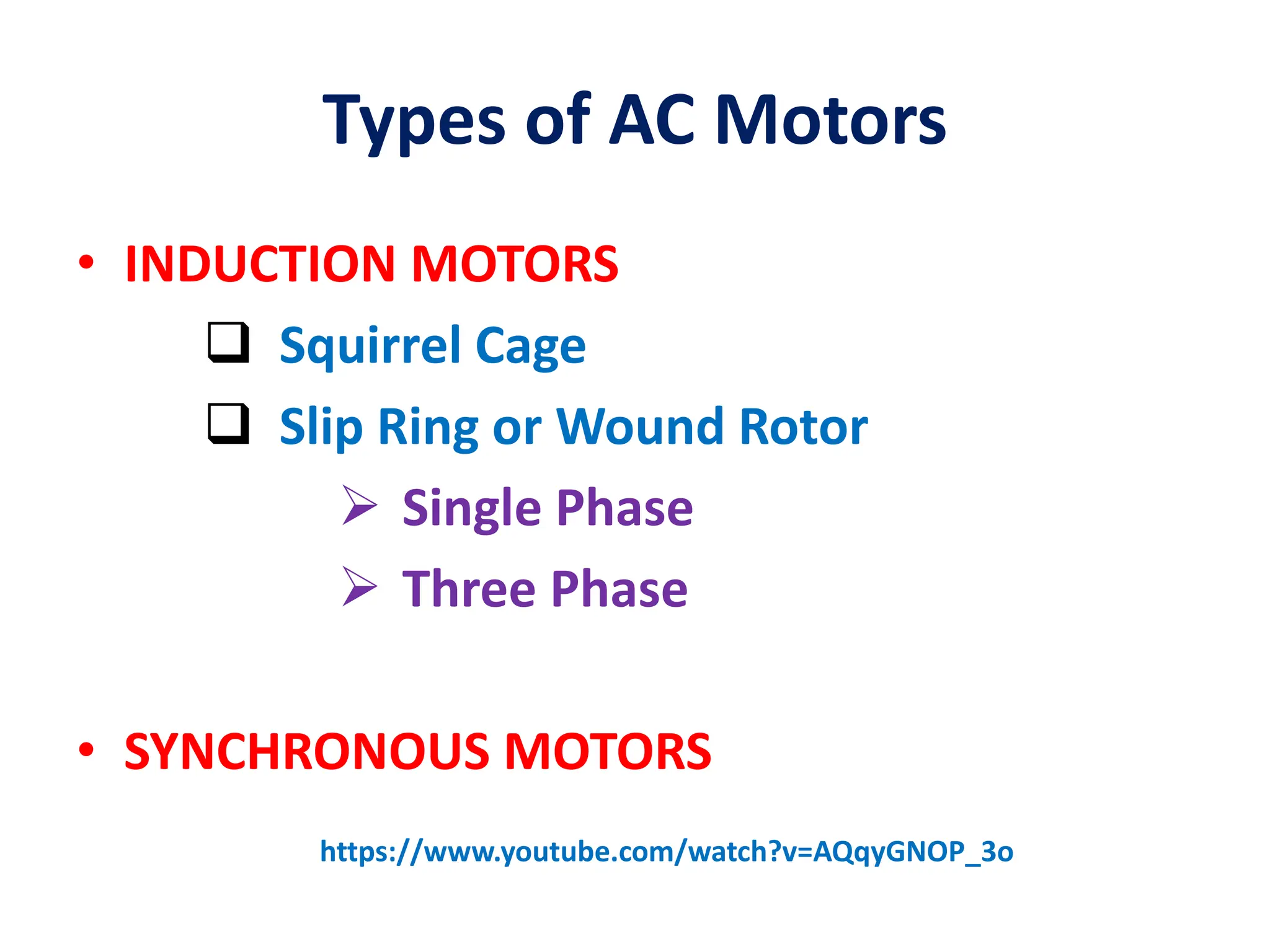
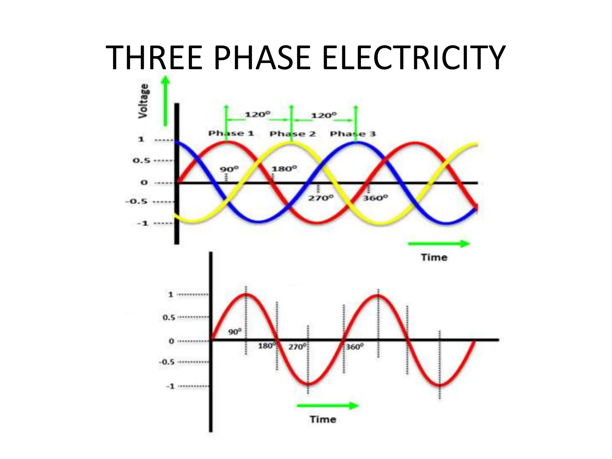
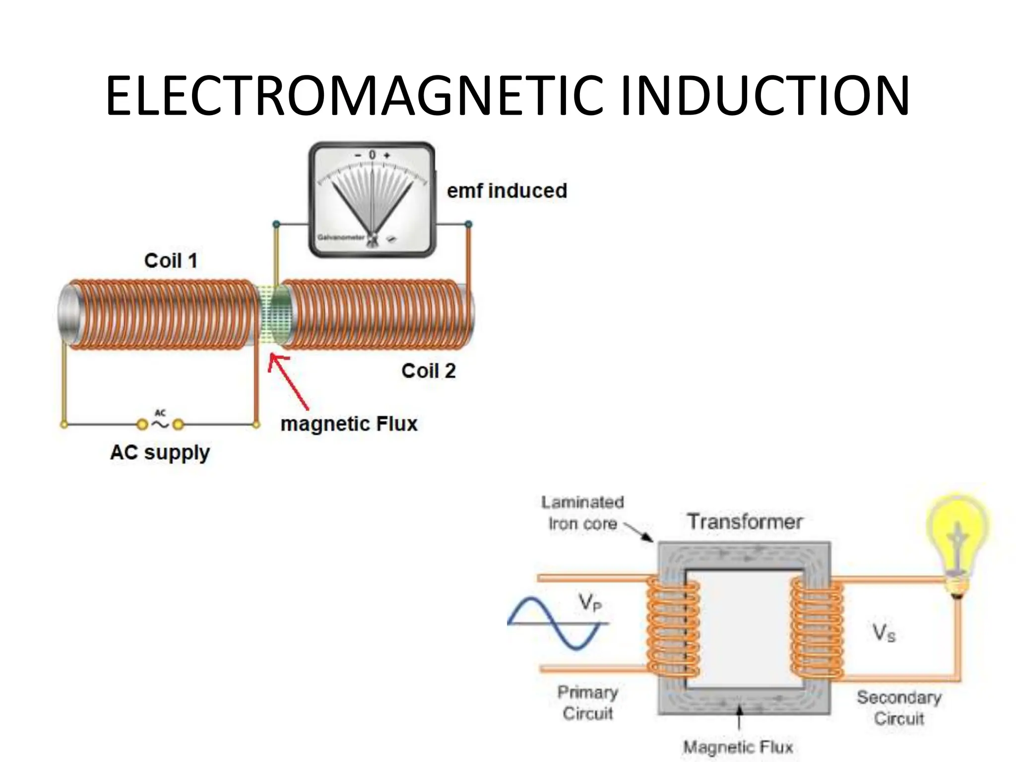
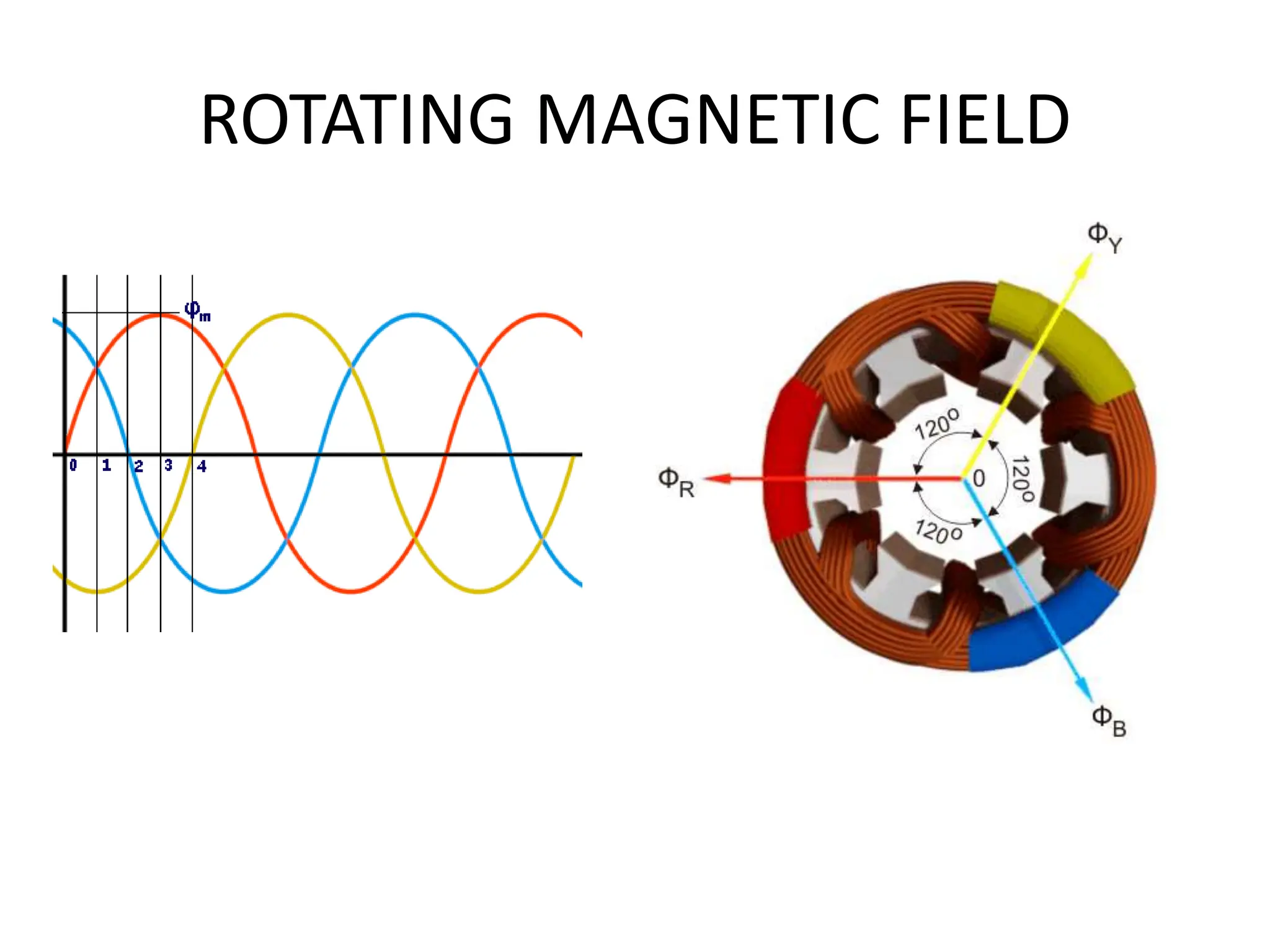
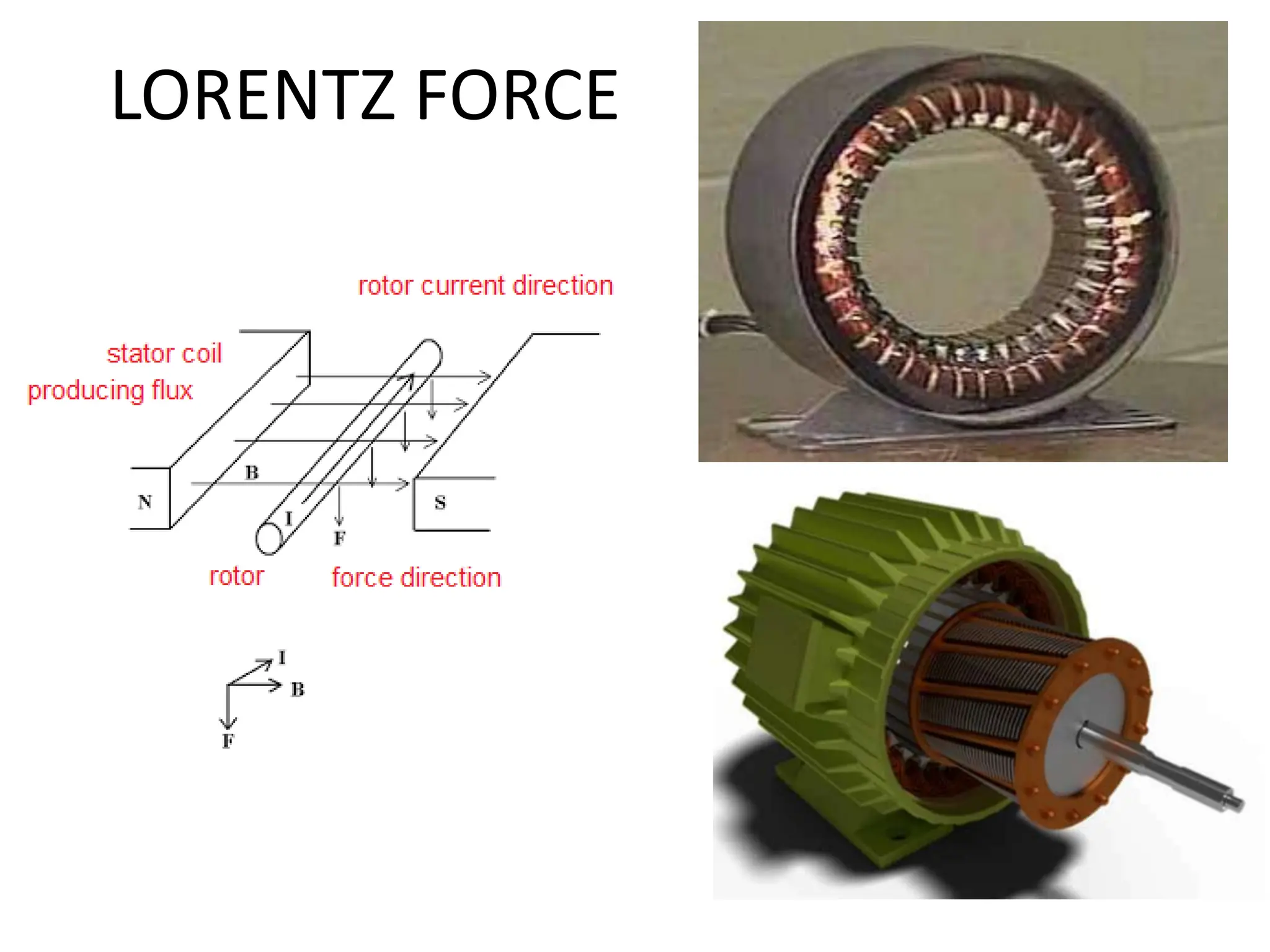
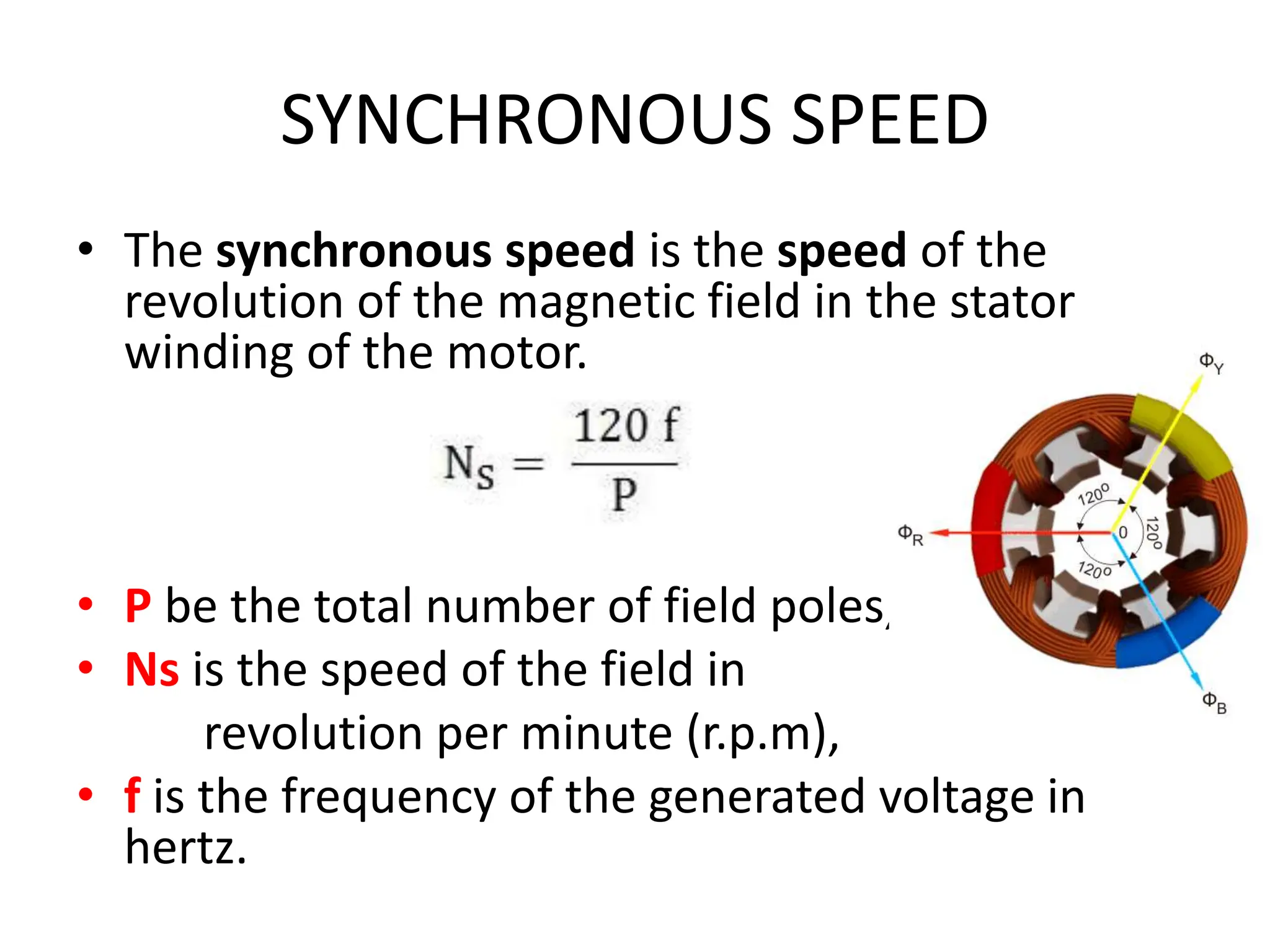
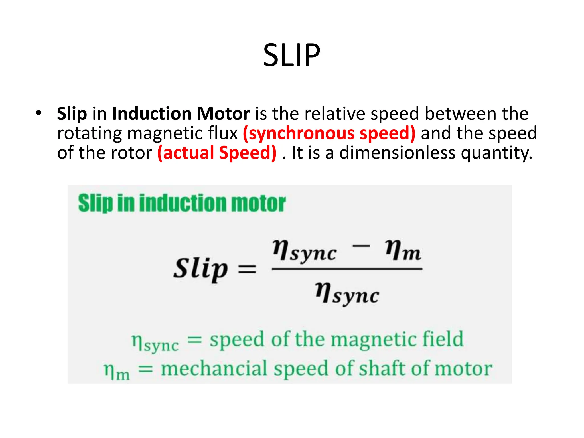
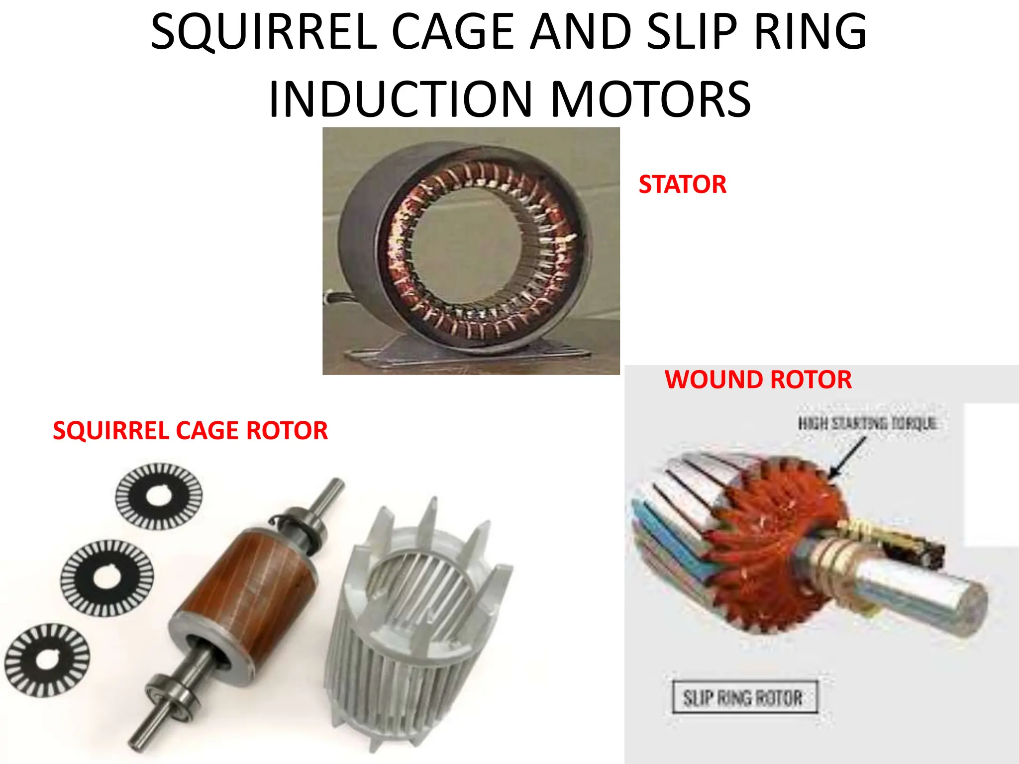
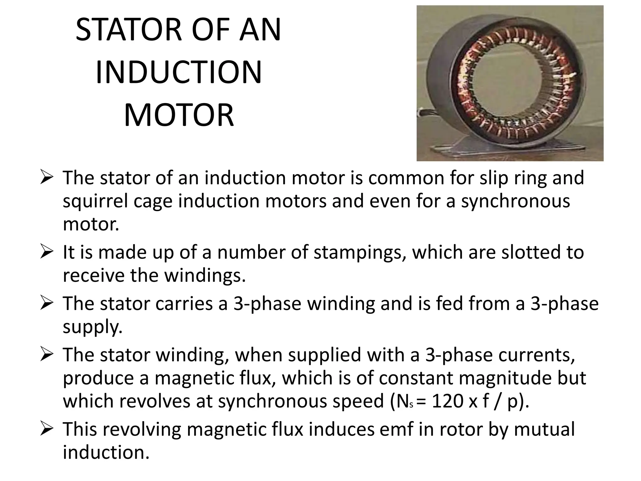
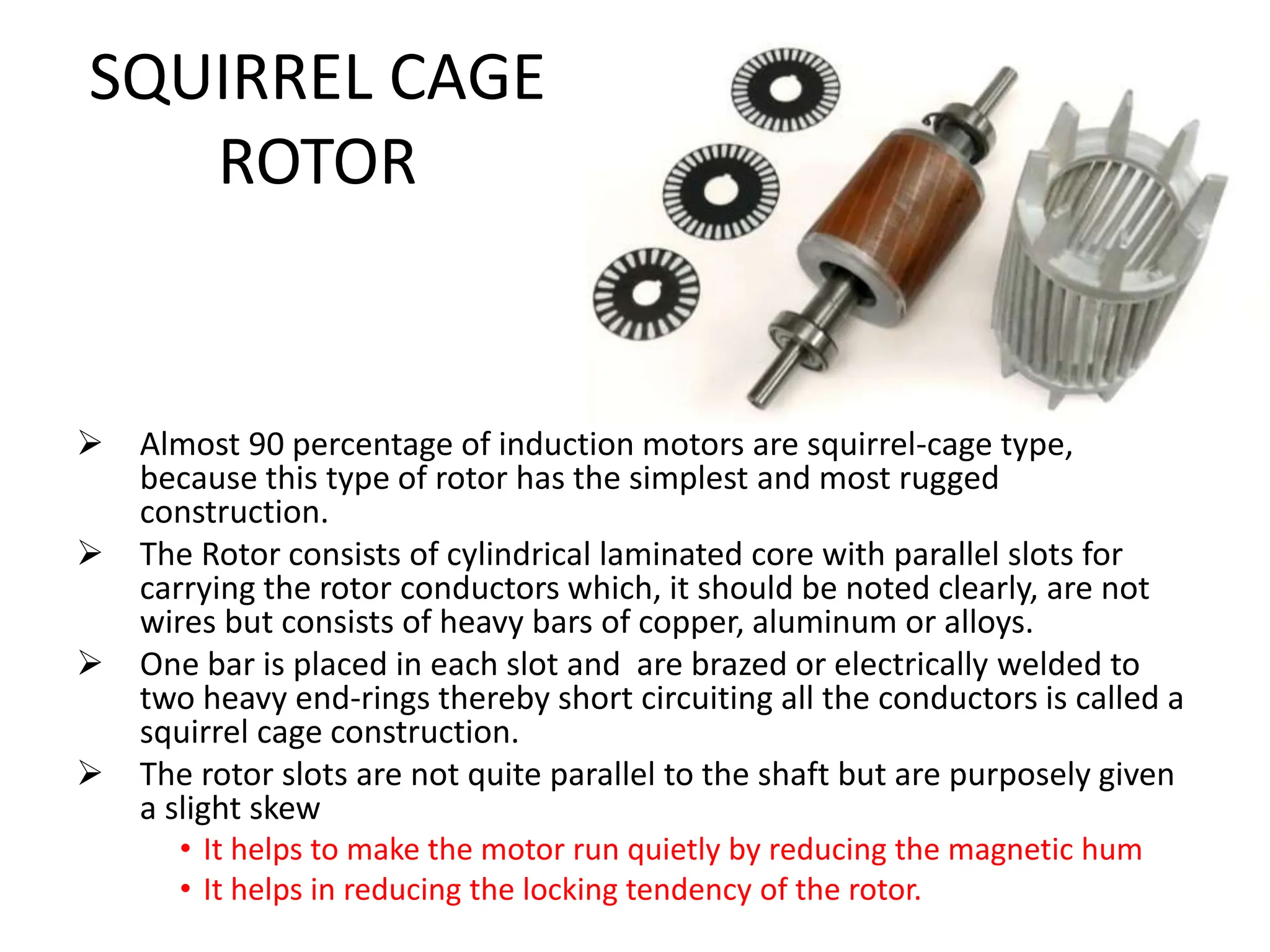
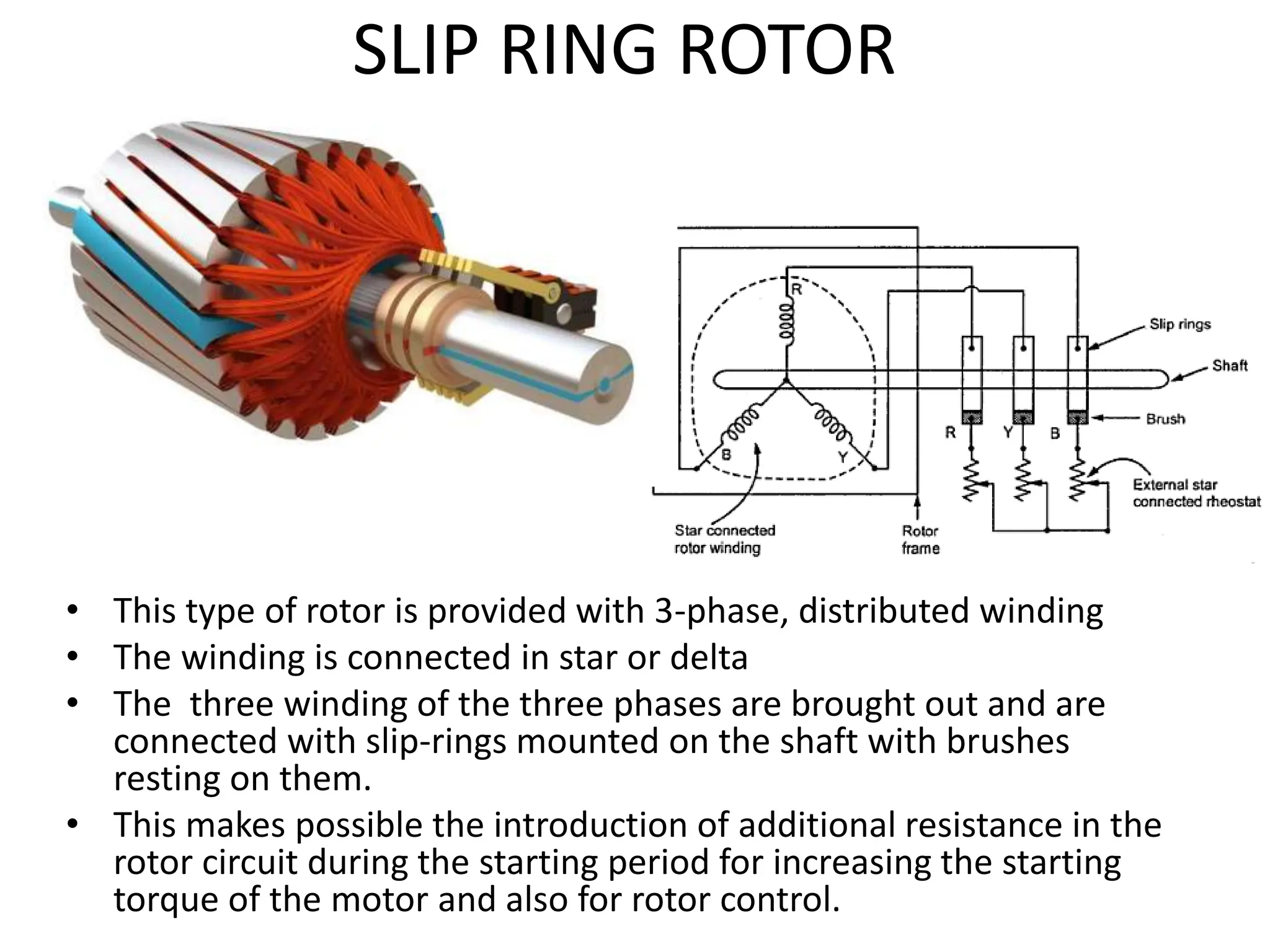
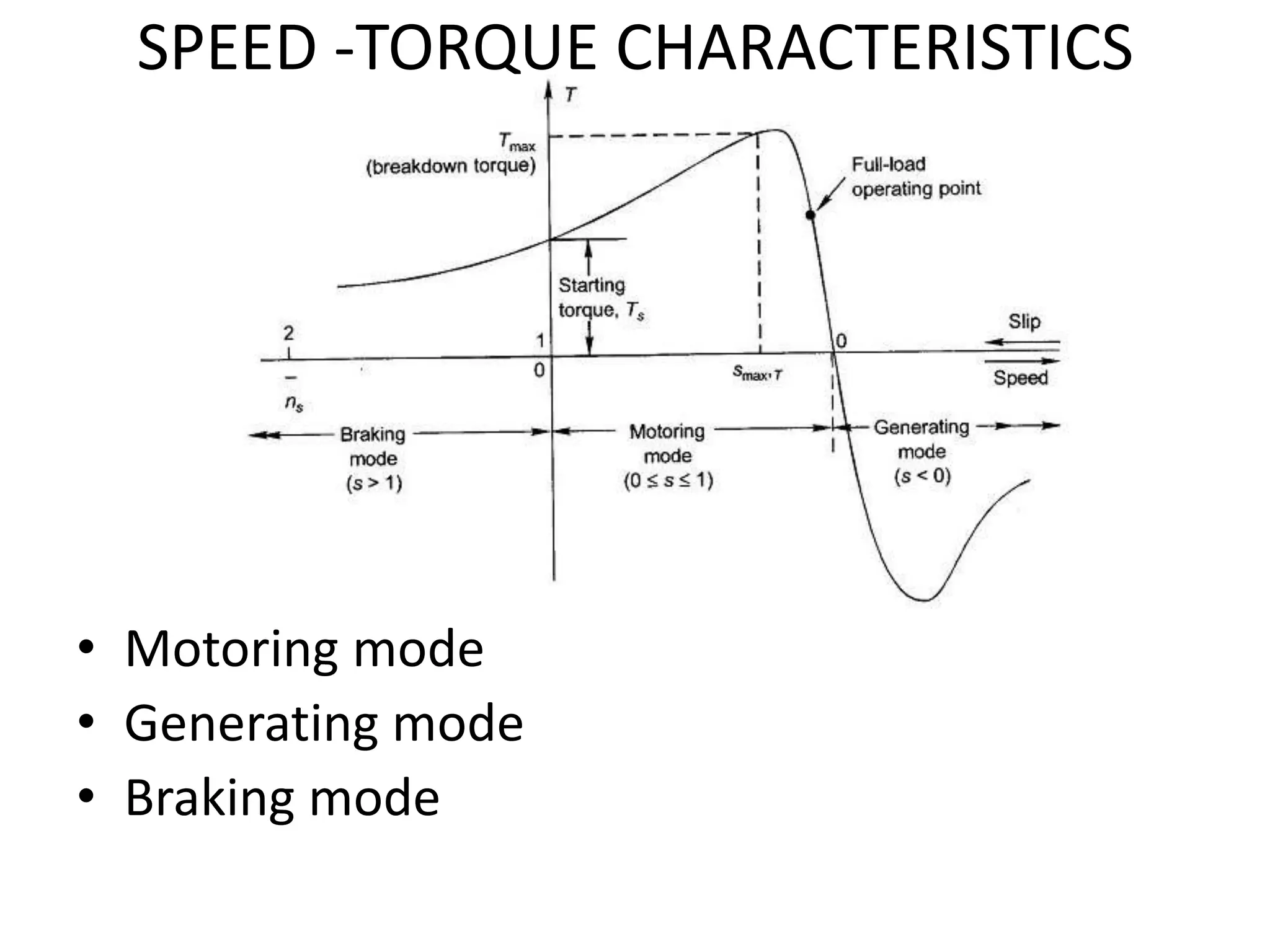
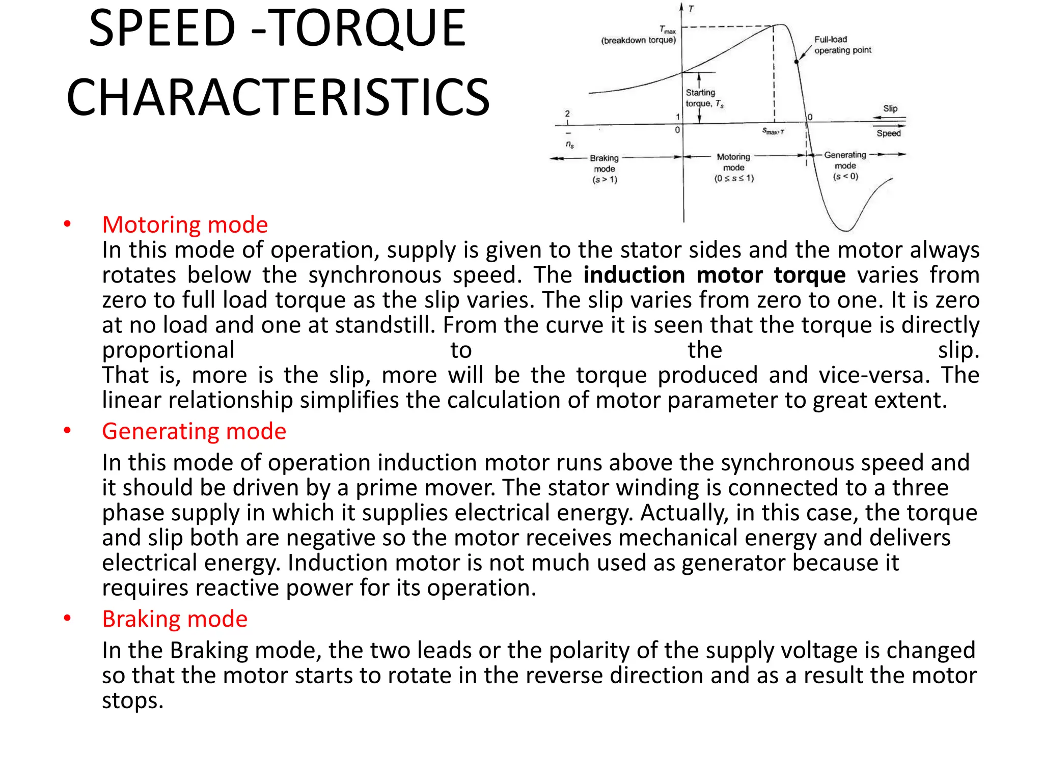

This document discusses types of AC motors including induction motors with squirrel cage and slip ring rotors, and synchronous motors. It covers the basics of AC motor operation such as three phase electricity, electromagnetic induction, rotating magnetic fields, Lorentz force, and synchronous speed. It provides details on induction motor components like the stator and different rotor types. It also explains induction motor working principles, speed-torque characteristics in motoring, generating and braking modes, and applications of universal motors.


