Download to read offline


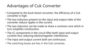
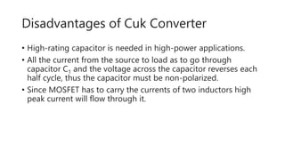

The document discusses various types of DC-DC converters, detailing the working principles, advantages, disadvantages, and applications of flyback, forward, half-bridge, full-bridge, push-pull, cuk, and sepic converters. Each type of converter has distinct characteristics, with applications ranging from power supplies for electronics to renewable energy systems. The discussion highlights the importance of component selection and efficiency in converter design.


![[IJET V2I5P8] Authors: Lakshmi K R, Kavitha Issac, Kiran Boby](https://cdn.slidesharecdn.com/ss_thumbnails/ijet-v2i5p8-161107140749-thumbnail.jpg?width=640&height=640&fit=bounds)


