Downloaded 610 times
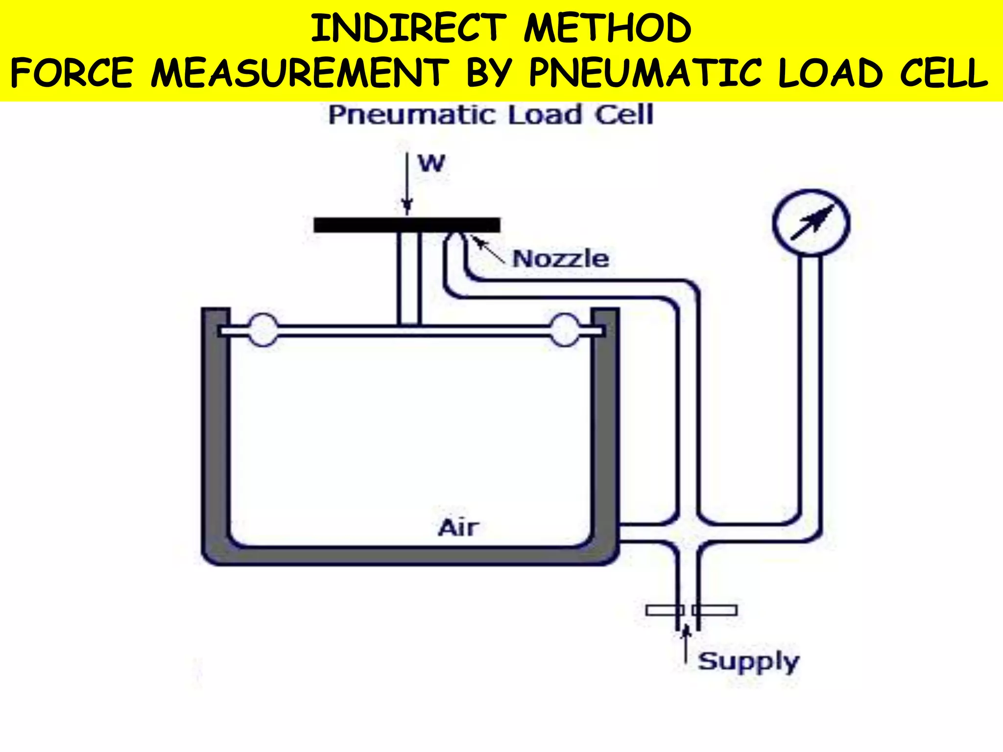
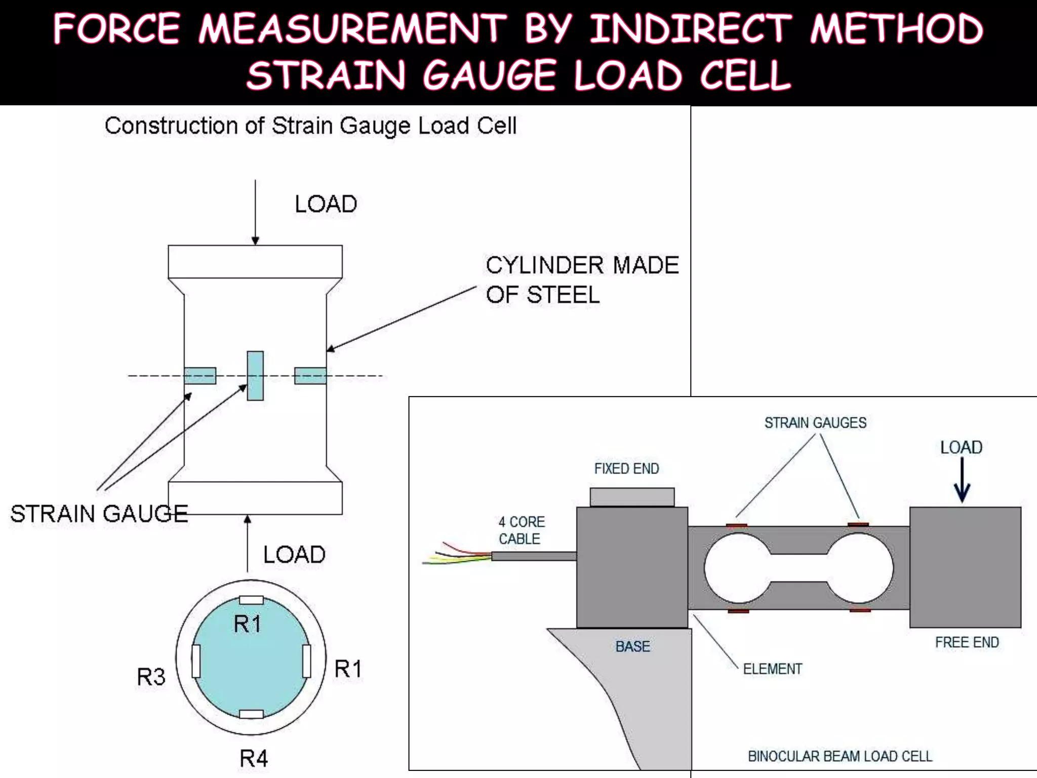
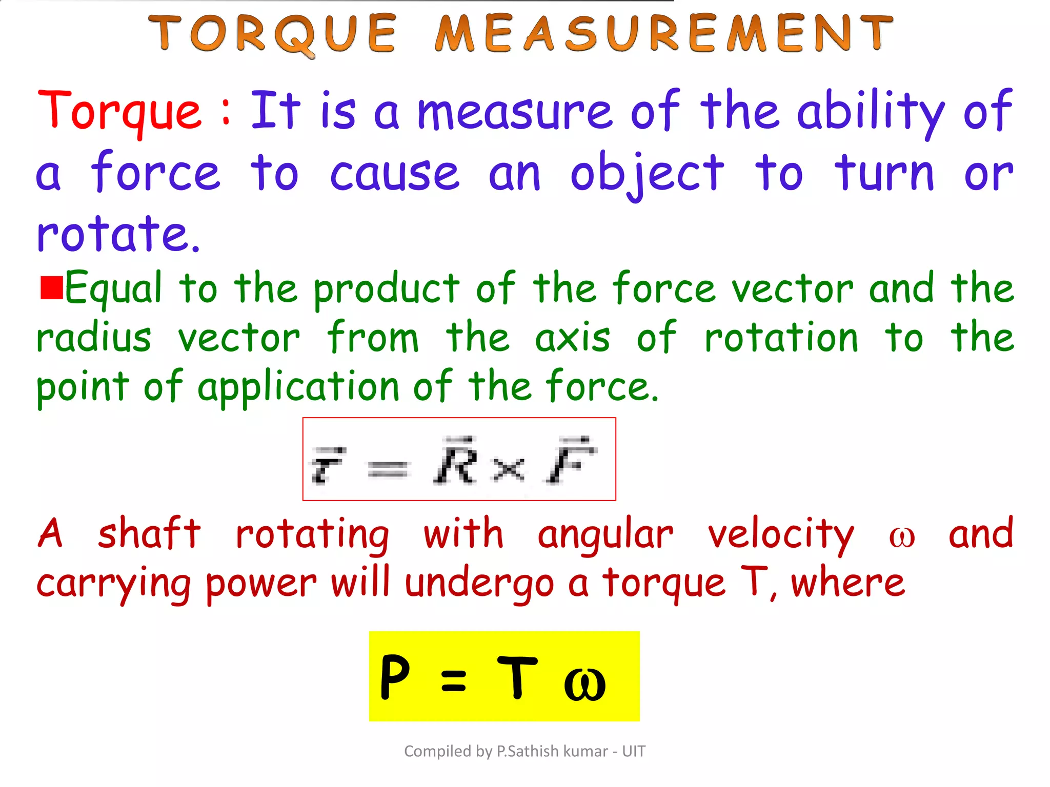
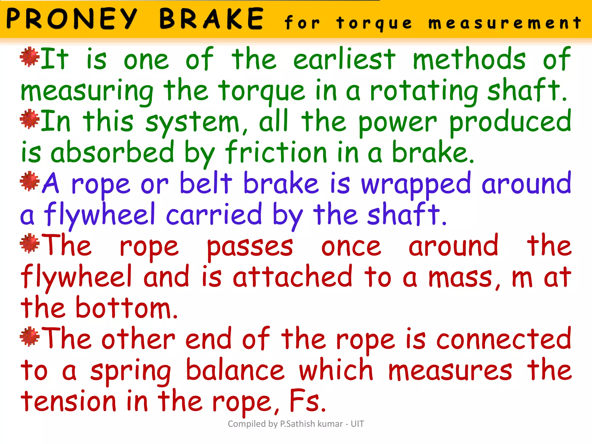
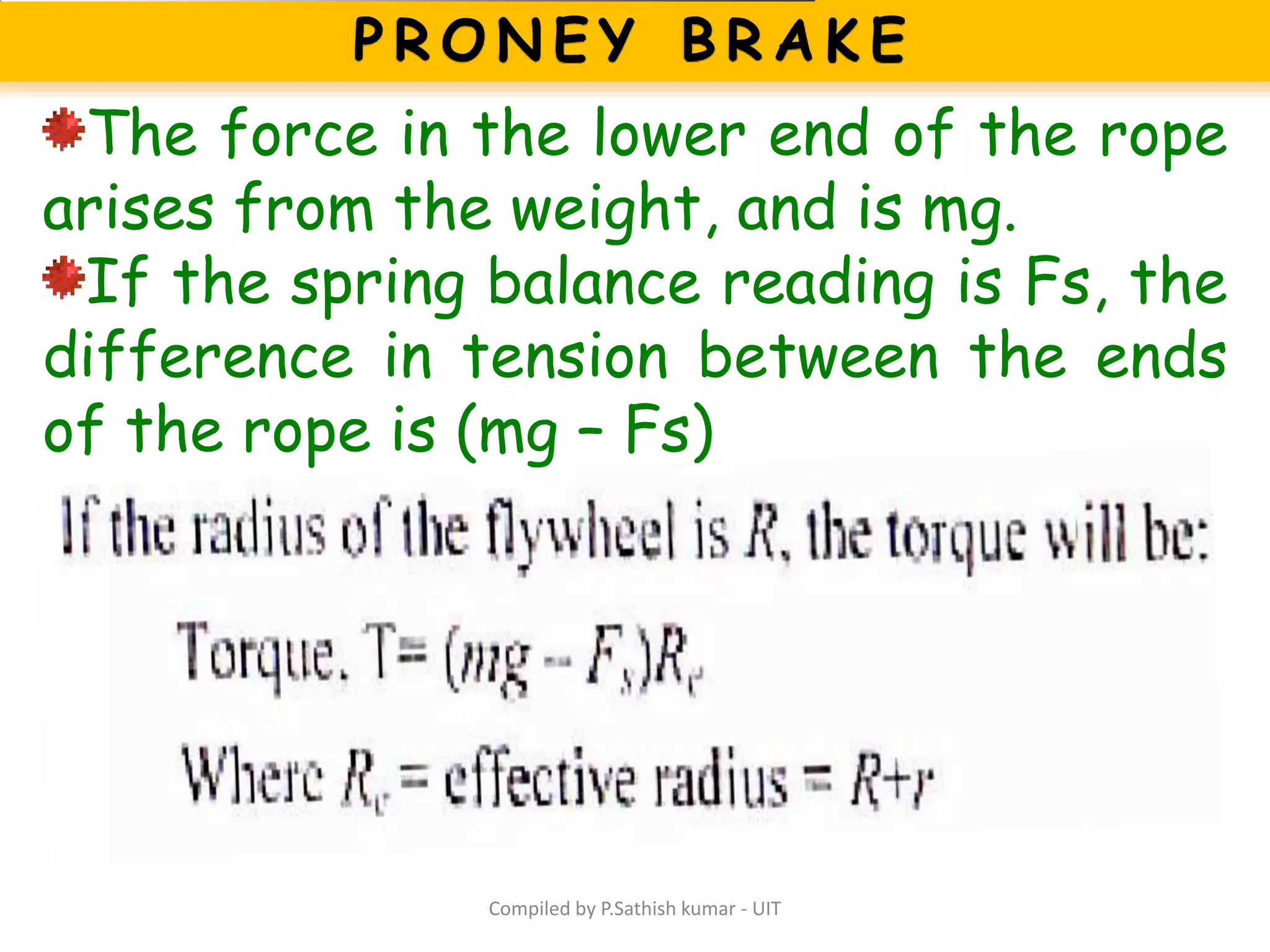
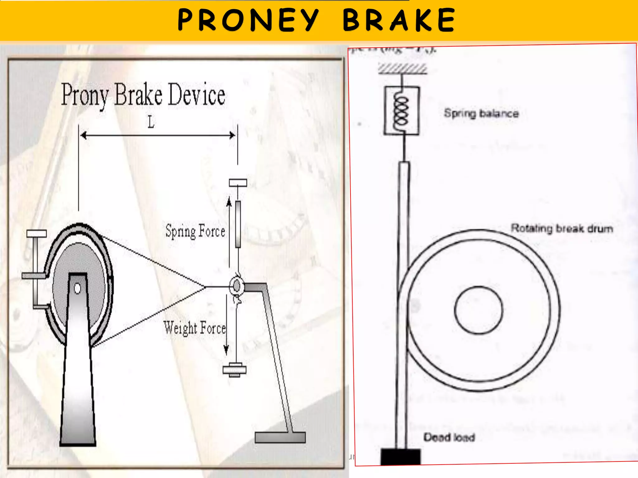
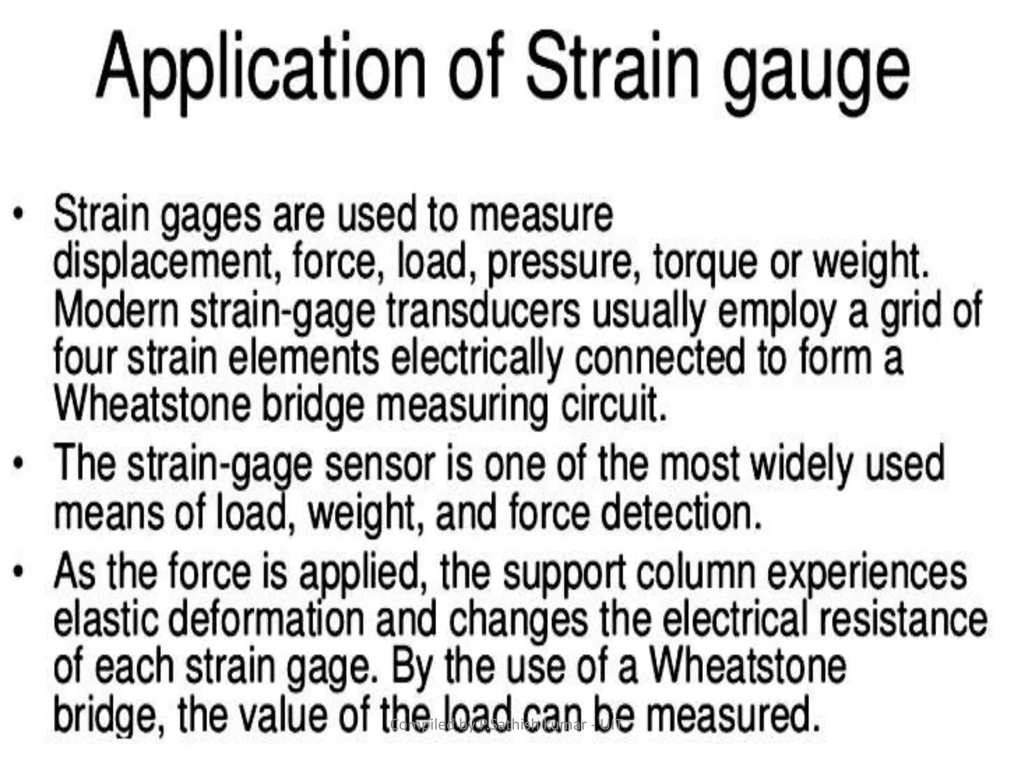
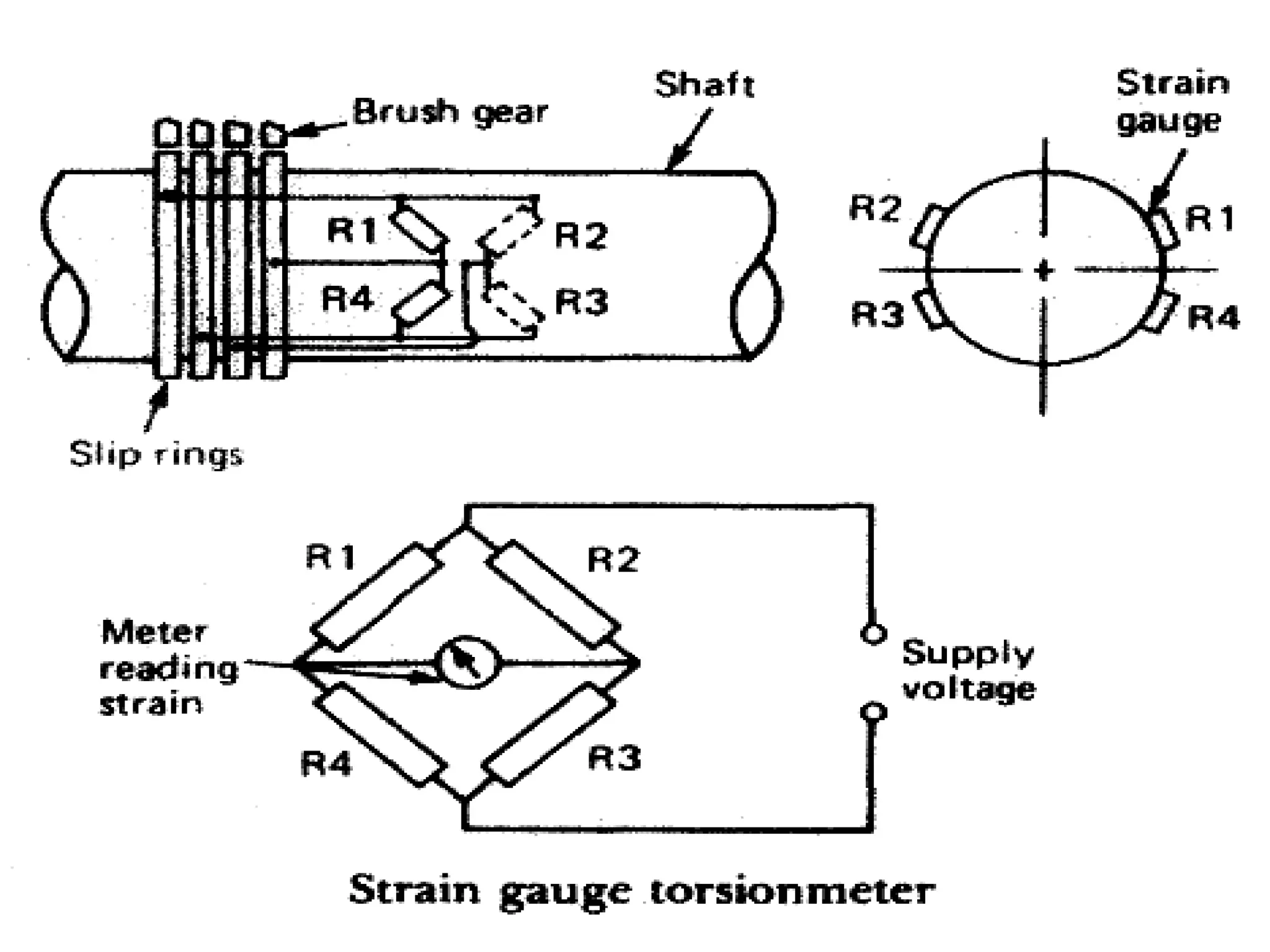
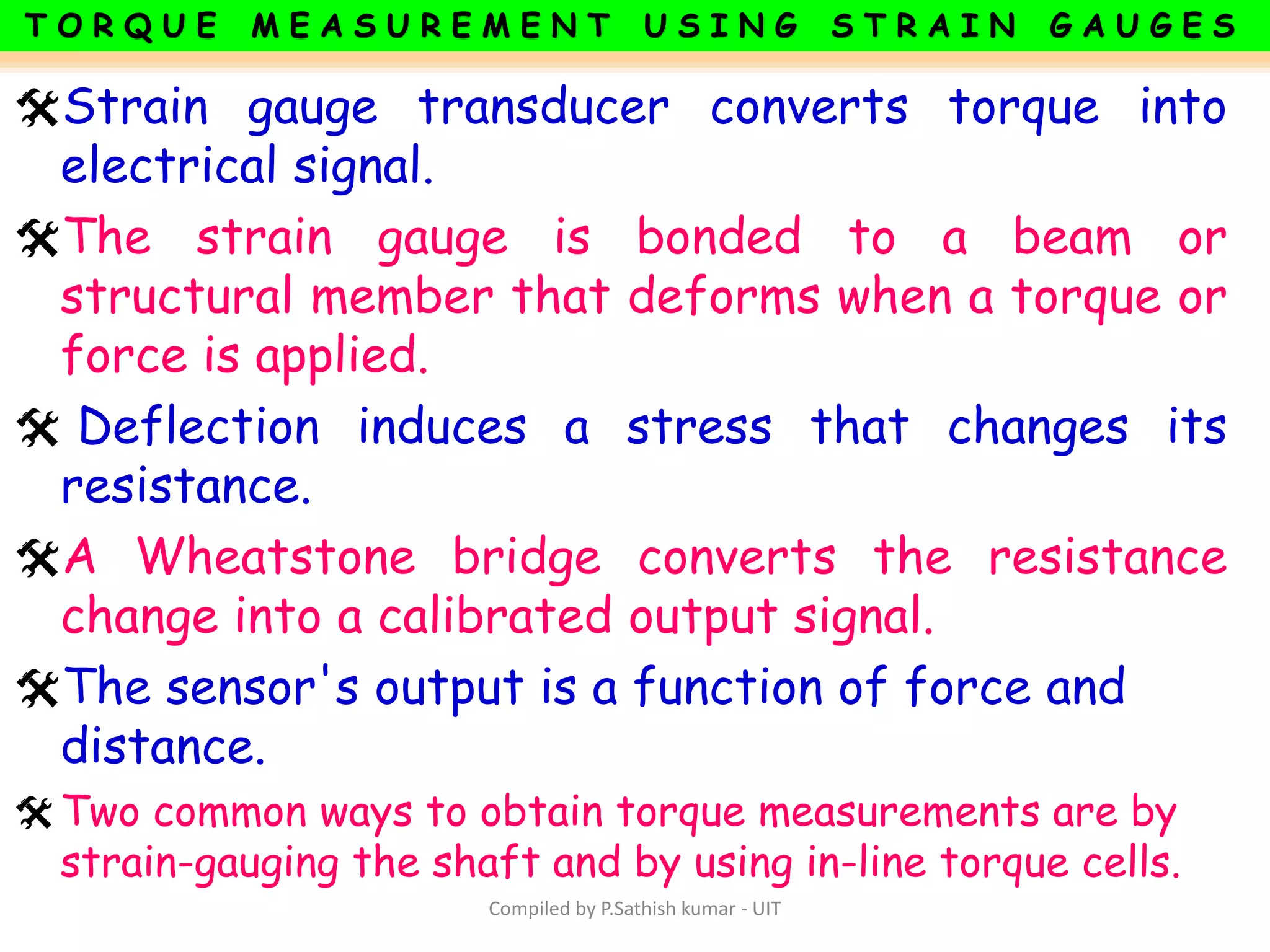

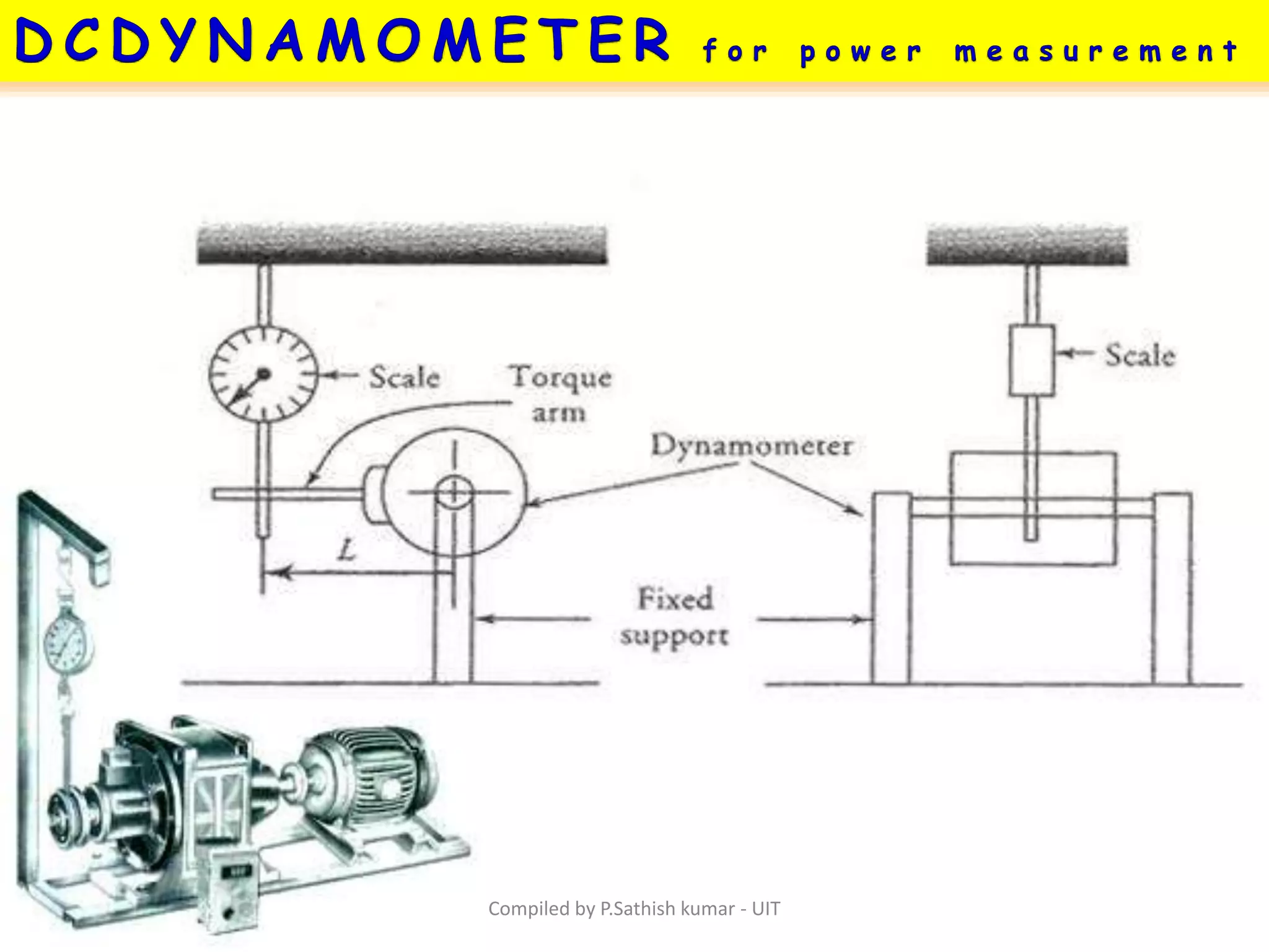

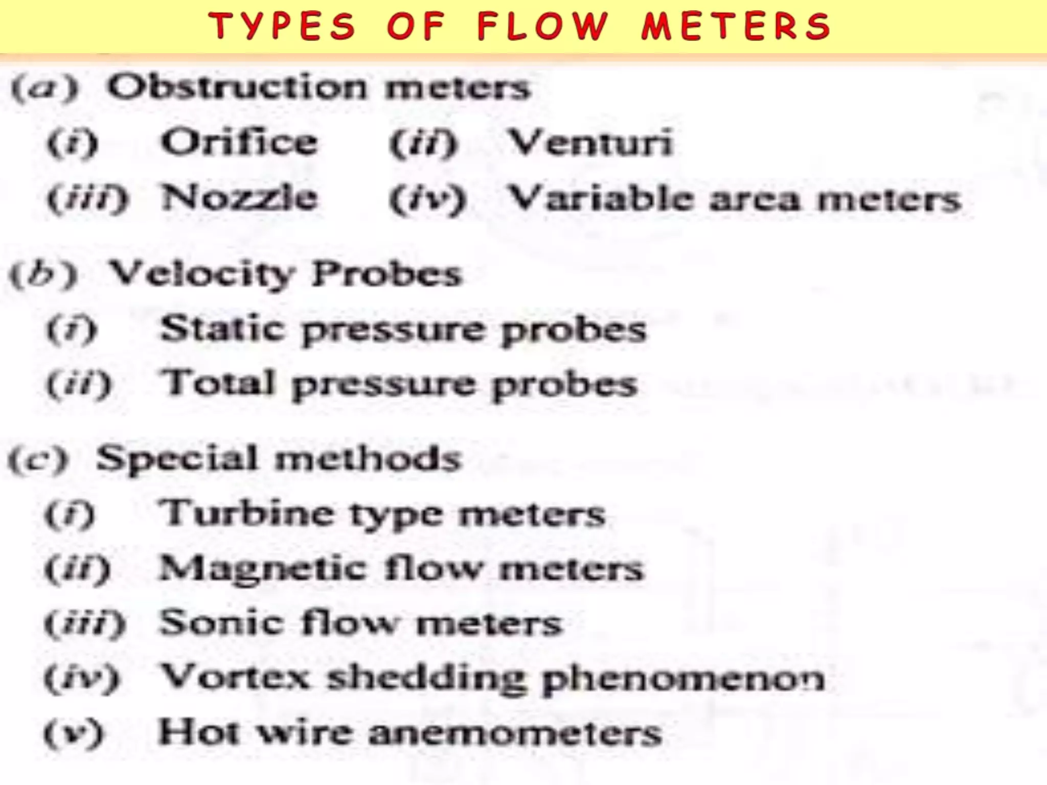
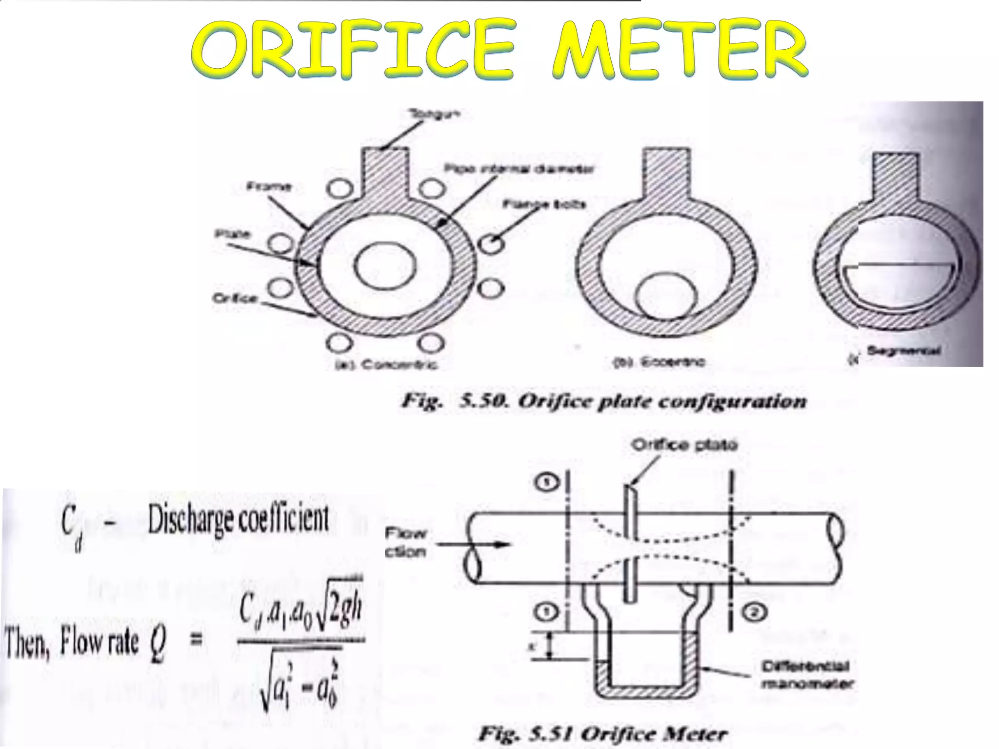
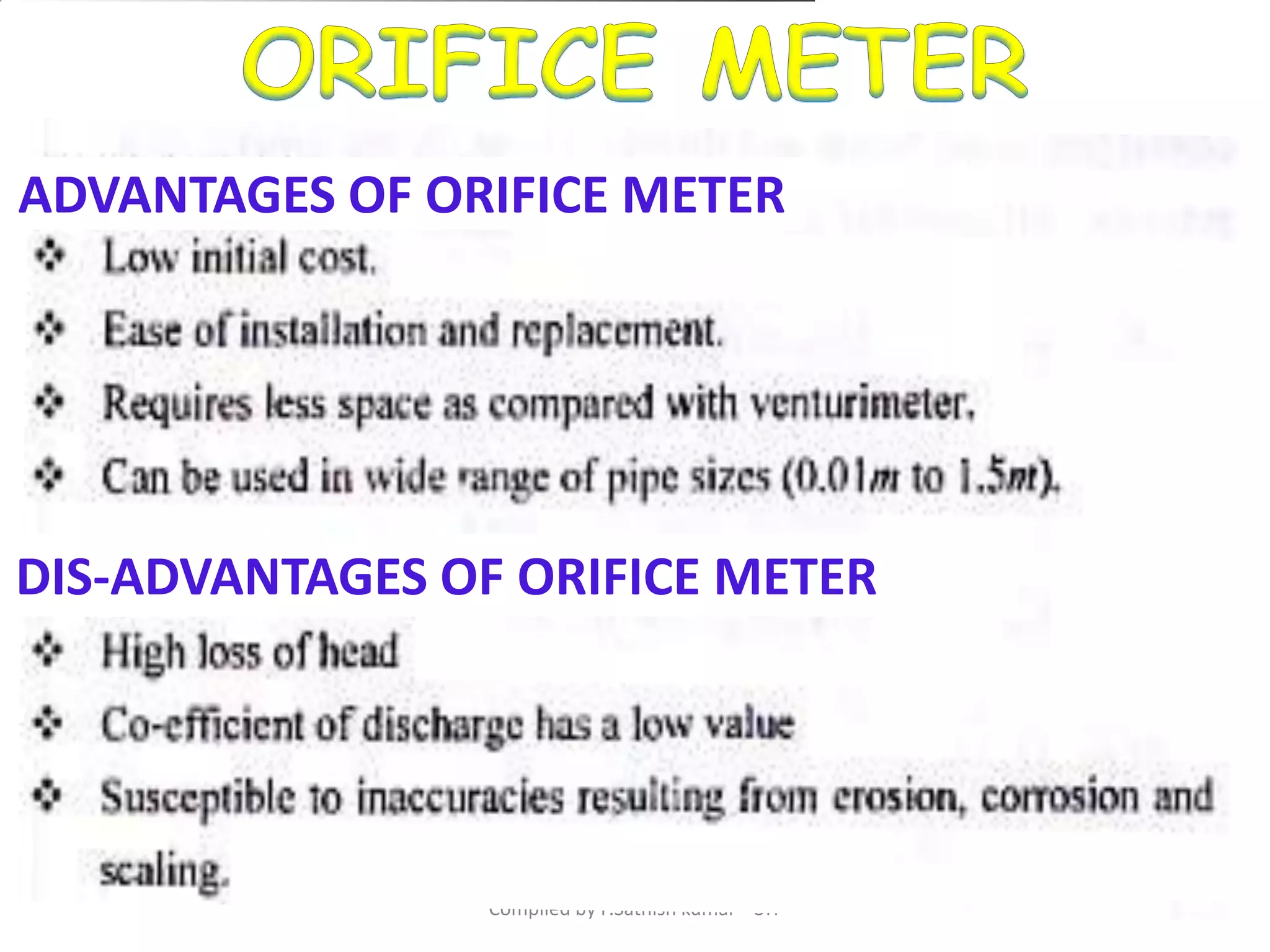

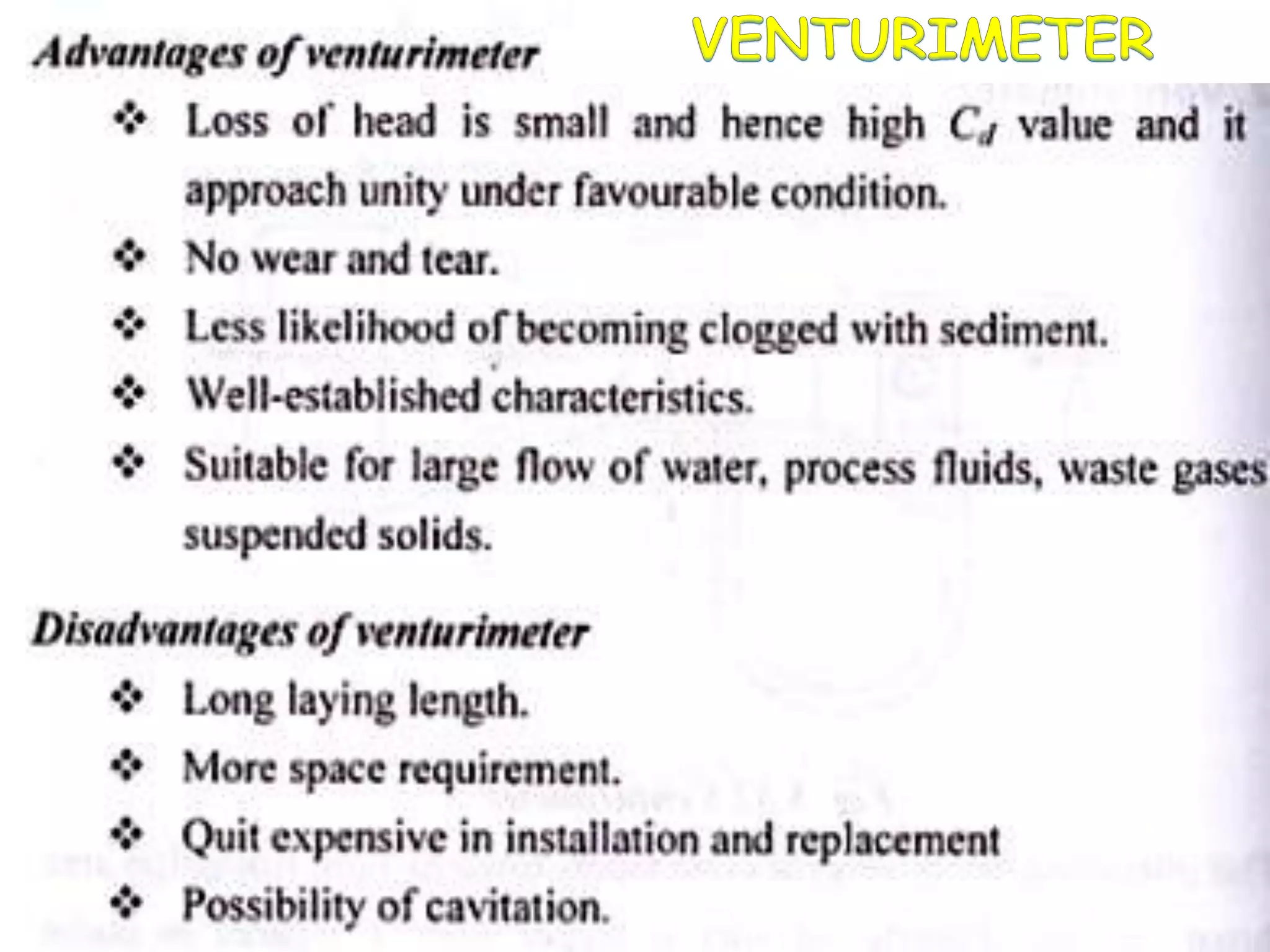

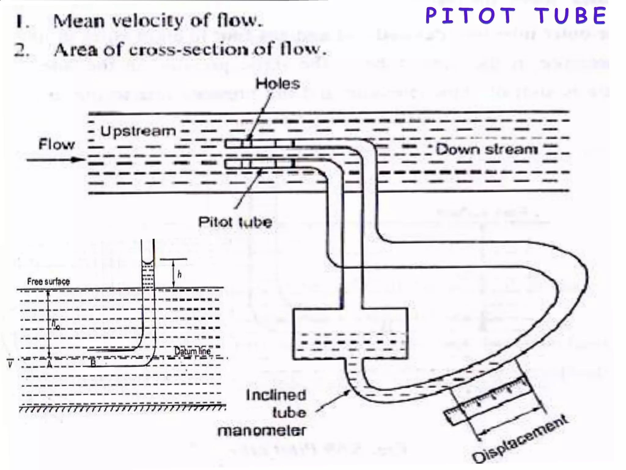
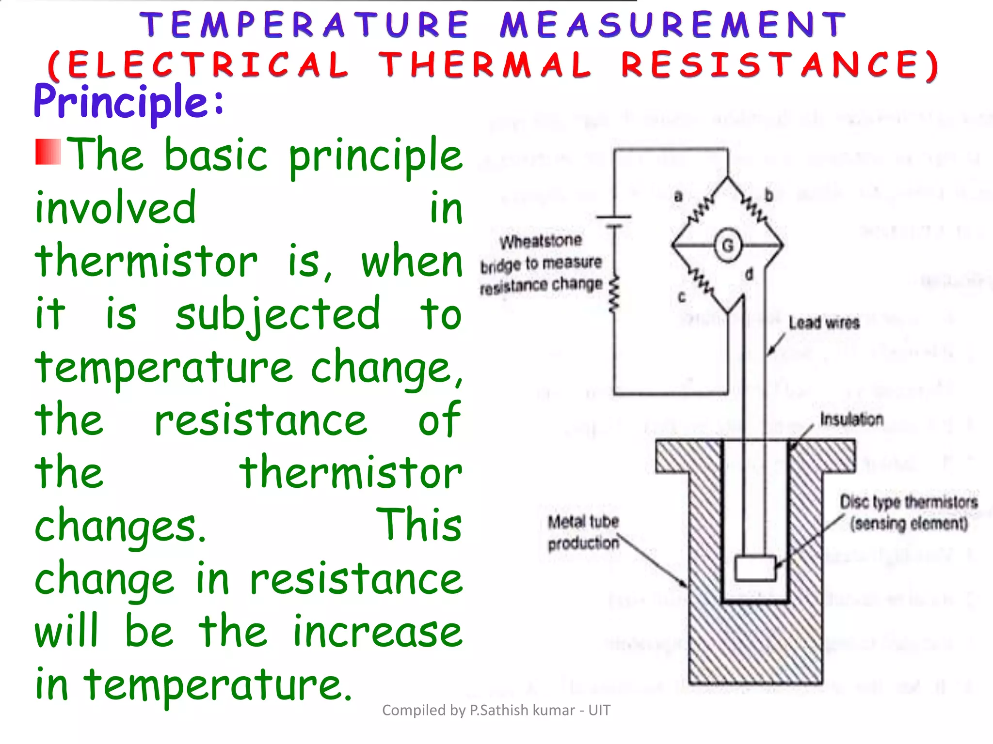
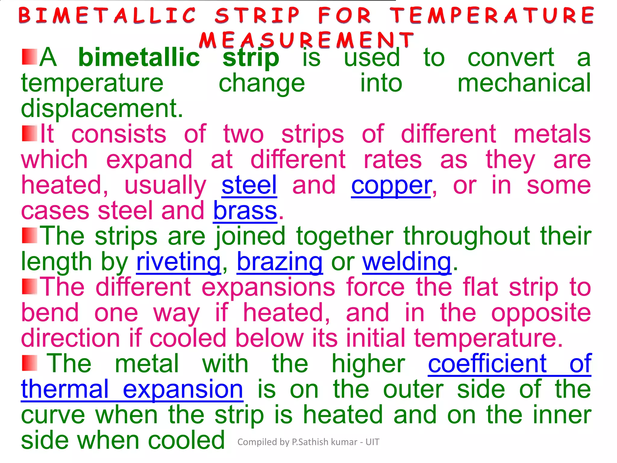
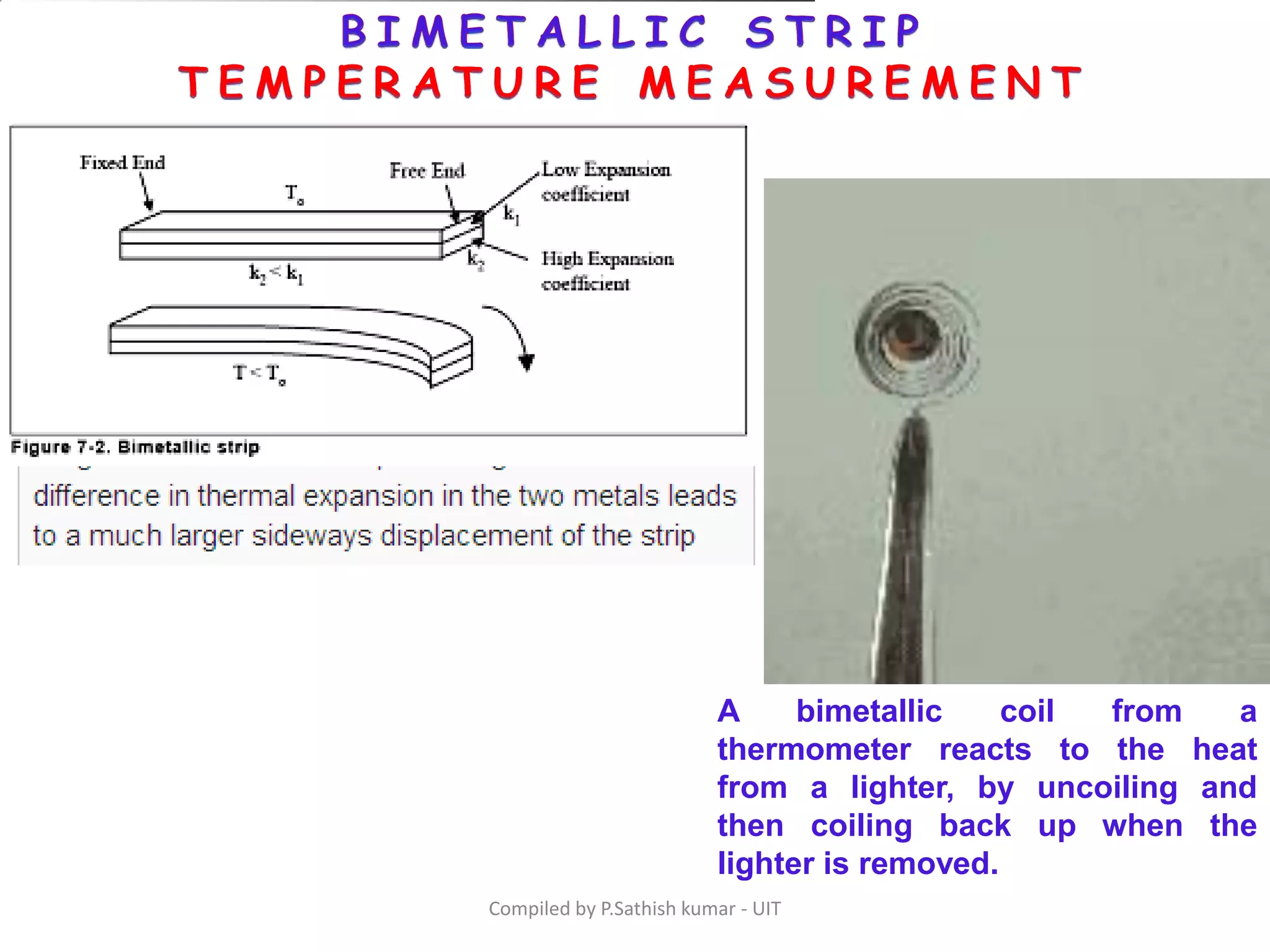
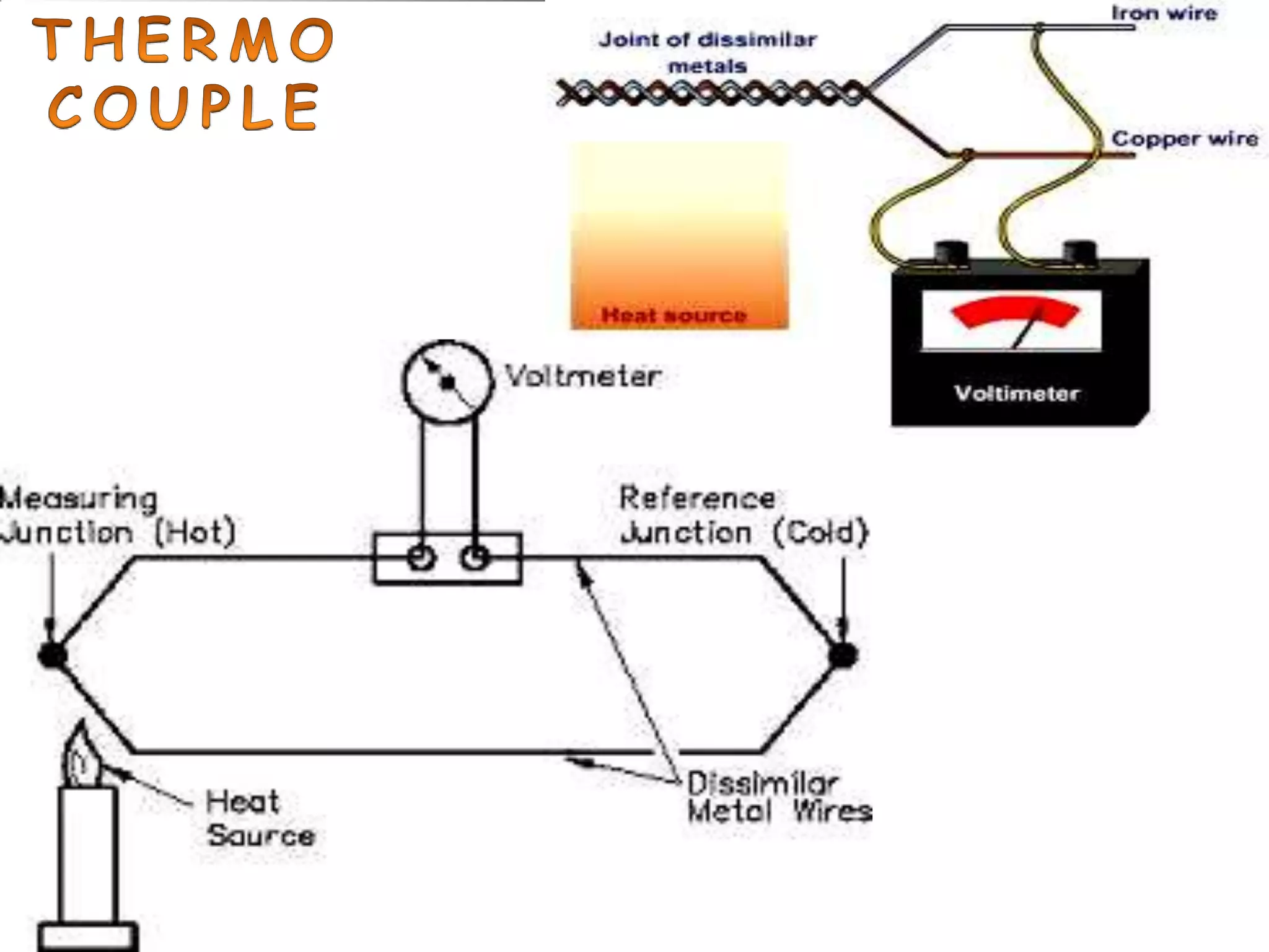


This document provides information on various methods for measuring force, torque, power, flow and temperature. It discusses direct and indirect methods for measuring force, including using spring balances, accelerometers, hydraulic load cells, pneumatic load cells and strain gauge load cells. It also describes techniques for measuring torque using rope brakes, hydraulic dynamometers and strain gauge transducers. Flow measurement is discussed for devices like venturi meters, orifice meters and rotameters. Temperature measurement techniques include bimetallic strips, thermocouples and resistance thermometers.