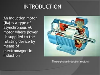
PRESENTATION
       ON
INDUCTION MOTOR


                  Naveen Sihag
                       B.Tech
Contents
1 History
2 Principle of operation and comparison to
   synchronous motors
3 Formulas
4 Construction
5 Speed control
6 Starting of induction motor
7 Types of starters
INTRODUCTION
An induction motor
(IM) is a type of
asynchronous AC
motor where power
 is supplied to the
rotating device by
means of
electromagnetic
induction
                      Three-phase induction motors
History
The induction motor with a wrapped rotor was
invented by Nikola Tesla in 1888 in the United
States. In his scientific work, Tesla laid the
foundations for understanding the way the motor
operates.
The induction motor with a cage was invented by
Mikhail Dolivo-Dobrovolsky about a year later in
Europe. Technological development in the field
has improved to where a 100 hp (73.6 kW) engine
from 1976 takes the same volume as a 7.5 hp (5.5
kW) engine did in 1897. Currently, the most
common induction motor, is the cage rotor motor.
Principle of operation
The basic difference between an induction motor and
a synchronous AC motor is that in the latter a current
is supplied onto the rotor. This then creates a
magnetic field which, through magnetic interaction,
links to the rotating magnetic field in the stator
which in turn causes the rotor to turn. It is called
synchronous because at steady state the speed of the
rotor is the same as the speed of the rotating
magnetic field in the stator.
The induction motor does not have any direct
supply onto the rotor; instead, a secondary
current is induced in the rotor. To achieve
this, stator windings are arranged around the
rotor so that when energised with a polyphase
supply they create a rotating magnetic field
pattern which sweeps past the rotor
At the moment illustrated, the current in the stator
coil is in the direction shown and increasing. The
induced voltage in the coil shown drives current and
results in a clockwise torque.
 Note that this simplified motor will turn once it is
started in motion, but has no starting torque.
Various techniques are used to produce some
asymmetry in the fields to give the motor a starting
torque.
In a three phase induction motor, the induced emf in the rotor
circuit depends on the slip of the induction motor and the
magnitude of the rotor current depends upon this induced emf
(electromotive force). When the motor is started, the slip is equal
to 1 as the rotor speed is zero, so the induced emf in the rotor is
large. As a result, a very high current flows through the rotor. This
is similar to a transformer with the secondary coil short circuited,
which causes the primary coil to draw a high current from the
mains. Similarly, when an induction motor starts, a very high
current is drawn by the stator, on the order of 5 to 9 times the full
load current. This high current can damage the motor windings
and because it causes heavy line voltage drop, other appliances
connected to the same line may be affected by the voltage
fluctuation. To avoid such effects, the starting current should be
limited
The rotational speed of the rotor is controlled by the number of
pole pairs (number of windings in the stator) and by the frequency
of the supply voltage. Before the development of cheap power
electronics, it was difficult to vary the frequency to the motor and
therefore the uses for the induction motor were limited. There are
various techniques to produce a desired speed. The most
commonly used technique is PWM(Pulse Width Modulation), in
which a DC signal is switched on and off very rapidly, producing a
sequence of electrical pulses to the inductor windings. The
dutycycle of the pulses, also known as the mark-space ratio,
determines the average power input to the motor.
TYPES OF MOTORS
   Based on type of phase supply
      ○   Three phase induction motor (self starting
          in nature)
     single phase induction motor (not self
       starting)
   Other
     Squirrel cage induction motor
   Slip ring induction motor
The rotor bars in squirrel-cage induction motors
are not straight, but have some skew to reduce
noise and harmonics.
The motor's phase type is one of two types


1. Single-phase induction motor

2. 3-phase induction motor
In a DC machine, the stator winding is excited by DC
current and hence the field produced by this
winding is time invariant in nature. In this machine the
conversion of energy from electrical to mechanical form or
vice versa is possible by one of the following ways:

1.rotating the rotor in the field produced by the stator
2.feeding external dc current through carbon brushes to
the rotor
Electric motors convert electrical power to mechanical
power in its rotor (rotating part).


There are several ways to supply power to the rotor.
AC motor this power is induced in the rotating device.
 An induction motor can be called a rotating
transformer
  because the stator(stationary part) is essentially
  the primary side of the transformer and the rotor
  (rotating part) is the secondary side.
Induction motors are widely used, especially polyphase
induction motors, which are frequently used in industrial
drives.
Construction
 The stator consists of wound 'poles' that carry the
supply current that induces a magnetic field in the
conductor. The number of 'poles' can vary between
motor types but the poles are always in (i.e. 2,4,6 etc)
pairs. There are two types of rotor
             1.Squirrel-cage rotor
               2.Slip ring rotor

The most common rotor is a squirrel-cage rotor. It is
made up of bars of either solid copper (most common)
or aluminum that span the length of the rotor, and are
connected through a ring at each end
Slip Ring Rotor


Resistance-start ac induction motor.
Formulas
The relationship between the supply frequency, f, the
number of pole pairs, p, and the synchronous speed, n,
is given by f = p*n.
From this relationship:
Speed of rotating field (n) = f/P (revs.s-1)
Speed of rotor = n(1-S) (rev.s-1)
where S is the slip.
Slip is calculated using:
% slip = (n - r) / n * 100
where r is the rotor speed
In contrast, a synchronous motor always runs at either a
constant speed N=(120f)/P or zero.
3phase induction motor

3phase induction motor

  • 1.
    PRESENTATION ON INDUCTION MOTOR Naveen Sihag B.Tech
  • 2.
    Contents 1 History 2 Principleof operation and comparison to synchronous motors 3 Formulas 4 Construction 5 Speed control 6 Starting of induction motor 7 Types of starters
  • 3.
    INTRODUCTION An induction motor (IM)is a type of asynchronous AC motor where power is supplied to the rotating device by means of electromagnetic induction Three-phase induction motors
  • 4.
    History The induction motorwith a wrapped rotor was invented by Nikola Tesla in 1888 in the United States. In his scientific work, Tesla laid the foundations for understanding the way the motor operates. The induction motor with a cage was invented by Mikhail Dolivo-Dobrovolsky about a year later in Europe. Technological development in the field has improved to where a 100 hp (73.6 kW) engine from 1976 takes the same volume as a 7.5 hp (5.5 kW) engine did in 1897. Currently, the most common induction motor, is the cage rotor motor.
  • 5.
    Principle of operation Thebasic difference between an induction motor and a synchronous AC motor is that in the latter a current is supplied onto the rotor. This then creates a magnetic field which, through magnetic interaction, links to the rotating magnetic field in the stator which in turn causes the rotor to turn. It is called synchronous because at steady state the speed of the rotor is the same as the speed of the rotating magnetic field in the stator.
  • 6.
    The induction motordoes not have any direct supply onto the rotor; instead, a secondary current is induced in the rotor. To achieve this, stator windings are arranged around the rotor so that when energised with a polyphase supply they create a rotating magnetic field pattern which sweeps past the rotor
  • 7.
    At the momentillustrated, the current in the stator coil is in the direction shown and increasing. The induced voltage in the coil shown drives current and results in a clockwise torque. Note that this simplified motor will turn once it is started in motion, but has no starting torque. Various techniques are used to produce some asymmetry in the fields to give the motor a starting torque.
  • 8.
    In a threephase induction motor, the induced emf in the rotor circuit depends on the slip of the induction motor and the magnitude of the rotor current depends upon this induced emf (electromotive force). When the motor is started, the slip is equal to 1 as the rotor speed is zero, so the induced emf in the rotor is large. As a result, a very high current flows through the rotor. This is similar to a transformer with the secondary coil short circuited, which causes the primary coil to draw a high current from the mains. Similarly, when an induction motor starts, a very high current is drawn by the stator, on the order of 5 to 9 times the full load current. This high current can damage the motor windings and because it causes heavy line voltage drop, other appliances connected to the same line may be affected by the voltage fluctuation. To avoid such effects, the starting current should be limited
  • 9.
    The rotational speedof the rotor is controlled by the number of pole pairs (number of windings in the stator) and by the frequency of the supply voltage. Before the development of cheap power electronics, it was difficult to vary the frequency to the motor and therefore the uses for the induction motor were limited. There are various techniques to produce a desired speed. The most commonly used technique is PWM(Pulse Width Modulation), in which a DC signal is switched on and off very rapidly, producing a sequence of electrical pulses to the inductor windings. The dutycycle of the pulses, also known as the mark-space ratio, determines the average power input to the motor.
  • 10.
    TYPES OF MOTORS  Based on type of phase supply ○ Three phase induction motor (self starting in nature)  single phase induction motor (not self starting)  Other  Squirrel cage induction motor  Slip ring induction motor
  • 11.
    The rotor barsin squirrel-cage induction motors are not straight, but have some skew to reduce noise and harmonics. The motor's phase type is one of two types 1. Single-phase induction motor 2. 3-phase induction motor
  • 12.
    In a DCmachine, the stator winding is excited by DC current and hence the field produced by this winding is time invariant in nature. In this machine the conversion of energy from electrical to mechanical form or vice versa is possible by one of the following ways: 1.rotating the rotor in the field produced by the stator 2.feeding external dc current through carbon brushes to the rotor
  • 13.
    Electric motors convertelectrical power to mechanical power in its rotor (rotating part). There are several ways to supply power to the rotor. AC motor this power is induced in the rotating device. An induction motor can be called a rotating transformer because the stator(stationary part) is essentially the primary side of the transformer and the rotor (rotating part) is the secondary side. Induction motors are widely used, especially polyphase induction motors, which are frequently used in industrial drives.
  • 14.
    Construction The statorconsists of wound 'poles' that carry the supply current that induces a magnetic field in the conductor. The number of 'poles' can vary between motor types but the poles are always in (i.e. 2,4,6 etc) pairs. There are two types of rotor 1.Squirrel-cage rotor 2.Slip ring rotor The most common rotor is a squirrel-cage rotor. It is made up of bars of either solid copper (most common) or aluminum that span the length of the rotor, and are connected through a ring at each end
  • 15.
  • 16.
    Formulas The relationship betweenthe supply frequency, f, the number of pole pairs, p, and the synchronous speed, n, is given by f = p*n. From this relationship: Speed of rotating field (n) = f/P (revs.s-1) Speed of rotor = n(1-S) (rev.s-1) where S is the slip. Slip is calculated using: % slip = (n - r) / n * 100 where r is the rotor speed In contrast, a synchronous motor always runs at either a constant speed N=(120f)/P or zero.