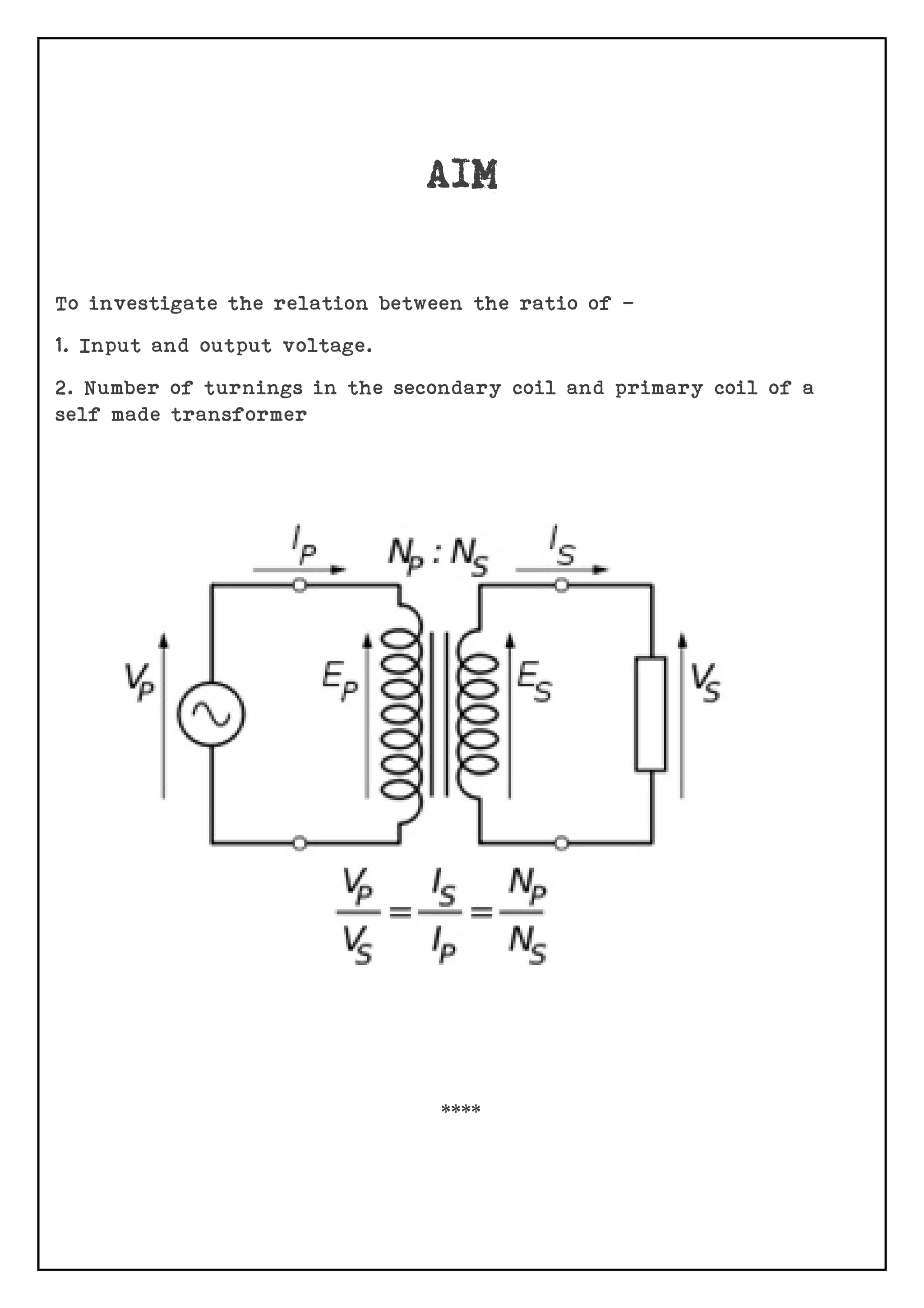
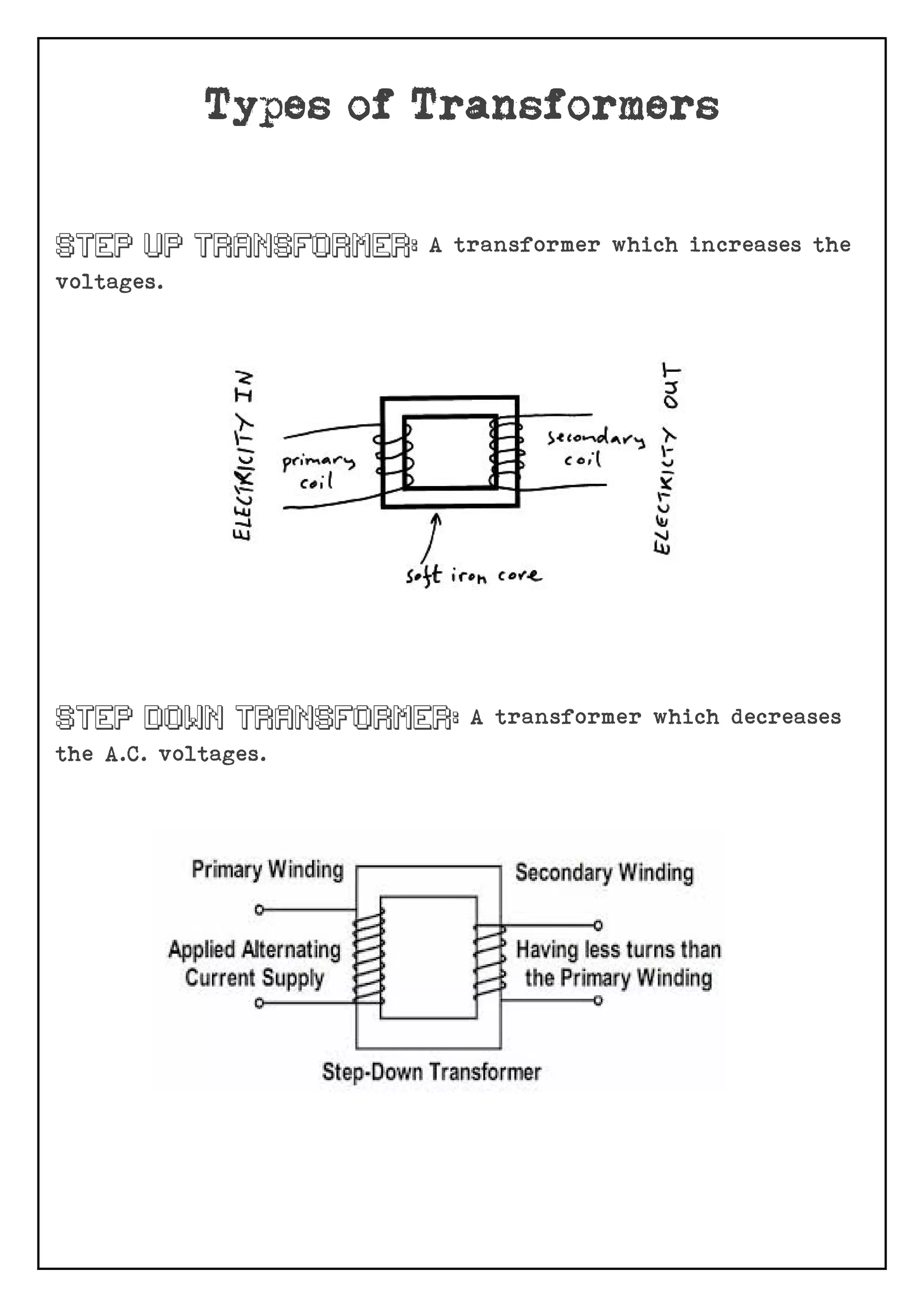
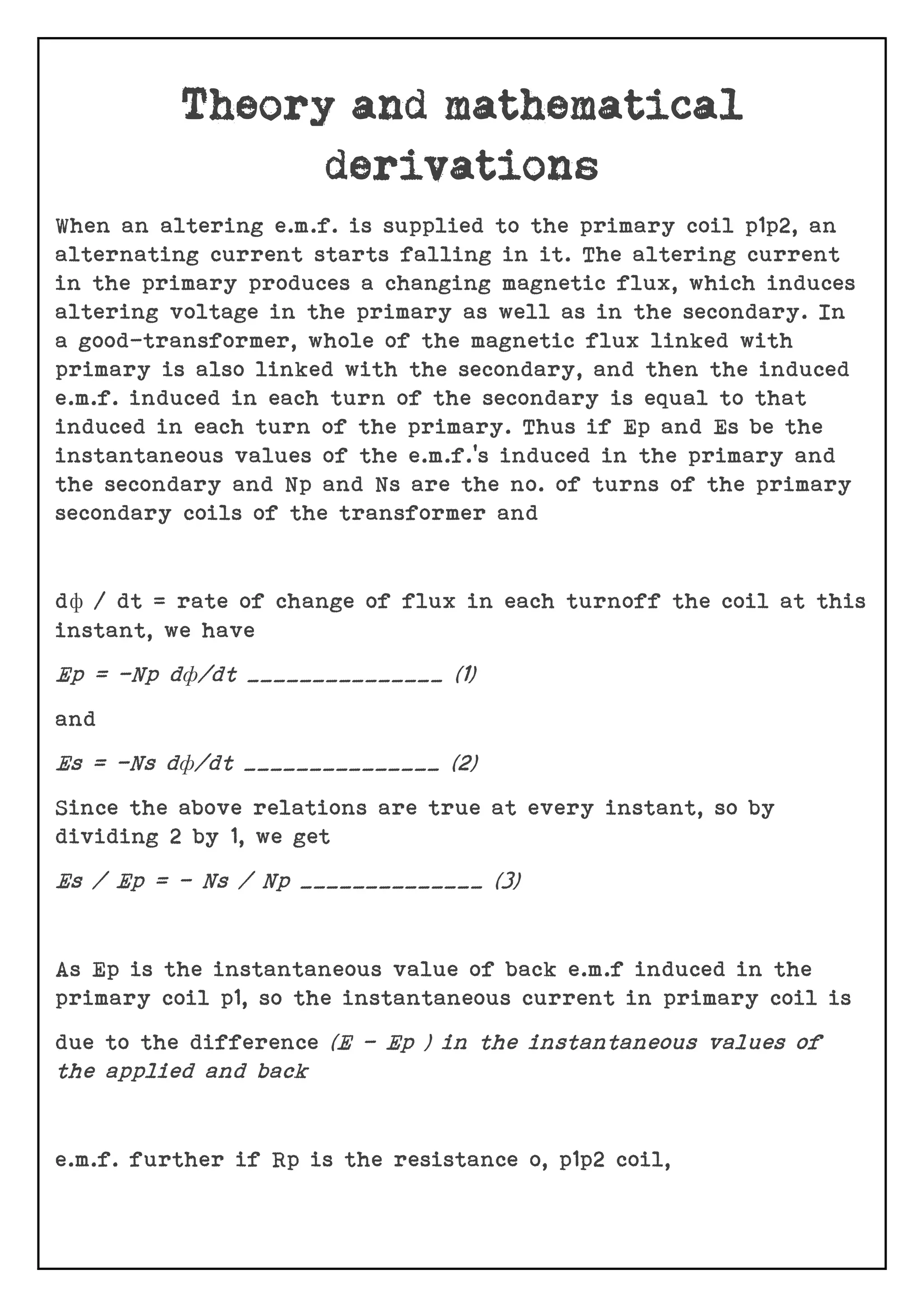
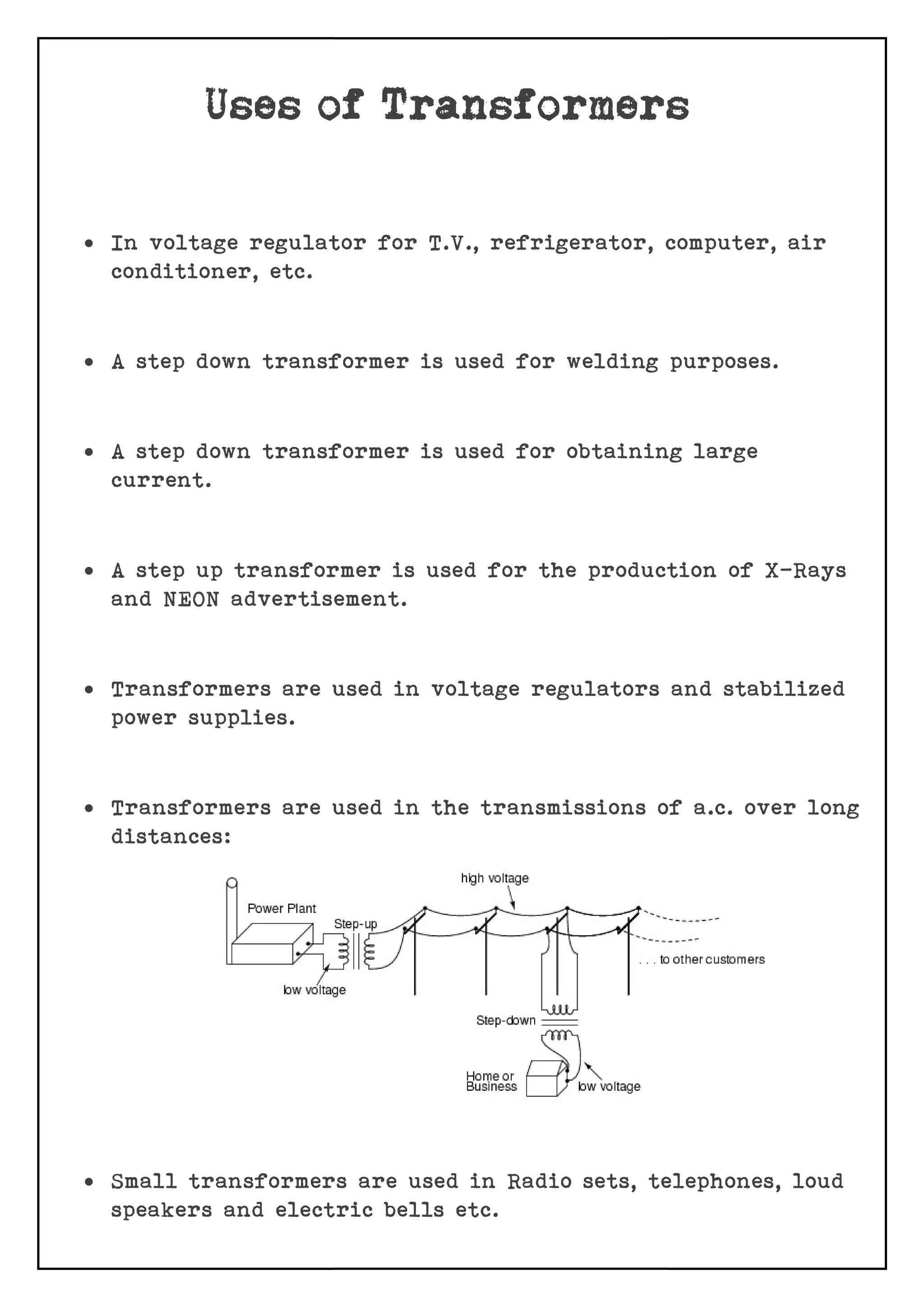
SUBMITTED BY: Vishesh Srivastava
SUBMITTED TO: Mr. Aditya Srivastava
I Vishesh Srivastava of Class 12th
Section A Shree Devi Ahilya
Shishu Vihar, Indore (M.P) Would Like to express my Sincere
Gratitude to our Respected Principal Mrs. Ranjana Naik and Vice
Principal Mrs. Aparna Vyas for Encouragement and help from
Time to Time during my Tenure as a Student of Class 12th
Section
A.
I also express my Sincere Gratitude towards My Physics Teacher
Mr. Aditya Srivastava for helping me in completing the Project
by useful Ideas and Guidelines. I thank him for encouraging me
throughout and helping in all possible ways.
I would also like to express my hearty gratitude to the lab
assistant Mrs. Sonal Neema for their support in completion of
the project.
I also thank my parents and friends for their vital support and
also for Encouragement and Motivation given to me for the
completion of the project.
Date of Submission: Vishesh Srivastava
This is to certify that Vishesh Srivastava of class 12th
Section A
has Worked on the Physics Project entitled “To investigate the
relation between the ratio of (i) Input and output voltage,
(ii)Number of turnings in the secondary coil and primary coil of
a self made transformer”. He has put on his sincere efforts to
collect the reading materials and has devoted sufficient periods
of Practical laboratory work to complete this project. This
project may be considered as Practical fulfilment of All India
Senior School Certificate Exam (AISSCE) 2016-2017 conducted by
CBSE.
Teachers’ signature Principal’s Signature
External Examiner’s Signature
To investigate the relation between the ratio of –
1. Input and output voltage.
2. Number of turnings in the secondary coil and primary coil of a
self made transformer
****
 Aim
 Introduction
 Types Of Transformers
 Theory And Mathematical Derivations
 Simple Circuit Diagram
 Circuit Diagrams Of Step-up and Step-Down Transformers
 Apparatus Required to make our Own Transformer
 Uses of Transformers
 Bibliography
****
The transformer is a device used for converting a low
alternating voltage to a high alternating voltage or vice-versa.
A Transformer based on the Principle of mutual induction
according to this principle, the amount of magnetic flux linked
with a coil changing, an e.m.f is induced in the neighboring coil.
A transformer is an electrical device which is used for changing
the A.C. voltages. A transformer is most widely used device in
both low and high current circuit. As such transformers are
built in an amazing strength of sizes. In electronic, measurement
and control circuits, transformer size may be so small that it
weight only a few tens of grams where as in high voltage power
circuits, it may weight hundred of tones.
****
A transformer which increases the
voltages.
A transformer which decreases
the A.C. voltages.
When an altering e.m.f. is supplied to the primary coil p1p2, an
alternating current starts falling in it. The altering current
in the primary produces a changing magnetic flux, which induces
altering voltage in the primary as well as in the secondary. In
a good-transformer, whole of the magnetic flux linked with
primary is also linked with the secondary, and then the induced
e.m.f. induced in each turn of the secondary is equal to that
induced in each turn of the primary. Thus if Ep and Es be the
instantaneous values of the e.m.f.’s induced in the primary and
the secondary and Np and Ns are the no. of turns of the primary
secondary coils of the transformer and
dф / dt = rate of change of flux in each turnoff the coil at this
instant, we have
Ep = -Np dф/dt _______________ (1)
and
Es = -Ns dф/dt _______________ (2)
Since the above relations are true at every instant, so by
dividing 2 by 1, we get
Es / Ep = - Ns / Np ______________ (3)
As Ep is the instantaneous value of back e.m.f induced in the
primary coil p1, so the instantaneous current in primary coil is
due to the difference (E – Ep ) in the instantaneous values of
the applied and back
e.m.f. further if Rp is the resistance o, p1p2 coil,
then the instantaneous current Ip in the primary coil is given
by
Ip = E – Ep / Rp
E – Ep = Ip Rp
Thus back e.m.f = input e.m.f
Hence equation 3 can be written as
Es / Ep = Es / E
= output e.m.f / input e.m.f
= Ns / Np = K
Where K is constant, called turn on transformation ratio.
****
In a step-down transformer,
secondary winding than in the primary winding in the step
transformers. Thus, the voltage supplied in the secondary
transformer is greater than the one supplied across the primary
winding. Because of the principl
transformer converts low voltage, high
low current. In other words, the voltage has been stepped up.
You can find step-up transformers located near power plants
that are designed to operate megawatt
power plants, step-up transformers can also be used for local
and smaller applications such as x
about 50,000 volts to work. Even a micro
small step-up transformer to operate.
transformer, There are many turns on the
secondary winding than in the primary winding in the step
transformers. Thus, the voltage supplied in the secondary
transformer is greater than the one supplied across the primary
winding. Because of the principle of conservation of energy, the
transformer converts low voltage, high-current to high voltage
low current. In other words, the voltage has been stepped up.
up transformers located near power plants
that are designed to operate megawatts of power. Apart from the
up transformers can also be used for local
and smaller applications such as x-ray machine which requires
about 50,000 volts to work. Even a micro-wave oven requires a
up transformer to operate.
There are many turns on the
secondary winding than in the primary winding in the step-up
transformers. Thus, the voltage supplied in the secondary
transformer is greater than the one supplied across the primary
e of conservation of energy, the
current to high voltage-
low current. In other words, the voltage has been stepped up.
up transformers located near power plants
s of power. Apart from the
up transformers can also be used for local
ray machine which requires
wave oven requires a
In a step-down transformer is one who secondary windings are
fewer than the primary windings. In other words, the
transformer’s secondary voltage is less than the primary
voltage. So, the transformer is designed to convert hi
low-current power into a low
is mainly used in domestic consumption.
A common case of step-down application is in the case of door
bells. Normally, door bells use 16 volts, but most household power
circuits carry 110-120 volts. Therefore, the doorbell’s step
transformer receives the 110 volts and reduces it to lower
voltage before supplying it to the doorbell.
Step-down transformers are mostly used to convert the 220 volts
electricity to the 110 volts re
down transformer is one who secondary windings are
fewer than the primary windings. In other words, the
transformer’s secondary voltage is less than the primary
voltage. So, the transformer is designed to convert hi
current power into a low-voltage, high current power and it
is mainly used in domestic consumption.
down application is in the case of door
bells. Normally, door bells use 16 volts, but most household power
120 volts. Therefore, the doorbell’s step
transformer receives the 110 volts and reduces it to lower
voltage before supplying it to the doorbell.
down transformers are mostly used to convert the 220 volts
electricity to the 110 volts required in most domestic equipment
down transformer is one who secondary windings are
fewer than the primary windings. In other words, the
transformer’s secondary voltage is less than the primary
voltage. So, the transformer is designed to convert high-voltage,
voltage, high current power and it
down application is in the case of door
bells. Normally, door bells use 16 volts, but most household power
120 volts. Therefore, the doorbell’s step-down
transformer receives the 110 volts and reduces it to lower
down transformers are mostly used to convert the 220 volts
quired in most domestic equipment.
 Iron Rod
 Copper Wire
 Hot Wire Ammeter
 Hot Wire Voltmeter
 Take thick iron rod and cover it with a thick paper and
wind a large number of turns of thin Cu wire on thick paper
(say 60). This constitutes primary coil of the transformer.
 Cover the primary coil with a sheet of paper and wound
relatively smaller number of turns (say 20) of thick copper
wire on it. This constitutes the secondary coil. It is a step
down transformer.
 Connect p1, p2 to A.C main and measure the input voltage and
current using A.C voltmeter and ammeter respectively.
 Similarly, measure the output voltage and current through
s1and s2.
 Now connect s1and s2to A.C main and again measure voltage
and current through primary and secondary coil of step up
transformer.
 Repeat all steps for other self made transformers by
changing number of turns in primary and secondary coil.
 In voltage regulator for T.V., refrigerator, computer, air
conditioner, etc.
 A step down transformer is used for welding purposes.
 A step down transformer is used for obtaining large
current.
 A step up transformer is used for the production of X
and NEON advertisement.
 Transformers are used in voltage regulators and s
power supplies.
 Transformers are used in the transmissio
distances:
 Small transformers are used in Radio sets, telephones, loud
speakers and electric bells etc
In voltage regulator for T.V., refrigerator, computer, air
A step down transformer is used for welding purposes.
A step down transformer is used for obtaining large
A step up transformer is used for the production of X
and NEON advertisement.
Transformers are used in voltage regulators and s
Transformers are used in the transmissions of a.c. over long
Small transformers are used in Radio sets, telephones, loud
speakers and electric bells etc.
In voltage regulator for T.V., refrigerator, computer, air
A step down transformer is used for welding purposes.
A step down transformer is used for obtaining large
A step up transformer is used for the production of X-Rays
Transformers are used in voltage regulators and stabilized
ns of a.c. over long
Small transformers are used in Radio sets, telephones, loud
 www.google.com
 www.wikipedia.org
 Physics NCERT
 Pradeep’s Physics
****

Physics investigatory project on transformers by vishesh

  • 1.
    SUBMITTED BY: VisheshSrivastava SUBMITTED TO: Mr. Aditya Srivastava
  • 2.
    I Vishesh Srivastavaof Class 12th Section A Shree Devi Ahilya Shishu Vihar, Indore (M.P) Would Like to express my Sincere Gratitude to our Respected Principal Mrs. Ranjana Naik and Vice Principal Mrs. Aparna Vyas for Encouragement and help from Time to Time during my Tenure as a Student of Class 12th Section A. I also express my Sincere Gratitude towards My Physics Teacher Mr. Aditya Srivastava for helping me in completing the Project by useful Ideas and Guidelines. I thank him for encouraging me throughout and helping in all possible ways. I would also like to express my hearty gratitude to the lab assistant Mrs. Sonal Neema for their support in completion of the project. I also thank my parents and friends for their vital support and also for Encouragement and Motivation given to me for the completion of the project. Date of Submission: Vishesh Srivastava
  • 3.
    This is tocertify that Vishesh Srivastava of class 12th Section A has Worked on the Physics Project entitled “To investigate the relation between the ratio of (i) Input and output voltage, (ii)Number of turnings in the secondary coil and primary coil of a self made transformer”. He has put on his sincere efforts to collect the reading materials and has devoted sufficient periods of Practical laboratory work to complete this project. This project may be considered as Practical fulfilment of All India Senior School Certificate Exam (AISSCE) 2016-2017 conducted by CBSE. Teachers’ signature Principal’s Signature External Examiner’s Signature
  • 4.
    To investigate therelation between the ratio of – 1. Input and output voltage. 2. Number of turnings in the secondary coil and primary coil of a self made transformer ****
  • 5.
     Aim  Introduction Types Of Transformers  Theory And Mathematical Derivations  Simple Circuit Diagram  Circuit Diagrams Of Step-up and Step-Down Transformers  Apparatus Required to make our Own Transformer  Uses of Transformers  Bibliography ****
  • 6.
    The transformer isa device used for converting a low alternating voltage to a high alternating voltage or vice-versa. A Transformer based on the Principle of mutual induction according to this principle, the amount of magnetic flux linked with a coil changing, an e.m.f is induced in the neighboring coil. A transformer is an electrical device which is used for changing the A.C. voltages. A transformer is most widely used device in both low and high current circuit. As such transformers are built in an amazing strength of sizes. In electronic, measurement and control circuits, transformer size may be so small that it weight only a few tens of grams where as in high voltage power circuits, it may weight hundred of tones. ****
  • 7.
    A transformer whichincreases the voltages. A transformer which decreases the A.C. voltages.
  • 8.
    When an alteringe.m.f. is supplied to the primary coil p1p2, an alternating current starts falling in it. The altering current in the primary produces a changing magnetic flux, which induces altering voltage in the primary as well as in the secondary. In a good-transformer, whole of the magnetic flux linked with primary is also linked with the secondary, and then the induced e.m.f. induced in each turn of the secondary is equal to that induced in each turn of the primary. Thus if Ep and Es be the instantaneous values of the e.m.f.’s induced in the primary and the secondary and Np and Ns are the no. of turns of the primary secondary coils of the transformer and dф / dt = rate of change of flux in each turnoff the coil at this instant, we have Ep = -Np dф/dt _______________ (1) and Es = -Ns dф/dt _______________ (2) Since the above relations are true at every instant, so by dividing 2 by 1, we get Es / Ep = - Ns / Np ______________ (3) As Ep is the instantaneous value of back e.m.f induced in the primary coil p1, so the instantaneous current in primary coil is due to the difference (E – Ep ) in the instantaneous values of the applied and back e.m.f. further if Rp is the resistance o, p1p2 coil,
  • 9.
    then the instantaneouscurrent Ip in the primary coil is given by Ip = E – Ep / Rp E – Ep = Ip Rp Thus back e.m.f = input e.m.f Hence equation 3 can be written as Es / Ep = Es / E = output e.m.f / input e.m.f = Ns / Np = K Where K is constant, called turn on transformation ratio. ****
  • 11.
    In a step-downtransformer, secondary winding than in the primary winding in the step transformers. Thus, the voltage supplied in the secondary transformer is greater than the one supplied across the primary winding. Because of the principl transformer converts low voltage, high low current. In other words, the voltage has been stepped up. You can find step-up transformers located near power plants that are designed to operate megawatt power plants, step-up transformers can also be used for local and smaller applications such as x about 50,000 volts to work. Even a micro small step-up transformer to operate. transformer, There are many turns on the secondary winding than in the primary winding in the step transformers. Thus, the voltage supplied in the secondary transformer is greater than the one supplied across the primary winding. Because of the principle of conservation of energy, the transformer converts low voltage, high-current to high voltage low current. In other words, the voltage has been stepped up. up transformers located near power plants that are designed to operate megawatts of power. Apart from the up transformers can also be used for local and smaller applications such as x-ray machine which requires about 50,000 volts to work. Even a micro-wave oven requires a up transformer to operate. There are many turns on the secondary winding than in the primary winding in the step-up transformers. Thus, the voltage supplied in the secondary transformer is greater than the one supplied across the primary e of conservation of energy, the current to high voltage- low current. In other words, the voltage has been stepped up. up transformers located near power plants s of power. Apart from the up transformers can also be used for local ray machine which requires wave oven requires a
  • 12.
    In a step-downtransformer is one who secondary windings are fewer than the primary windings. In other words, the transformer’s secondary voltage is less than the primary voltage. So, the transformer is designed to convert hi low-current power into a low is mainly used in domestic consumption. A common case of step-down application is in the case of door bells. Normally, door bells use 16 volts, but most household power circuits carry 110-120 volts. Therefore, the doorbell’s step transformer receives the 110 volts and reduces it to lower voltage before supplying it to the doorbell. Step-down transformers are mostly used to convert the 220 volts electricity to the 110 volts re down transformer is one who secondary windings are fewer than the primary windings. In other words, the transformer’s secondary voltage is less than the primary voltage. So, the transformer is designed to convert hi current power into a low-voltage, high current power and it is mainly used in domestic consumption. down application is in the case of door bells. Normally, door bells use 16 volts, but most household power 120 volts. Therefore, the doorbell’s step transformer receives the 110 volts and reduces it to lower voltage before supplying it to the doorbell. down transformers are mostly used to convert the 220 volts electricity to the 110 volts required in most domestic equipment down transformer is one who secondary windings are fewer than the primary windings. In other words, the transformer’s secondary voltage is less than the primary voltage. So, the transformer is designed to convert high-voltage, voltage, high current power and it down application is in the case of door bells. Normally, door bells use 16 volts, but most household power 120 volts. Therefore, the doorbell’s step-down transformer receives the 110 volts and reduces it to lower down transformers are mostly used to convert the 220 volts quired in most domestic equipment.
  • 13.
     Iron Rod Copper Wire  Hot Wire Ammeter  Hot Wire Voltmeter  Take thick iron rod and cover it with a thick paper and wind a large number of turns of thin Cu wire on thick paper (say 60). This constitutes primary coil of the transformer.  Cover the primary coil with a sheet of paper and wound relatively smaller number of turns (say 20) of thick copper wire on it. This constitutes the secondary coil. It is a step down transformer.  Connect p1, p2 to A.C main and measure the input voltage and current using A.C voltmeter and ammeter respectively.  Similarly, measure the output voltage and current through s1and s2.  Now connect s1and s2to A.C main and again measure voltage and current through primary and secondary coil of step up transformer.  Repeat all steps for other self made transformers by changing number of turns in primary and secondary coil.
  • 14.
     In voltageregulator for T.V., refrigerator, computer, air conditioner, etc.  A step down transformer is used for welding purposes.  A step down transformer is used for obtaining large current.  A step up transformer is used for the production of X and NEON advertisement.  Transformers are used in voltage regulators and s power supplies.  Transformers are used in the transmissio distances:  Small transformers are used in Radio sets, telephones, loud speakers and electric bells etc In voltage regulator for T.V., refrigerator, computer, air A step down transformer is used for welding purposes. A step down transformer is used for obtaining large A step up transformer is used for the production of X and NEON advertisement. Transformers are used in voltage regulators and s Transformers are used in the transmissions of a.c. over long Small transformers are used in Radio sets, telephones, loud speakers and electric bells etc. In voltage regulator for T.V., refrigerator, computer, air A step down transformer is used for welding purposes. A step down transformer is used for obtaining large A step up transformer is used for the production of X-Rays Transformers are used in voltage regulators and stabilized ns of a.c. over long Small transformers are used in Radio sets, telephones, loud
  • 15.
     www.google.com  www.wikipedia.org Physics NCERT  Pradeep’s Physics ****