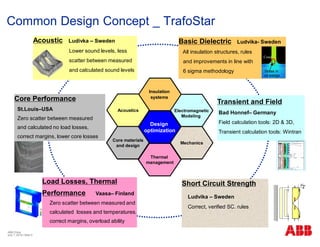
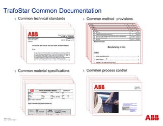
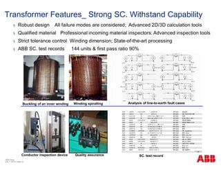
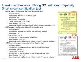
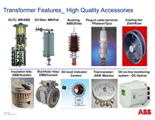
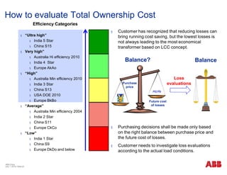
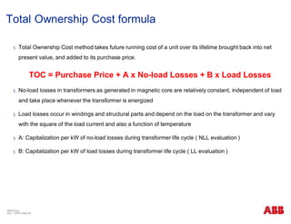
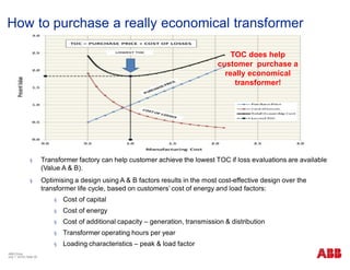
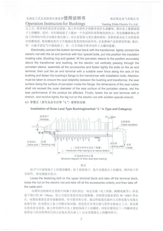
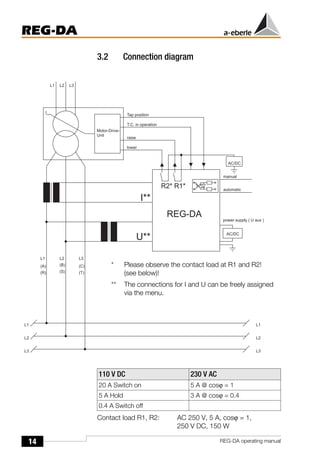
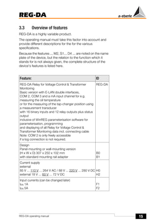
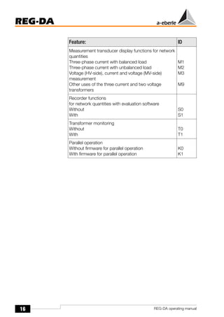
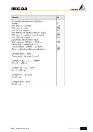
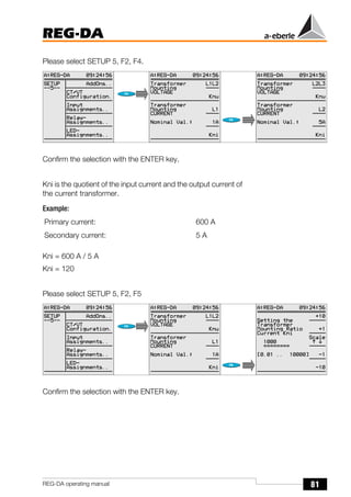
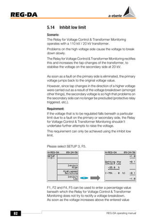
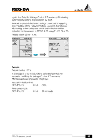
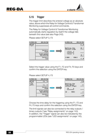
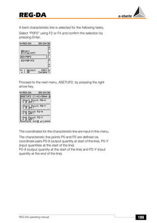
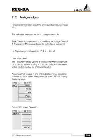
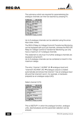
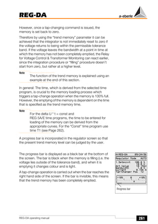
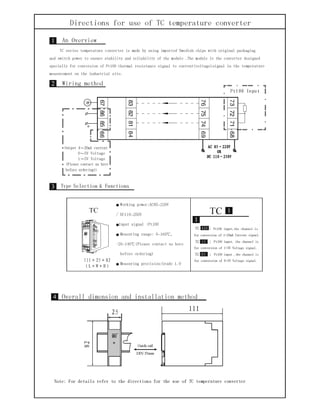
This document provides an overview of ABB transformers and manufacturing facilities in China. It discusses ABB's common design concept called TrafoStar, which utilizes a global design platform and database. TrafoStar aims to optimize transformer performance and quality. The document also outlines key features of ABB transformers, including their short circuit withstand capability, low sound levels, high quality accessories, and energy efficiency. It promotes evaluating transformers based on total ownership cost over the life cycle to find the most economical solution.


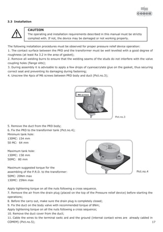
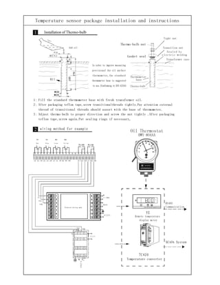
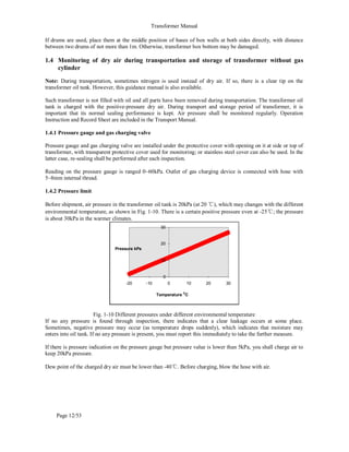
![71
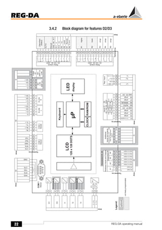
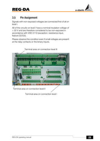
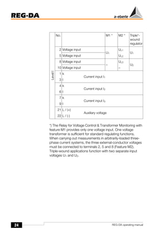
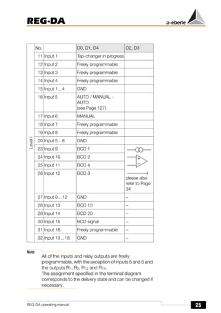
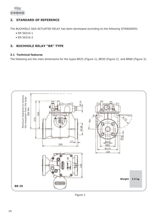
REG-DA
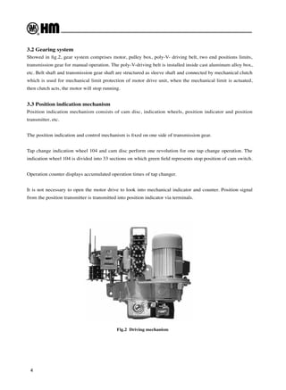
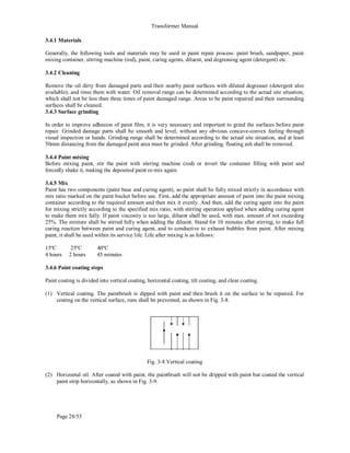
REG-DA operating manual
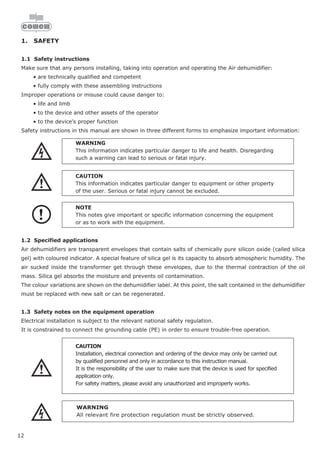
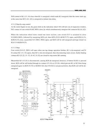
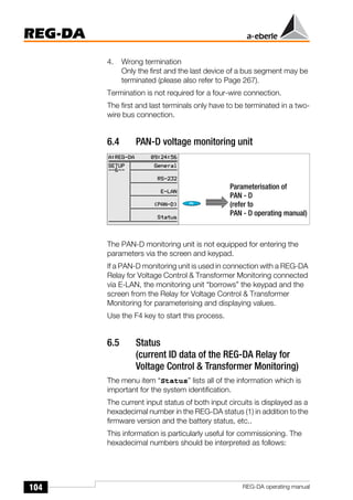
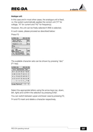
Note
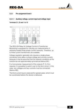
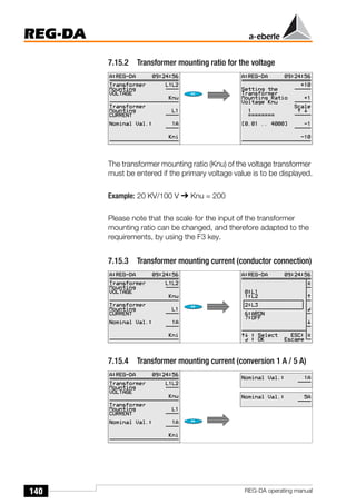
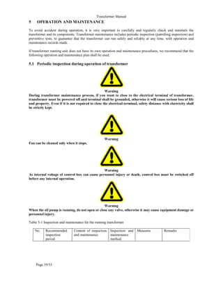
If the transformer mounting ratio (Knu) of the voltage
transformer is specified in a procedure carried out later,
then the primary voltage appears in kV in the second
row of the setpoint menu.
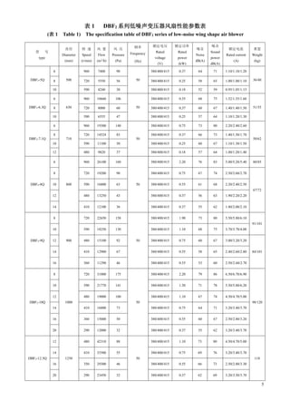
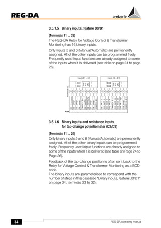
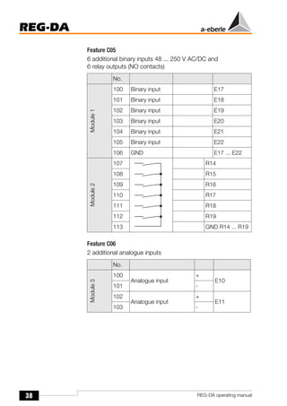
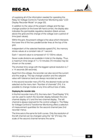
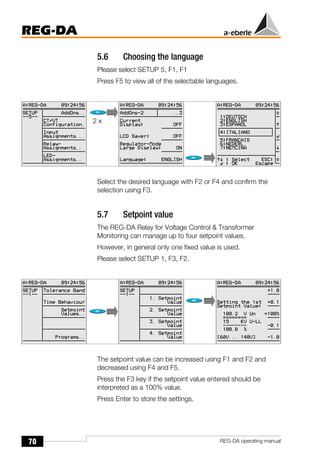
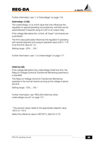
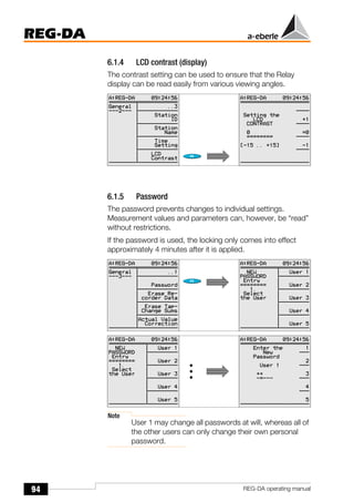
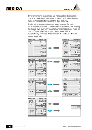
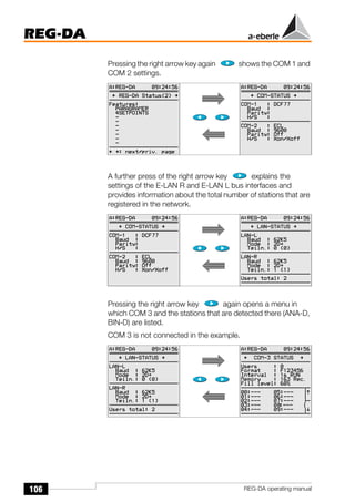
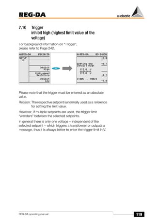
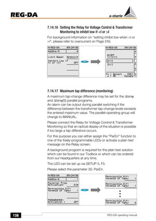
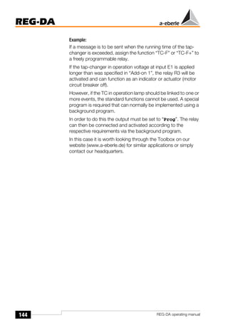
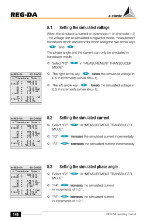
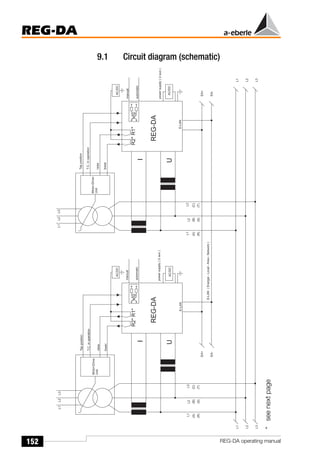
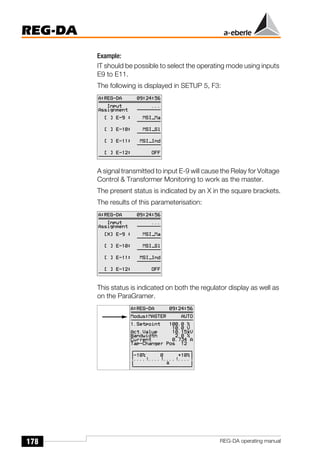
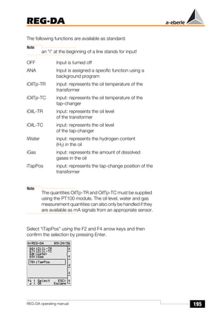
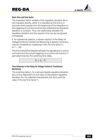
5.8 Permissible regulative deviation Xwz
There are two limits for setting the regulative deviation.
One limit is determined from the acceptable voltage tolerance
specified by the consumer, the other is defined by the tap-
change increment of the transformer.
The minimum voltage range can be calculated using the
following equation:
Xwz: Permissible regulative deviation
If a regulative deviation Xwz that is smaller than the tap-change
increment of the transformer is selected, the controlled system
can never reach a stable condition; the Relay for Voltage
Control & Transformer Monitoring will continue to increment in
steps.
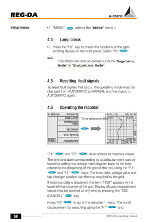
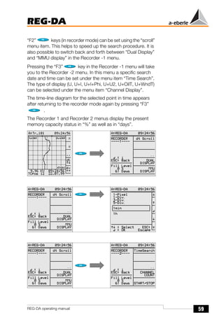
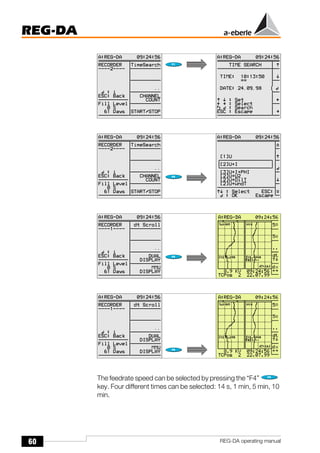
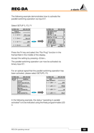
Please select SETUP 1, F1.
The permissible regulative deviation can be increased using F1
and F2 and decreased using F4 and F5.
The parameter is confirmed by pressing Enter.
Xwz[%] ≥ 0.6 · tap-change increment[%]](https://image.slidesharecdn.com/re-hfy3-3130-ved-080-ele-man-0006atrainingmanual-230922232824-a612d134/85/ABB-Training-Manual-pdf-192-320.jpg)
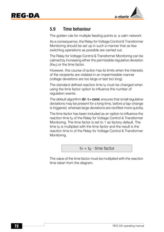
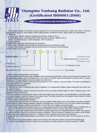
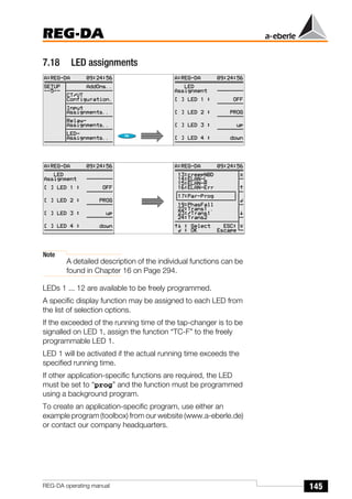
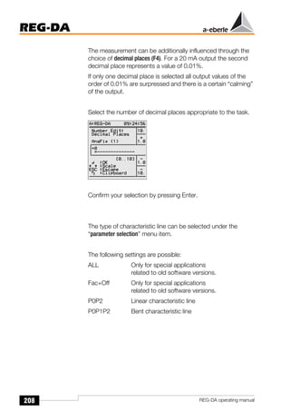
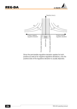
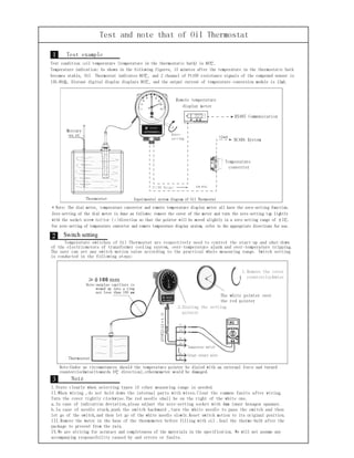
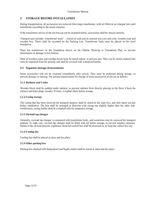
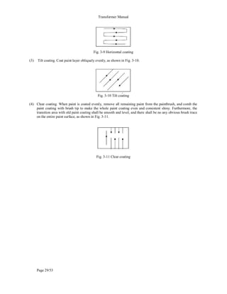
![73
REG-DA
REG-DA operating manual
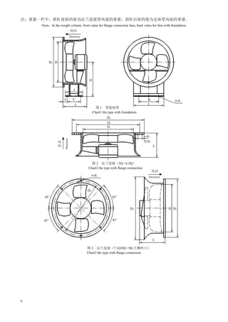
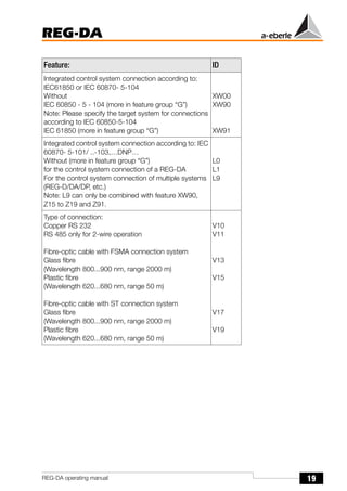
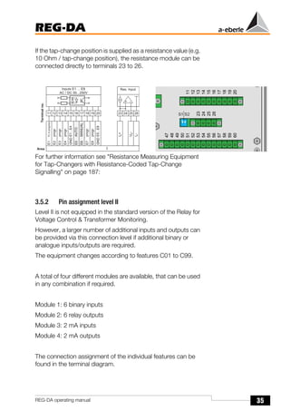
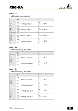
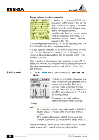
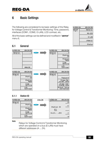
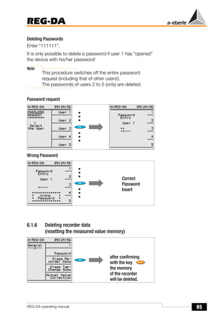
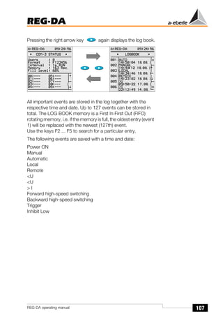
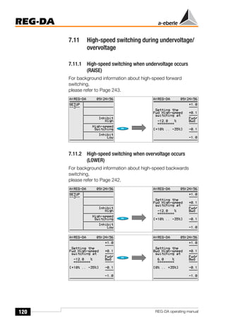
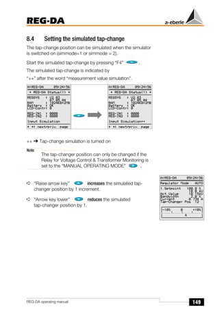
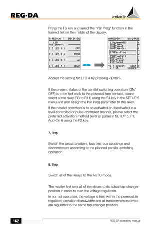
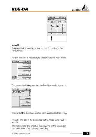
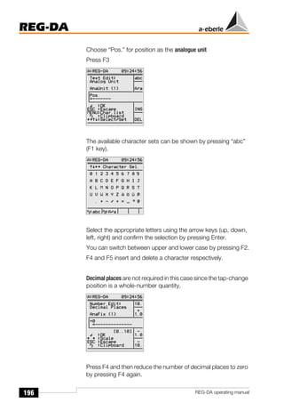
Example:
Present regulative deviation
Xw = 4%;
Permissible regulative deviation Xwz = 2%
tv = tB · time factor
(range of the time factor: 0,1 ... 30
see SETUP 1, F2, F3)
→ with time factor: 1: 15 sec;
→ with time factor: 2: 30 sec;
Note
In practice, a time factor between 2 and 3 is used.
However, a general recommendation cannot be given,
since the correct time factor is dependent on both the
network and the customer configuration.
Please select SETUP 1, F2, F3 and enter the time factor using
F1, F2 and F4, F5.
Reaction
time
t
B
[sec]
for
time
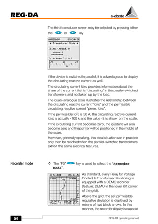
factor:
1
25
20
15
10
5
0
0 1 2 3 4 5 6 7 8 9 10
Present regulative deviation UW [%]
Set permissible
regulative deviation](https://image.slidesharecdn.com/re-hfy3-3130-ved-080-ele-man-0006atrainingmanual-230922232824-a612d134/85/ABB-Training-Manual-pdf-194-320.jpg)
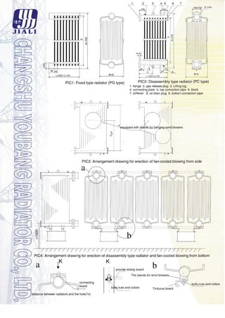
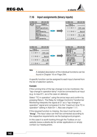
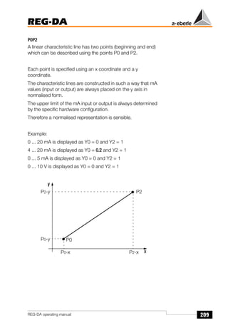
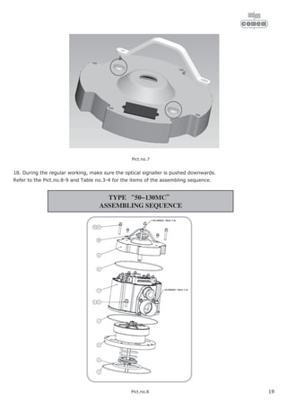
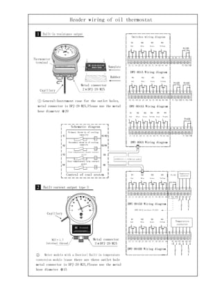
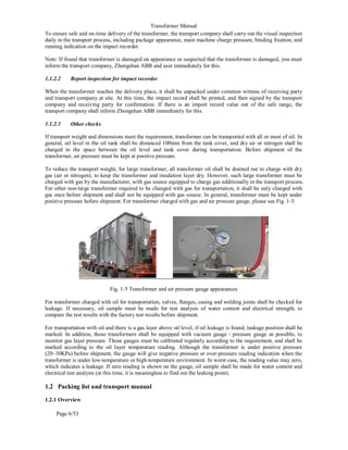
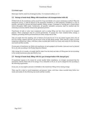
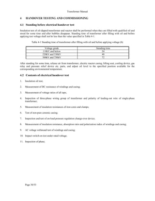
![75
REG-DA
REG-DA operating manual
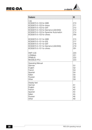
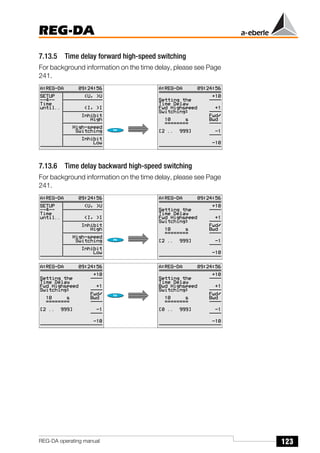
5.10 Backward high-speed switching
While the Relay for Voltage Control & Transformer Monitoring is
operating according to the algorithm dU · t = const., events will
always be regulated such that the next tap-change will be
triggered after a short time for large deviations and after a long
time for small deviations.
Example:
The curve below gives a time of 42 s, the time within which the
fault will be rectified.
High-speed switching can be used to reduce this time.
If, in the above example, the high-speed switching limit were set
to 6%, the Relay for Voltage Control & Transformer Monitoring
would switch the voltage back to the permissible range of the
voltage tolerance band as soon as this limit is reached and the
selected time delay for high-speed mode has passed.
Permissible regulative deviation Xwz: 1%
Present regulative deviation Xw: +6%
Time factor: 1
Tap-change increment of the transformer: 1,5%
Reaction
time
t
B
[sec]
for
time
factor:
1
25
20
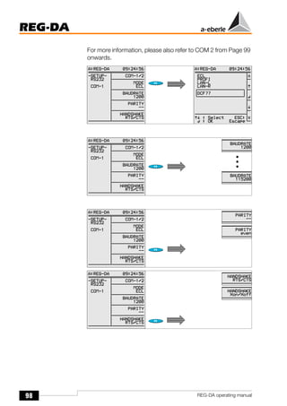
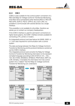
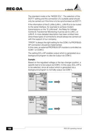
15
10
5
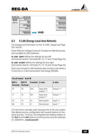
0
0 1 2 3 4 5 6 7 8 9 10
Present regulative deviation UW [%]
Tap-change 1
Tap-change 2
Tap-change 3
Tap-change 4
Set permissible
regulative deviation](https://image.slidesharecdn.com/re-hfy3-3130-ved-080-ele-man-0006atrainingmanual-230922232824-a612d134/85/ABB-Training-Manual-pdf-196-320.jpg)

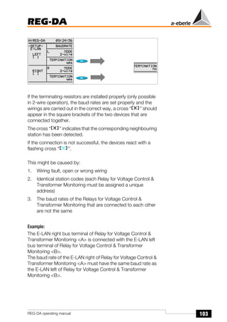


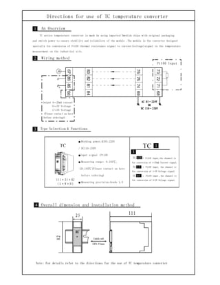
![157
REG-DA
REG-DA operating manual
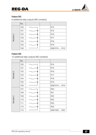
This address may be incremented using the F1 and F2 keys or
decremented using the F4 and F5 keys.
Confirm your selection using <Enter>.
Each address in the range A ... Z4 is permitted, however each
station code may only be assigned once.
If the PAN-D voltage monitoring unit is assigned to a REG-DA
Relay for Voltage Control & Transformer Monitoring, the Relay
for Voltage Control & Transformer Monitoring will automatically
assign a code to its corresponding PAN-D.
To assign this address, the REG-DA Relay for Voltage Control
& Transformer Monitoring increments its own address (by one!)
and assigns it to the PAN-D.
Example:
If the Relay for Voltage Control & Transformer Monitoring has
the code <A>, it will assign the code <A1> to the PAN-D. If the
Relay for Voltage Control & Transformer Monitoring has the
code <B9>, it will assign the code <C> to the PAN-D.
3. Step
Establish the connection to the bus.
To start the parallel operation, all participating Relays must be
able to communicate with each other via E-LAN.
This requires that the bus link (2-conductor or 4-conductor bus)
is connected in the line-to-line or standard bus structure.
Once the hardware prerequisites are fulfilled, the bus link must
be parameterised [see "E-LAN (Energy-Local Area Network)"
on page 101].](https://image.slidesharecdn.com/re-hfy3-3130-ved-080-ele-man-0006atrainingmanual-230922232824-a612d134/85/ABB-Training-Manual-pdf-278-320.jpg)
![167
REG-DA
REG-DA operating manual
Example:
If the Relay for Voltage Control & Transformer Monitoring has
the code <A>, it will assign the code <A1> to the PAN-D. If the
Relay for Voltage Control & Transformer Monitoring has the
code <B5>, it will assign the code <B6> to the PAN-D.
3. Step
Establish the connection to the bus.
To start the parallel operation, all parallel-operating Relays must
be able to communicate with each other via E-LAN.
This requires that the bus link (2-conductor or 4-conductor bus)
is connected in the line-to-line or standard bus structure.
The bus link must be parameterised [see "E-LAN (Energy-Local
Area Network)" on page 101] once the hardware prerequisites
are fulfilled.
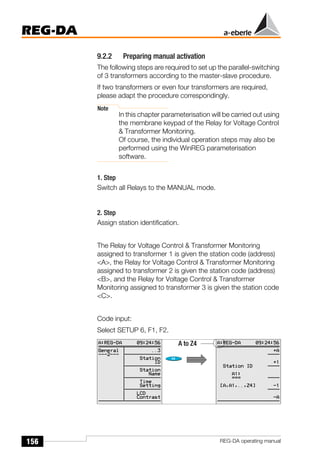
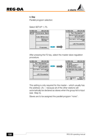
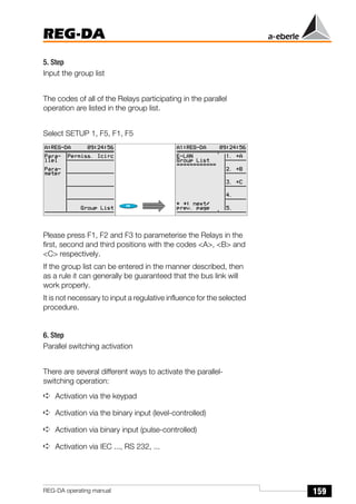
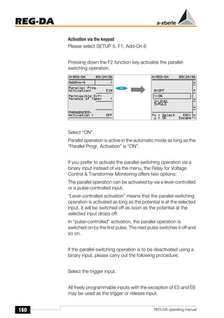
4. Step
Activate the ParaGramer.
Please select SETUP 5, F1, Add-On 6, F5 and activate the
ParaGramer by selecting the number of transformers operating
in parallel.
For three parallel-operating transformers select: ON-3](https://image.slidesharecdn.com/re-hfy3-3130-ved-080-ele-man-0006atrainingmanual-230922232824-a612d134/85/ABB-Training-Manual-pdf-288-320.jpg)
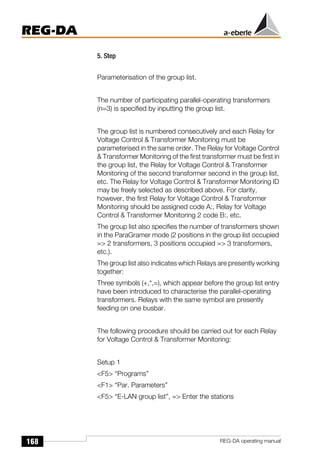

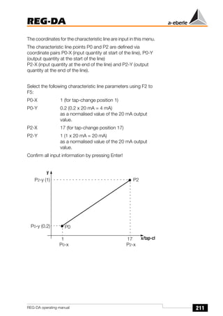
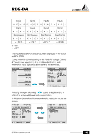
![213
REG-DA
REG-DA operating manual
The built-in simulator can be used to check the settings (see
chapter 8).
Simulate a tap-change (see chapter 8.4 on Page 149).
Select SETUP 6, F1, F5 again. The ANALOGUE I/O [1-4] menu
will appear in the display.
If the left arrow key is pressed in this menu, the actual output
value of the analogue value will be displayed.
Assuming that tap-change position 17 has been simulated,
AnaR 3 delivers an output of 20 mA that can be checked using
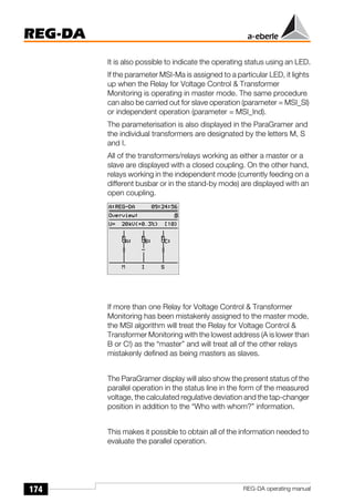
a mA meter.
Pressing the left arrow key again displays the normalised value
of the output quantity.
If 20 mA hardware is being used, the normalised value
AnaN 1 = 1 if 20 mA is flowing, and AnaN 1 = 0.2 if only 4 mA
is flowing (level 1).
The parameterisation has now been completed.
Press the ESC key twice to return to the regulator, transducer,
recorder, etc. in the main menu.](https://image.slidesharecdn.com/re-hfy3-3130-ved-080-ele-man-0006atrainingmanual-230922232824-a612d134/85/ABB-Training-Manual-pdf-334-320.jpg)
![228
REG-DA
REG-DA operating manual
The change to another setpoint value can be activated either via
an external signal or by using a background program.
15.2.2 Variable command variable
The command variable W for regulating the voltage at a given
position on a line is the sum of a fixed setpoint value XR and the
variable value of a correction value XK.
W [V] = XR [V] + XK [V]
The correction value XK takes the data of the assigned line and
load into consideration (voltage drop Uf), so that the voltage at
the given position − the load point of the line − can be held
approximately constant.
It is assumed that the network is generally loaded
symmetrically, i.e. that the current in each line is approximately
the same. The REG-DA Relay for Voltage Control &
Transformer Monitoring can therefore be connected to the
current transformer of any line (L1, L2, L3).
Measuring the voltage drop Uf on the line
The voltage drop Uf on the line between the transformer and
the consumer is the difference between the r.m.s. values of
both voltages on the busbar and at the load point. The voltage
drop depends on the impedance of the line, the current
strength and the cos ϕ at the consumer.
The following formula defines the impedance of a line:
Z = RL + j ω LL + 1 / j ω CL
Measuring the voltage drop Uf as a function of the rated current
When the reactances of the line can be neglected and the cos
ϕ at the consumer remains constant, the voltage drop Uf can
be measured as a function of the nominal current.
Uf = f (I, R)
The gradient of the Uf/IL characteristic line required for the
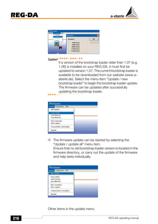
correct measurement of Uf must be determined according to](https://image.slidesharecdn.com/re-hfy3-3130-ved-080-ele-man-0006atrainingmanual-230922232824-a612d134/85/ABB-Training-Manual-pdf-349-320.jpg)
![231
REG-DA
REG-DA operating manual
15.2.3 Current-dependent setpoint value increment
Determining the voltage levels XR and Uf
The voltage level XR (setpoint value) should correspond to the
required voltage at a minimum current.
The voltage level Uf is a function of the gradient of the linear Uf/
IL-characteristic line. Adding this voltage to the entered setpoint
value XR (increasing the setpoint value) cancels out the voltage
drop on the line.
Various programs are available for incrementing the setpoint
value:
❑ setpoint value increment dependent on apparent current
❑ setpoint value increment dependent on active current
❑ setpoint value increment dependent on reactive current.
The line-drop compensation using the LDC process was
described in the previous chapter.
Apart from the LDC process, the most commonly used method
is compensation based on the apparent current and this is
described in more detail below.
Please observe that the positive or negative sign of the active
power is taken into consideration when the current-dependent
setpoint value is increased.
The current-dependent setpoint value increment is active if
power is being consumed and is inactive when power is being
supplied.
This procedure - which works in the interest of network
operation - can only be carried out properly and reliably when
the direction of the active power is input correctly.
Uf [V]
0
0
IL
107.5 V 21.5 kV
100 V 20 kV
100 A 700 A 800 A
5 A
0.625 A 4.375 A
4.688 V
6.563 V
7.5 V](https://image.slidesharecdn.com/re-hfy3-3130-ved-080-ele-man-0006atrainingmanual-230922232824-a612d134/85/ABB-Training-Manual-pdf-352-320.jpg)
![232
REG-DA
REG-DA operating manual
In this case a positive sign for active power indicates incoming
power (setpoint value increment permissible), whereas a
negative sign indicates power supply, and the setpoint
increment function is disabled.
The connections for both the voltage and the current must be
correctly assigned in order to detect the direction of the active
power.
Therefore, please check the connections for current and
voltage, as well as the assignments (SETUP 5, F2) and lastly
check the sign for active power in the measurement transducer
mode.
Nominal value of the gradient
The nominal value of the gradient Gnom indicates the % change
in the nominal voltage when the current strength changes from
0 to 100% of the I1n nominal current of the current transformer
that is mounted in the network.
GNom = 100 V
(∆U in relation to ∆IL [A])
Thus for the voltage Uf = f (I)
Limitation of the voltage level Uf
To prevent the command variable from exceeding a certain limit
value in the event of overcurrent, the gradient of the linear Uf/IL
characteristic line must be set to zero from a specified value of
the current onwards. The characteristic line is horizontal after
this point.
GNom %
[ ]
∆U V
[ ]
UNom V
[ ]
---------------------- 100%
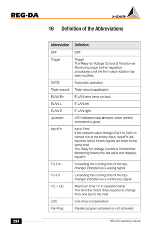
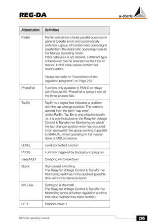
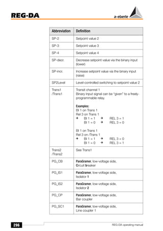
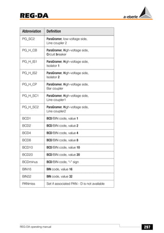
⋅
=
Uf V
[ ] ∆U V
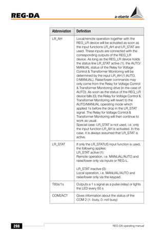
[ ]
=
GNom %
[ ]
100%
-----------------------
- UNom V
[ ]
Ipresent A
[ ]
I1N A
[ ]
--------------------------
-
⎝ ⎠
⎛ ⎞
⋅ ⋅
=](https://image.slidesharecdn.com/re-hfy3-3130-ved-080-ele-man-0006atrainingmanual-230922232824-a612d134/85/ABB-Training-Manual-pdf-353-320.jpg)
![233
REG-DA
REG-DA operating manual
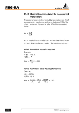
Measuring the required gradient
The two value pairs, voltage and current strength, must be
known at a light load as well as at full load to measure the
required nominal value Gnom [%].
Please note that the gradient and the setpoint value cannot be
set independently from each other for this type of characteristic
line, because when Gnom [%] > 0%, the command variable W,
which is already at the minimum current value Imin > 0, would be
unintentionally increased.
Example:
The voltage at a particular point in the network is to be held
constant at 20 kV under a variable load.
Nominal values of the voltage transformer:
U1n = 20 kV; U2n = 100 V; Knu = 200
Nominal values of the current transformer:
I1n = 800 A; I2n = 5 A; Kni = 160
Measured value pairs:
Primary side:
The difference between the currents
∆I [A] = Imax - Imin = 700 A - 100 A = 600 A
Secondary side (primary values/Kni):
The difference between the currents
∆I [A] = Imax - Imin = 4.375 A - 0.625 A = 3.750 A
Absolute voltage change
∆U [V] = 21.5 kV - 20.5 kV = 1.0 kV
Voltage change in percent
∆U [%] = (1.0 kV / 20.0 kV) 100 % = 5 %
Values at
light load Pmin
Values at
full load Pmax
Current intensity I Imin = 100 A Imax = 700 A
Control variable w wmin = 20.5 kV wmax = 21.5 kV](https://image.slidesharecdn.com/re-hfy3-3130-ved-080-ele-man-0006atrainingmanual-230922232824-a612d134/85/ABB-Training-Manual-pdf-354-320.jpg)
![234
REG-DA
REG-DA operating manual
To raise the voltage of the transformer at full load (Imax) to
21.5 kV, the command variable must be ∆U = 1.0 kV, or 5% of
the nominal voltage U1n higher than the set setpoint value XR.
Calculating the nominal value of the gradient Gnom [%]
Setpoint value reduction
With a light load and this gradient, the command variable W
would be increased to
This corresponds to (100 A / 800 A) 6.67% = 0.83% of the
nominal voltage.
Thus, the setpoint value XR would have to be set lower by
0.83% in order to maintain the voltage level at 20.5 kV during a
light load.
Adjusting the setpoint values
At full load, the reduction of the setpoint value, however, causes
the command variable W to be lowered so that a compromise
must be found between the increase in Gnom [%] and the
decrease in the reduction of the setpoint value.
GNom %
[ ]
∆U V
[ ]
UNom V
[ ]
---------------------- 100 %
I1N
∆I
-------
-
⋅
⋅
=
GNom %
[ ]
1.0 kV
20 kV
---------------
- 100 %
800 A
600 A
--------------
- 6.67 %
=
⋅
⋅
=
W 1
Imin
I1n
---------
⎝
⎛
+
GNom
100%
-------------
-
⎠
⎞ UNom
⋅ ⋅
=
W 1
100 A
800 A
--------------
-
⎝
⎛
+
6.67%
100%
---------------
⎠
⎞ 20.5 kV 20.67 kV
=
⋅ ⋅
=](https://image.slidesharecdn.com/re-hfy3-3130-ved-080-ele-man-0006atrainingmanual-230922232824-a612d134/85/ABB-Training-Manual-pdf-355-320.jpg)
![236
REG-DA
REG-DA operating manual
No further increase takes place once the 4 V limit is
reached.
The tolerance band remains unchanged. The permissible
regulative deviation is not affect by the voltage increase.
The setpoint value, corrected to include the voltage increase, is
not shown. However, it is indicated by the black colour of the
arrow in the bar graph display.
Current-dependent voltage increase
The currently-active setpoint value Uset,corr. is calculated as
follows:
If ∆U > ∆B, then ∆U is limited to the size of ∆B.
Current-influencing programs
Apparent current: Ixd = I
The apparent current is used to determine the voltage increase.
Increases only take place when the active power is positive.
Uset corr
, Uset ∆U
+
= ∆U
Grad
100 %
--------------
- 100 V
×
Ixd
In
------
×
=
Setpoint value [V]
Upper
tolerance band
Setpoint
Lower
tolerance band
106
107
105
104
103
102
101
100
99
98
0 0.2 0.4 0.6 0.8 1
Current normalised to 1/5 A.
Gradient = 5 %
Limitation = 4 %
Setpoint value = 100 V = 100 %
Permissible regulative deviation = 1 %](https://image.slidesharecdn.com/re-hfy3-3130-ved-080-ele-man-0006atrainingmanual-230922232824-a612d134/85/ABB-Training-Manual-pdf-357-320.jpg)
![237
REG-DA
REG-DA operating manual
This method can be used to compensate the voltage drop if
cosϕ is relatively constant.
Active current: Isd = Iw = I x cosϕ (with +/- sign)
The active current is used to determine the change in the
setpoint value. If a negative active current flows (energy fed
back), the setpoint value is decreased. The limitation is
symmetrical and applies to both increases and decreases.
Reactive current: Ixd = Ib = I x sinϕ (with +/- sign)
The reactive current is used to determine the voltage increase.
The increase/decrease is independent of the sign of the active
power. It is increased if the reactive current is inductive, and
decreased if it is capacitive.
This program is primarily used if the cosϕ of the network varies
by a large amount.
LDC (Line Drop Compensation):
Used to compensate the voltage drop on a line when the active
and reactive resistances are known. This process can also be
used if the cosϕ of the consumer is not constant. The gradient
is not required for this process. The limitation, however,
continues to apply.
Abbreviations
Ixd: Current used to determine the voltage increase [A]
I: Apparent current, measurement quantity [A]
Iw: Active current [A]
Ib: Reactive current [A]
In: Nominal current of the current transformer 1/5 A [A]
Grad.: Gradient [%]
Lim.: Limitation [L]
∆B: Limitation of the voltage increase [V]
∆U: Increase in setpoint value [V]
Uset: Specified setpoint value [V]
Uset,corr the setpoint value corrected to include the voltage
increase [V]](https://image.slidesharecdn.com/re-hfy3-3130-ved-080-ele-man-0006atrainingmanual-230922232824-a612d134/85/ABB-Training-Manual-pdf-358-320.jpg)
![238
REG-DA
REG-DA operating manual
15.4 Regulative deviations
15.4.1 Regulative deviation Xw
The regulative deviation Xw is the difference between the actual
value X of the regulating variable and the command variable W.
The sign of the regulative deviation can be plus or minus.
Note
The regulative deviation Xw corresponds to the negative
regulation difference Xd.
15.4.2 Permissible regulative deviation Xwz
To minimise the number of switches of the tap-changer, a
deviation in the network voltage from the command variable W
is tolerated within certain limits, i.e. a specific regulative
deviation is permissible.
This permissible regulative deviation Xwz is entered as a ± n%
of the control variable W (independent of all the other limit values
expressed in %) and sets the limits for the maximum
permissible relative fluctuation of the network voltage above
and below the control value W. For this reason the absolute limit
values of the tolerance band are dependent on the set
command variable W.
When the network voltage dips into this tolerance band, the
regulation procedure is interrupted and the integrator is set to
zero so that the regulation/integration process only begins
again when the network voltage overshoots or undershoots the
limits of the tolerance band.
Fluctuations in the network voltage within the permissible
regulative deviation have no effect on the regulation procedure.
Xw V
[ ] X V
[ ] W V
[ ]
Xw %
[ ] W V
[ ]
⋅
100 %
-----------------------------------
-
=
–
=
Xw %
[ ]
Xw V
[ ]
W V
[ ]
---------------- 100 %
⋅
=](https://image.slidesharecdn.com/re-hfy3-3130-ved-080-ele-man-0006atrainingmanual-230922232824-a612d134/85/ABB-Training-Manual-pdf-359-320.jpg)
![239
REG-DA
REG-DA operating manual
15.4.3 Displaying the regulative deviation Xw
The deviation of the network voltage X from the command
variable W is indicated analogously on the scale of the
regulator. The colour of the pointer changes from light to dark
when the voltage exceeds the permissible regulative deviation
Xwz.
When indicating the permissible regulative deviation Xwz, the
setpoint value correction Xk for compensating the voltage drop
in the line is not taken into consideration.
15.4.4 Setting the permissible regulative deviation Xwz
The tolerance band determined by the permissible regulative
deviation Xwz (± n% of the control variable W) must be higher than
the tap-change of the transformer in percent, because
otherwise the changed output voltage of the transformer would
violate the opposite limit of the permissible regulative deviation
after a control command has been executed. Furthermore,
after having reached the integral value, a control command
would be output to reset the previous transformer tap-changer
position. This procedure would be constantly repeated, i.e. this
would lead to frequent tap-changes of the transformer and thus
to unwanted fluctuations in the network voltage.
In order to have sufficient distance from the upper and lower
limits of the permissible regulative deviation, the following
formula applies
2 ⋅ |± Xwz [%]| > ∆UTap [%]
or
|± Xwz [%]| > 0.5 ∆UTap [%]
Guide value for Xwz
The following guide value is generally recommended for the
permissible regulative deviation Xwz:
|± Xwz [%]| ≥ 0.6 ∆UTap [%]](https://image.slidesharecdn.com/re-hfy3-3130-ved-080-ele-man-0006atrainingmanual-230922232824-a612d134/85/ABB-Training-Manual-pdf-360-320.jpg)
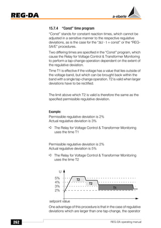
![255
REG-DA
REG-DA operating manual
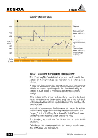
15.7.1 Determining the reaction delay tv
Hyperbolic characteristic curve Xw/tg (setting the time behaviour:
∆U*t=const)
Time factor = 1
Set regulative deviation = 1%
Constant present regulative deviation = 2%
➪ Time until tap-change: 15 s
Note
Please note that the actual switching time delay can
exceed the parameterised switching time delay by up to
2 seconds. This difference is due to the procedure
selected for determining the measurement values.
Reaction time tg [sec]
30
25
20
15
10
5
0
0 1 2 3 4 5 6 7 8 9 10
Present regulative deviation ∆UW [%]
Set permissible
regulative deviation](https://image.slidesharecdn.com/re-hfy3-3130-ved-080-ele-man-0006atrainingmanual-230922232824-a612d134/85/ABB-Training-Manual-pdf-376-320.jpg)
![256
REG-DA
REG-DA operating manual
A black bar increases from left to right at the bottom of the
quasi-analogue display in regulator mode. This bar shows how
long it will take until the next control command is issued.
The command is issued when the bar reaches the right hand
edge of the display.
Exception: if the bar reaches the edge after 5 seconds whilst a
tap-change is being carried out, the Relay for Voltage Control &
Transformer Monitoring waits for this process to be completed
before a new tap-change operation is started.
Hyperbolic characteristic curve Xw/tg (setting the time behaviour: REG-
5A/E)
Time factor = 1
Set regulative deviation = 1%
Constant present regulative deviation = 2%
➪ Time until tap-change: 10 s
Note
Please note that the actual switching time delay can
exceed the parameterised switching time delay by up to
2 seconds. This difference is due to the procedure
selected for determining the measurement values.
Progress bar
Reaction time tg [sec]
30
25
20
15
10
5
0
0 1 2 3 4 5 6 7 8 9 10
Present regulative deviation ∆UW [%]
Set permissible
regulative deviation](https://image.slidesharecdn.com/re-hfy3-3130-ved-080-ele-man-0006atrainingmanual-230922232824-a612d134/85/ABB-Training-Manual-pdf-377-320.jpg)
![257
REG-DA
REG-DA operating manual
Further examples:
The permissible regulative deviation is set to Xwz = ± 2%, the
time factor is set to 5. From the set of curves, the curve for Xwz
= ± 2% has been selected. Using the curve, one obtains the
following values:
How to proceed:
Determine the point of intersection of the Y-coordinate at Xw
with the curve of the permissible regulative deviation set on the
Relay for Voltage Control & Transformer Monitoring. The value
of the Y-coordinate corresponds to the basic time (see
graphic).
A black bar increases from left to right at the bottom of the
quasi-analogue display in regulator mode. This bar shows how
long it will take until the next control command is issued..
The command is issued when the bar reaches the right hand
edge of the display.
Exception: if the bar reaches the edge after 5 seconds whilst a
tap-change is being carried out, the Relay for Voltage Control &
Transformer Monitoring waits for this process to be completed
before a new tap-change operation is started.
Xw [%] = [(X - W)/W] 100% 2% 3% 4% 5% 10%
Basic time tg (s) from the curve 30 s 16 s 10 s 7 s 2 s
Switching delay
= basic time ⋅ time factor
5 ⋅ 30 s
= 150 s
5 ⋅ 16 s
= 80 s
5 ⋅ 10 s
= 50 s
5 ⋅ 7 s
= 35 s
5 ⋅ 2 s
= 10 s
Progress bar](https://image.slidesharecdn.com/re-hfy3-3130-ved-080-ele-man-0006atrainingmanual-230922232824-a612d134/85/ABB-Training-Manual-pdf-378-320.jpg)
![258
REG-DA
REG-DA operating manual
Linear characteristic line Xw/tg (setting the time behaviour: linear)
Set regulative deviation = 2%
Constant present regulative deviation = 4%
➪ Time until tap-change: 24 s
Note
Please note that the actual switching time delay can
exceed the parameterised switching time delay by up to
2 seconds. This difference is due to the procedure
selected for determining the measurement values.
A black bar increases from left to right at the bottom of the
quasi-analogue display in regulator mode. This bar shows how
long it will take until the next control command is issued..
The command is issued when the bar reaches the right hand
edge of the display.
Exception: if the bar reaches the edge after 5 seconds whilst a
tap-change is being carried out, the Relay for Voltage Control &
Transformer Monitoring waits for this process to be completed
before a new tap-change operation is started.
Reaction time tg [sec]
30
25
20
15
10
5
0
0 1 2 3 4 5 6 7 8 9 10
Present regulative deviation ∆UW [%]
Set permissible
regulative deviation
Progress bar](https://image.slidesharecdn.com/re-hfy3-3130-ved-080-ele-man-0006atrainingmanual-230922232824-a612d134/85/ABB-Training-Manual-pdf-379-320.jpg)
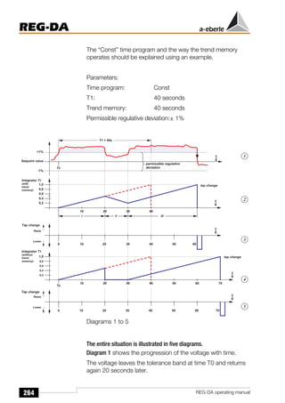
![275
REG-DA
REG-DA operating manual
15.9.5 Description of the regulation programs
15.9.5.1 The ∆I sin ϕ procedure
Functional principle:
The value of the reactive current should be the same value, IbA
= IbB = IbC = ... , for each of the transformers operating in
parallel A, B, C,... .
If this condition is fulfilled, the circulating reactive current is zero.
Area of application:
Parallel operation on a busbar with a maximum of 10
transformers with nearly equal nominal power, nearly equal
short circuit voltage and the same switching group.
The tap-change increments may differ and the cos ϕ in the
network can take any values requested.
Prerequisites:
The short circuit voltages, Uk of the transformers operating in
parallel should only differ by a small amount:
(0.90 ukn-1 ukn 1.10 ukn-1) and the nominal powers should be
approximately the same.
The ∆I sin ϕ [S] program is available when transformers with
different nominal powers are used.
Parameters to be entered:
➪ Permissible circulating current (depends on the change in
the circulating reactive current ∆Icirc sin ϕ = Ib** - Ib* per
tap-change of the assigned transformer)
➪ Group list of the relays/transformers (addresses of relays
which can be activated via the menu, ParaGramer or a
binary signal, that control transformers that are operating in
parallel on a busbar)
➪ Maximum tap difference between the transformers
(SETUP 5, Add-On 6)](https://image.slidesharecdn.com/re-hfy3-3130-ved-080-ele-man-0006atrainingmanual-230922232824-a612d134/85/ABB-Training-Manual-pdf-396-320.jpg)
![300
REG-DA
REG-DA operating manual
17 Symbols and their Definition
Symbol Definition
I [%] Upper limit value of the current
(of the transformer)
I [%] Lower limit value of the current
(of the transformer)
U [%] Upper limit value of the voltage
(of the transformer)
U [%] Lower limit value of the voltage
(of the transformer)
∆I [A] Difference between 2 current values
∆U [V] Difference between 2 voltage levels
AA1 ... AAn Analogue output (mA)
AI1 ... AIn Analogue input (mA)
BO1 ... BO Binary output
(USt. : 10 V ... 50 V)
E1 ... En Binary input
(USt. : 48 V ... 230 V)
Ft [1] Time factor for time behaviour
of the Relay for Voltage Control
Transformer Monitoring
I1n [A] Nominal value of the primary
current transformer
(of the transformer)
I2n [A] Nominal value of the secondary
current transformer
(of the transformer)
Icirc [A] Circulating current in parallel-
switched transformers
Icirc sin ϕ [A] Reactive component of the
circulating current Icirc
I [A] Delivered load current
of the transformer](https://image.slidesharecdn.com/re-hfy3-3130-ved-080-ele-man-0006atrainingmanual-230922232824-a612d134/85/ABB-Training-Manual-pdf-421-320.jpg)
![301
REG-DA
REG-DA operating manual
I sin ϕ = Ib [A] Reactive component of the load
current
(short reactive current Ib)
Kni [1] Transformer mounting ratio of the
current transformer
Knu [1] Transformer mounting ratio voltage
transformer
R1 ... Rn Relay outputs
S [VA] Apparent power
Sn [VA] Nominal power of the transformer
St [%] Gradient of the Uf/I characteristic
line
Gnom [%] Nominal value of the gradient
of the Uf/I characteristic line
tb [s] Basic time; standard value for
tb = 30 s for Xwb = 1 %
tV [s] Reaction delay of a control
command
U1N [kV] Nominal value of the voltage
transformer
primary
U2N [V] Nominal value of the voltage
transformer
secondary
Uf [V] Voltage drop (amount) on the
line
Uf [V] Voltage drop (pointer) on the
line
Uact Actual value of the voltage
uk [%] Short-circuit voltage of the
transformer; component of the
nominal voltage, which operates in
the nominal current in the short-
circuited secondary winding
Uset Setpoint value of the voltage
UT [V] Voltage at the transformer
(r.m.s value)
Symbol Definition](https://image.slidesharecdn.com/re-hfy3-3130-ved-080-ele-man-0006atrainingmanual-230922232824-a612d134/85/ABB-Training-Manual-pdf-422-320.jpg)
![302
REG-DA
REG-DA operating manual
UV [V] Voltage at the consumer
(r.m.s value)
W [V] Command variable (XR + XK)
X [V] Actual value of the command
variable
(of the voltage)
X0 Reference value for limit values
(setpoint value or 100/110 V)
Xd [V, %] Regulation difference (negative
regulative deviation: Xd = - Xw)
XK [V] Correction quantity (Uf)
XR [V] Setpoint value, set on the Relay for
Voltage Control Transformer
Monitoring
XR100 [ V ]: Setpoint that is defined as the
100% value.
Xw [%] (relative) Regulative deviation
[(X - W) / W] 100 %
Xw [V] (absolute) Regulative deviation (X - W)
Xwb [%] Rated relative regulative deviation;
control commands are activated
when Xwb = 1%
Xwz [%] Permissible regulative deviation, set
on the Relay for Voltage Control
Transformer Monitoring; indication
in ± n% in relation to W
Y [1] Correcting variable 1 tap
Yh [1] Setting range
number of tap-changes
Z [V] Influencing variable
Symbol Definition](https://image.slidesharecdn.com/re-hfy3-3130-ved-080-ele-man-0006atrainingmanual-230922232824-a612d134/85/ABB-Training-Manual-pdf-423-320.jpg)


![Transformer Repair Workshop Report [EEE]](https://cdn.slidesharecdn.com/ss_thumbnails/transformerrepairworkshopeee-140621072318-phpapp01-thumbnail.jpg?width=640&height=640&fit=bounds)


