Downloaded 609 times


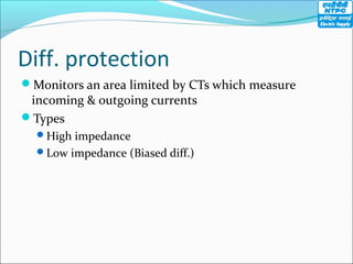
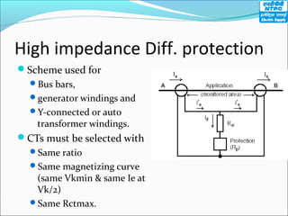
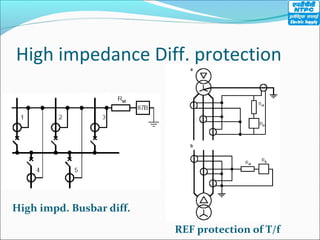
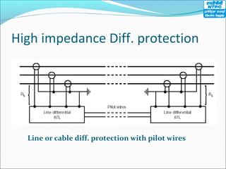
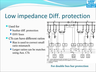
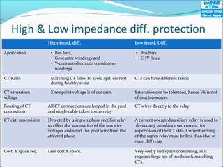

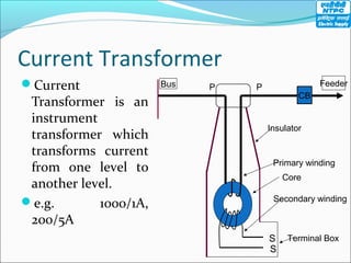

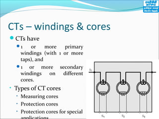
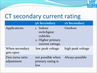
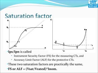
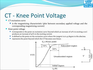
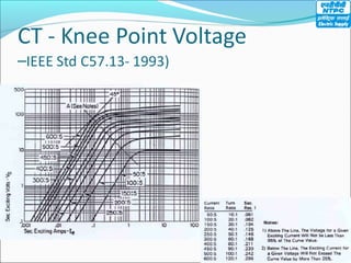
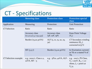
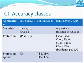
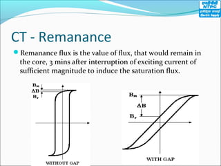
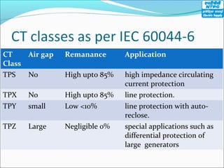
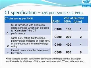


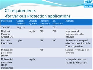
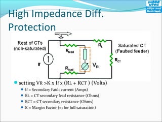
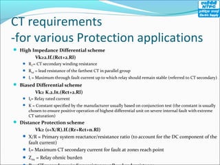
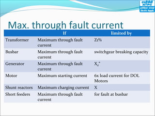

This document discusses various protection schemes and current transformer design requirements to support them. It covers overcurrent, unit, differential, and distance protection. It describes high and low impedance differential protection and the differences in their current transformer requirements. Key factors discussed are current transformer knee point voltage, ratio, burden, and saturation performance for different applications like busbar, generator, and line protection.


