The document provides an overview of engineering graphics and drawings. It discusses how graphics are used to effectively communicate technical information through diagrams and illustrations. The summary includes:
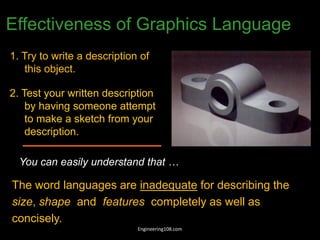
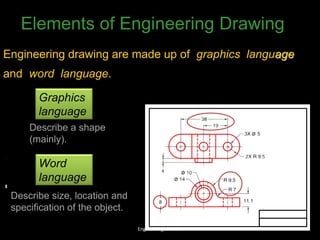
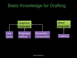
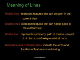
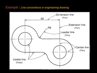
1) Engineering drawings use lines and geometric shapes to represent objects through different views and perspectives in a standardized way. This graphical language allows for clear and concise communication.
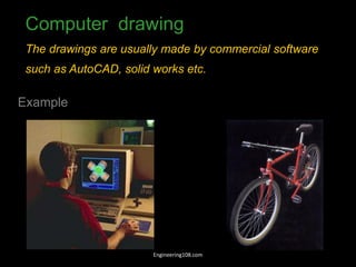
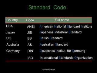
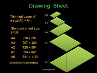
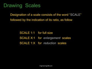
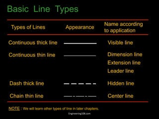
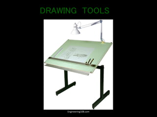
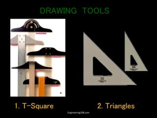
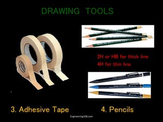
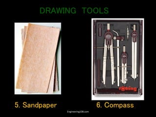
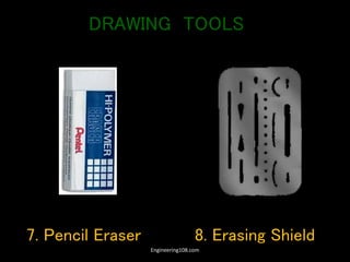
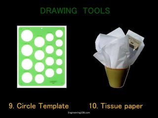
2) Traditional and computer-aided drawing tools and methods are used to precisely construct drawings according to international standards for scale, layout and line types.
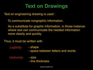
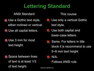
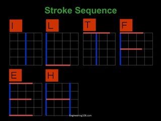
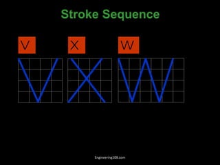
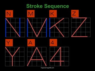
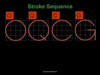
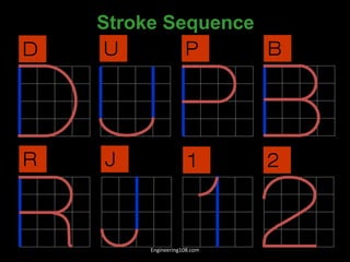
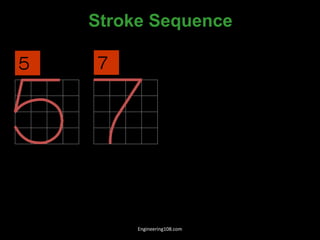
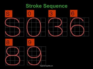
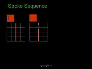
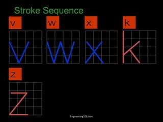
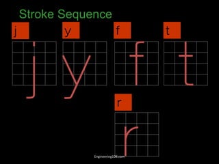
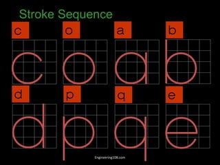
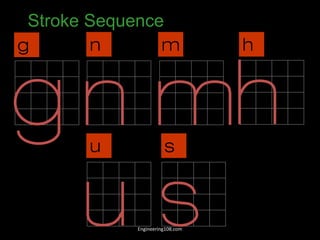
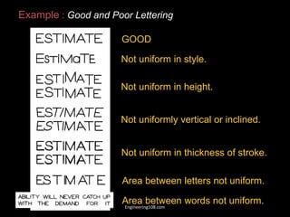
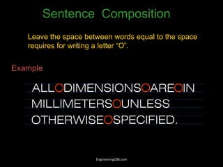
3) Effective lettering and annotation is important for conveying additional details and specifications in a uniform and legible manner on drawings.


![W1-Introduction to ED [Autosaved].pptx](https://cdn.slidesharecdn.com/ss_thumbnails/w1-introductiontoedautosaved-221025152231-90341e07-thumbnail.jpg?width=640&height=640&fit=bounds)


