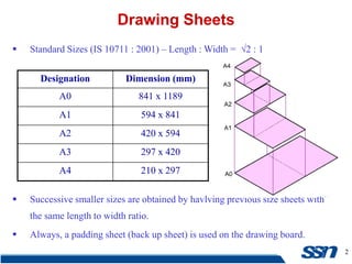
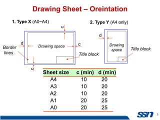
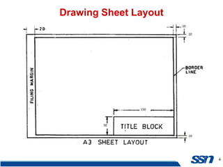
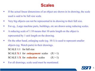
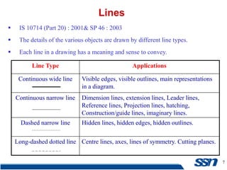
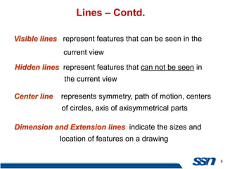
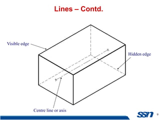
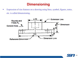
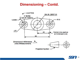
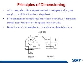
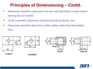
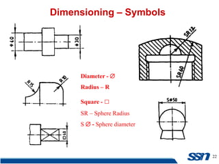
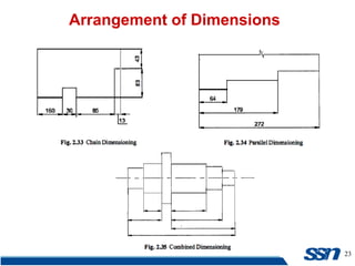
2. 2
Standard Sizes (IS 10711 : 2001) – Length : Width = √2 : 1
Successive smaller sizes are obtained by havlving previous size sheets with
the same length to width ratio.
Always, a padding sheet (back up sheet) is used on the drawing board.
Drawing Sheets
Designation Dimension (mm)
A0 841 x 1189
A1 594 x 841
A2 420 x 594
A3 297 x 420
A4 210 x 297
3. 3
Drawing Sheet – Oreintation
Drawing space Drawing
space
Title block
d
d
c
c
c
Border
lines
1. Type X (A0~A4) 2. Type Y (A4 only)
Title block
Sheet size c (min) d (min)
A4 10 20
A3 10 20
A2 10 20
A1 20 25
A0 20 25
6. 6
If the actual linear dimensions of an object are shown in its drawing, the scale
used is said to be full size scale.
Very big objects can not be represented in its drawing to their full size.
For eg., Large machine parts, buildings, etc are drawn using reducing scales.
A reducing scale of 1:10 means that 10 units length on the object is
represented by 1 unit length on the drawing.
On the other hand, enlarging scale (eg. 10:1) is used to represent smaller
objects (eg. Watch parts) in their drawings.
SCALE 1:1 for full size
SCALE X:1 for enlargement scales (X > 1)
SCALE 1:X for reduction scales (X > 1)
For all drawings, scale used must be mentioned.
Scales
7. 7
IS 10714 (Part 20) : 2001& SP 46 : 2003
The details of the various objects are drawn by different line types.
Each line in a drawing has a meaning and sense to convey.
Lines
Line Type Applications
Continuous wide line Visible edges, visible outlines, main representations
in a diagram.
Continuous narrow line Dimension lines, extension lines, Leader lines,
Reference lines, Projection lines, hatching,
Construction/guide lines, imaginary lines.
Dashed narrow line Hidden lines, hidden edges, hidden outlines.
Long-dashed dotted line Centre lines, axes, lines of symmetry. Cutting planes.
8. 8
Lines – Contd.
Visible lines represent features that can be seen in the
current view
Hidden lines represent features that can not be seen in
the current view
Center line represents symmetry, path of motion, centers
of circles, axis of axisymmetrical parts
Dimension and Extension lines indicate the sizes and
location of features on a drawing
10. 10
Precedence of Lines:
When a visible line coincides with a hidden line or centre line, draw the
visible line. Also, extend the centre line beyond the outlines of the view.
When a hidden line coincides with a centre line, draw the hidden line.
When a visible line coincides with a cutting plane line, draw the visible
line.
When a centre line coincides with a cutting plane line, draw the centre
line and show the cutting plane line outside the outlines of the view.
Lines – Contd.
11. 11
Lettering is defined as writing of titles, sub-titles, dimensions, etc.
Main features – legibility, uniformity and rapidity of execution.
Use of drawing instruments for lettering consumes more time.
Hence, Lettering should be done freehand with speed.
BIS and ISO Conventions - IS9609 (Part 0) : 2001 and SP 46 : 2003
Lettering in a drawing should use upper-case (CAPITALS).
Lower-case letters are used in writing the abbreviations like mm, etc.
Size of letters – height of the capital letters and numerals.
Lettering
16. 16
All necessary dimensions required to describe a component clearly and
completely shall be written in drawings directly.
Each feature shall be dimensioned only once in a drawing, i.e. dimensions
marked in one view need not be repeated in another view.
Dimension should be placed on the view where the shape is best seen.
Principles of Dimensioning
17. 17
Dimensions should be expressed in one unit only (preferably in mm) without
showing the unit symbol.
As far as possible, dimensions should be placed outside the view.
Dimensions should be taken from visible outlines rather than from hidden
lines.
Principles of Dimensioning – Contd.
18. 18
No gap should be left between the feature and the start of the extension line.
Crossing of centre lines should be done by a long dash and not a short dash.
Principles of Dimensioning – Contd.
20. 20
Dimensioning – Methods.
Aligned method – dimensions should be placed parallel to and
above their dimension line (preferably at the centre).
21. 21
Dimensioning – Methods.
Uni-directional method – dimensions should be placed so that they can be
read from the bottom of the drawing only.
Non-horizontal lines are interrupted, preferably in the middle, for the insertion
of the dimension.