Downloaded 32 times
![2
2 Table of figures
Figure 1 - Various wing design shapes yield different performance [1].................................................. 3
Figure 2 - Wing attach points and wing dihedrals [1].............................................................................. 3
Figure 3 - Typical transport and fighter wing [2]..................................................................................... 4
Figure 4 - Externally braced wings [1]..................................................................................................... 4
Figure 5 - Wing structure [1].................................................................................................................... 5
Figure 6 - Metal wing spar shapes [1]...................................................................................................... 6
Figure 7 - Wing ribs constructed of wood. A – truss type web. B – truss web ribs with a continuous
gusset. C – rib with lighten plywood web [1] .......................................................................................... 6
Figure 8 - The skin is an integral load carrying part of a stressed skin design [1]................................... 7
Figure 9 - Fuel is carried in the wings [1]................................................................................................ 7
Figure 10 - Three spar wing - all bending materials concentrated at the spar cap [2] ............................. 8
Figure 11 - Typical wing skin stringer panels [2] ...................................Error! Bookmark not defined.
Figure 12 - Different wing box structure [2]............................................................................................ 9
Figure 13 - Typical spar cap sections [1] ............................................................................................... 10
Figure 14 - Typical spar construction [1]............................................................................................... 10
Figure 15 - Typical spar configurations [1] ........................................................................................... 10
Figure 16 - A fail-safe spar with a riveted spar web [2] ........................................................................ 11
Figure 17 - Comparison of rib direction (rectangular box) [1] .............................................................. 11
Figure 18 - Typical rib construction [1]................................................................................................. 11
Figure 19 - Wing root joint - spliced plate [1] ....................................................................................... 12
Figure 20 - A wing leading edge formed from honeycomb material bonded to the aluminium spar
structure [2] ............................................................................................................................................ 13
Figure 21 - Determination of rib spacing by structural weight comparison [1]..................................... 14](https://image.slidesharecdn.com/wingboxdesign-191127023122/75/PRELIMINARY-DESIGN-APPROACH-TO-WING-BOX-LAYOUT-AND-STRUCTURAL-CONFIGURATION-3-2048.jpg)
![3
3 Introduction
3.1 Aircraft wings
Aircraft wing design is different according to flight characteristics and flight conditions. Different types
of wing designs are in figure 1-4.
Figure 1 - Various wing design shapes yield different performance [3]
Figure 2 - Wing attach points and wing dihedrals [3]](https://image.slidesharecdn.com/wingboxdesign-191127023122/75/PRELIMINARY-DESIGN-APPROACH-TO-WING-BOX-LAYOUT-AND-STRUCTURAL-CONFIGURATION-4-2048.jpg)
![4
Figure 3 - Typical transport and fighter wing [1]
Figure 4 - Externally braced wings [3]](https://image.slidesharecdn.com/wingboxdesign-191127023122/75/PRELIMINARY-DESIGN-APPROACH-TO-WING-BOX-LAYOUT-AND-STRUCTURAL-CONFIGURATION-5-2048.jpg)
![5
3.2 Function of the wings
3.2.1 Generate lift
In the fixed-wing aircraft, mainly, there are two wings beside the fuselage. The wings provide
lift force to get lifted in the air. The shape and size of the wing depend on the size and weight of the
aircraft as heavier aircrafts need higher lift force, hence need bigger wing area.
3.2.2 Store fuel
Apart from the main function, aircraft wing provide space to store aviation fuel. 60-90% of the
total fuel load is stored within the wing section.
3.2.3 Powerplant and landing gear mount
Also, main powerplants of some aircrafts are attached to the wing sections. In modern
commercial aircrafts, retractable landing gears are also mounted in the wing root area.
3.2.4 Control surface mounting facility
Control surfaces that need to handle the aircraft in the air is attached to the wings. So that, there
are several key functions of the wing apart from the lift generation.
Figure 5 - Wing structure [3]](https://image.slidesharecdn.com/wingboxdesign-191127023122/75/PRELIMINARY-DESIGN-APPROACH-TO-WING-BOX-LAYOUT-AND-STRUCTURAL-CONFIGURATION-6-2048.jpg)
![6
3.3 Primary structural components of the wing
3.3.1 Wing spar
Wing spars are the principal structural elements in an aircraft wing. They are placed parallel to
the lateral axis from the fuselage toward the wing tip. Basically, shear load of the wing is carried by the
wing spars. Depending on the design criteria, they are made with metal, wood or composite materials.
Currently, most of the wing spars are made with solid extruded aluminium or aluminium extrusions
riveted together to form a spar.
3.3.2 Wing ribs
They are the structural components that use to make the framework of the wing. Mainly they
placed from leading edge to the trailing edge component. Ribs give the shape for the wing. Mainly ribs
act as intermediate component to transfer load from the skin and stringers to the spars and distribute the
load to the overall structure. Some ribs are named to reflect their unique properties or operations such as
false rib, wing butt ribs
3.3.3 Wing skin
Wing is designed to carry some part of the flight and ground loads combining with spars and
ribs. These types of skins are called as stressed-skin designs. Basically, wing skin carries bending
moment. The lower cover is designed to carry tension forces and upper cover is designed to withstand
Figure 6 - Metal wing spar shapes [3]
Figure 7 - Wing ribs constructed of wood. A – truss type web. B – truss web
ribs with a continuous gusset. C – rib with lighten plywood web [3]](https://image.slidesharecdn.com/wingboxdesign-191127023122/75/PRELIMINARY-DESIGN-APPROACH-TO-WING-BOX-LAYOUT-AND-STRUCTURAL-CONFIGURATION-7-2048.jpg)
![7
compression forces so that mainly designed to avoid buckling (Figure 8). Stressed skin aircrafts carry
fuel inside the wing section (Figure 9).
3.3.4 Nacelles
In some aircrafts, engines are mounted on the wings. So that, nacelles are used mainly to house
the engines. Because of that nacelles become part of wing structure.
Figure 9 - Fuel is carried in the wings [3]
Figure 8 - The skin is an integral load carrying part of a stressed skin design [3]](https://image.slidesharecdn.com/wingboxdesign-191127023122/75/PRELIMINARY-DESIGN-APPROACH-TO-WING-BOX-LAYOUT-AND-STRUCTURAL-CONFIGURATION-8-2048.jpg)
![8
4 Selection of structural configuration and materials
4.1 Structural configuration
4.1.1 Wing box
There are several wing box structures as follows
• Thick box beam structure – build up with two or three spars for high aspect ratio wings
• Multi-spar box structure – lower aspect ratio wings with thin wing airfoil
• Dela wing box – mainly used in military aircrafts that reach supersonic speed
There are three fundamental wing construction designs as Monospar, Multispar and Box beam. In
monospar design, there is only one main spar. Ribs are used to get the required wing shape. Additional
false spars in the trailing edge to support control surfaces. There is more than one main spar in the
Multispar design. In the Box beam design, two main longitudinal members with connecting bulkheads
are used to get the shape of the wing (Figure 11).
Calculate the aspect ratio of the wing.
𝑊𝑖𝑛𝑔 𝑎𝑟𝑒𝑎 =
(8+1.5)
2
× 31.7 = 150.575 𝑚2
𝐴𝑅 =
𝑊𝑖𝑛𝑔 𝑠𝑝𝑎𝑛2
𝑊𝑖𝑛𝑔 𝑎𝑟𝑒𝑎
=
31.72
150.575
𝐴𝑅 = 6.67
Considering this aspect ratio value, thick beam, multi spar wing structure is selected as wing box
structure for business jet.
4.1.2 Wing cover
Wing structure is classified according to the deposition of the bending load resistant material as,
• Bending material is concentrated in the spar cap
• Bending material is distributed around the periphery of the profile
• Skin is primarily bending material.
By considering the following advantages and disadvantages, stressed skin, concentrated spar cap design
is selected for the business jet aircraft. Stiffening materials consists of stiffening elements in the spanwise
direction. Semi-monocoque structure is used as structural configuration.
Figure 10 - Three spar wing - all bending materials concentrated at the spar cap [1]](https://image.slidesharecdn.com/wingboxdesign-191127023122/75/PRELIMINARY-DESIGN-APPROACH-TO-WING-BOX-LAYOUT-AND-STRUCTURAL-CONFIGURATION-9-2048.jpg)
![9
4.1.3 Wing spar
When designing the spars, the sectional area should be as large as possible maintaining high local
crippling stress in the cap sections [1]. Different spar construction types are used, and shear web type is
widely used over truss type. Higher strength – weight ratio and higher stiffness in the semi-tension type
beams over truss type. Truss type spars have small redundancy as one member fails, its load carrying
ability will be lost.
I section spar configuration is selected over other configurations by considering the weight
reduction and ease of manufacturability.
Thick box beam structure Multi-spar box structure
Delta wing structures
Figure 11 - Different wing box structure [1]](https://image.slidesharecdn.com/wingboxdesign-191127023122/75/PRELIMINARY-DESIGN-APPROACH-TO-WING-BOX-LAYOUT-AND-STRUCTURAL-CONFIGURATION-10-2048.jpg)
![10
Figure 12 - Typical spar cap sections [1]
Figure 13 - Typical spar construction [1]
Figure 14 - Typical spar configurations [1]](https://image.slidesharecdn.com/wingboxdesign-191127023122/75/PRELIMINARY-DESIGN-APPROACH-TO-WING-BOX-LAYOUT-AND-STRUCTURAL-CONFIGURATION-11-2048.jpg)
![11
4.1.4 Wing ribs
There are several methods of rib arrangements as in the figure 17. From that, conventional rib
arrangement is selected over rib arrangement – parallel to the flight path considering following facts.
• Many disadvantages in (b) arrangement compared with (a) arrangement in structural point of
view.
• Rib length is higher in (b) arrangement so that weight is increased.
• In (b) arrangement, larger riveting is required for the spanwise stiffeners.
Also, Shear web type wing ribs are used over other rib arrangements shown in figure 7.
Figure 15 - A fail-safe spar with a riveted spar web [3]
Figure 16 - Comparison of rib direction (rectangular box) [1]
Figure 17 - Typical rib construction [1]](https://image.slidesharecdn.com/wingboxdesign-191127023122/75/PRELIMINARY-DESIGN-APPROACH-TO-WING-BOX-LAYOUT-AND-STRUCTURAL-CONFIGURATION-12-2048.jpg)
![12
4.1.5 Wing root joint
That part is one of the most critical parts in the wing design. There are two types of wing joint designs
as fixed joint and rotary joints. Here uses fixed joint as there is no need of changing the sweep angle of
the wing. Different wing root fixed joints are listed in the table 1. Considering this, sliced plate
arrangement can be used in the wing joints.
Table 1- Wing root fixed joint types
Figure 18 - Wing root joint - spliced plate [1]](https://image.slidesharecdn.com/wingboxdesign-191127023122/75/PRELIMINARY-DESIGN-APPROACH-TO-WING-BOX-LAYOUT-AND-STRUCTURAL-CONFIGURATION-13-2048.jpg)
![13
4.2 Material selection
4.2.1 Wing cover
Wing cover can be considered as lower and upper covers.
Lower wing cover – loaded primarily with tension. Materials should have higher tensile strength to
density ratio with good fracture toughness and fatigue life. Fatigue strength can be improved with
interference fit fasteners [1].
Upper wing cover – loaded primarily with compression. Material selection highly depends on the wing
configuration. Lowest weight construction of wing cover is thin, multi spar and full depth honeycomb
design. In deeper wings, skin stringer panels become attractive [1].
There are several material types can be used in the wing skin as follows [1].
• Al 7075-T651
• Al 2024-T3
• Ti 6Al-4V
• Composite material
Considering the material cost, fatigue life, fracture toughness Al 2024-T3 is used as upper wing skin and
Al 7075-T651 is used for lower skin. Apart from that, composite material used in wing tip, leading edge
areas and several other parts.
4.2.2 Wing spar
By considering the material and mechanical properties, Al 7075 can use because of higher ultimate
tensile strength and ease of formability.
4.2.3 Wing ribs
Same as the wing spars, Al 7075 material can be used to manufacture wing ribs.
Figure 19 - A wing leading edge formed from honeycomb material bonded to the aluminium
spar structure [3]](https://image.slidesharecdn.com/wingboxdesign-191127023122/75/PRELIMINARY-DESIGN-APPROACH-TO-WING-BOX-LAYOUT-AND-STRUCTURAL-CONFIGURATION-14-2048.jpg)
![14
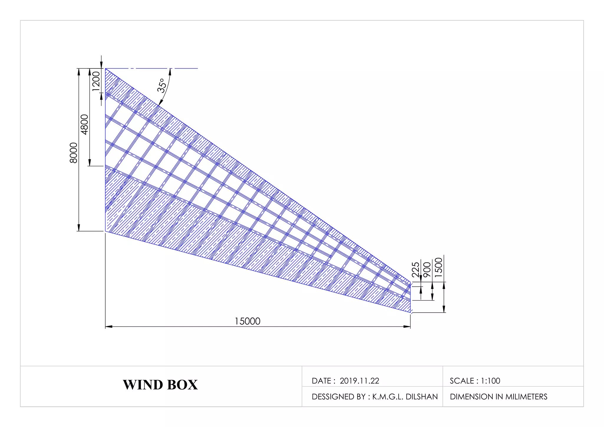
5 Dimension of the wing box
5.1 Main spar
Front spar is located at about 12 - 17% chord. Rear spar at about 55 – 60 % chord. Those locations are
finalized by considering the flight controller positions. As this wing is tapered one, tapered spar can be
used to reduce weight [2].
5.2 Wing ribs
Rib spacing determined by considering weight increment. Higher rib spacing will reduce weight. Those
calculation can be done using following equation.
Ic can be consider as 0.031 m4
for the selected rib geometry and minimum rib space is 400mm. By
considering those factors, 800mm rib spacing can be considered according to the figure 21. There must
be ribs located near control surface hinges.
Figure 20 - Determination of rib spacing by structural weight
comparison [1]](https://image.slidesharecdn.com/wingboxdesign-191127023122/75/PRELIMINARY-DESIGN-APPROACH-TO-WING-BOX-LAYOUT-AND-STRUCTURAL-CONFIGURATION-15-2048.jpg)
![15
6 References
[1] M. C.-Y. Niu, Airframe Structural Design, HONG KONG: HONG KONG CONMILIT PRESS
LTD, 2002.
[2] V. S. Ajith, R. Paramasivam and K. Vidhya, “Study of optimal design of spar beam for the wing
of an aircraft,” IJEDR, vol. 5, no. 3, pp. 179 - 193, 2017.
[3] F. A. ADMINISTRATION, Aviation Maintenance Technician Handbook - Airframe - Volume 1,
Oklahoma City: U.S. Department of Transportation, 2018.
[4] L. News, “Bombardier selling off unique CSeries technology,” LEEHAM NEWS AND
ANALYSIS, 06 MAY 2019. [Online]. Available: https://leehamnews.com/2019/05/03/bjorns-
corner-bombardier-selling-off-unique-cseries-technology/. [Accessed 27 October 2019].
[5] “Aircraft Design - an Open Educational Resource,” Hamburh open online university, 27 May
2017. [Online]. Available: http://hoou.profscholz.de/. [Accessed 27 October 2019].
[6] L. F. Soares, G. Lapa, P. Almeida and B. Pignolati, “Structural Analysis of a wing box,”
International Journal of Engineering Research and Applications, vol. 5, no. 5, pp. 23-31, 2015.](https://image.slidesharecdn.com/wingboxdesign-191127023122/75/PRELIMINARY-DESIGN-APPROACH-TO-WING-BOX-LAYOUT-AND-STRUCTURAL-CONFIGURATION-17-2048.jpg)

The document outlines a preliminary design approach for aircraft wing box layout and structural configuration, covering the essential functions, components, and materials used in wing construction. It discusses the wing's roles in generating lift, fuel storage, and mounting for control surfaces and engines, along with key structural elements like spars, ribs, and skins. Additionally, the document details various design configurations, material selection, and specific dimensions for optimal wing performance.