One of the main challenges for the civil aviation industry is the reduction of its environmental impact by better fuel efficiency by virtue of Structural optimization. Over the past years, improvements in performance and fuel efficiency have been achieved by simplifying the design of the structural components and usage of composite materials to reduce the overall weight of the structure. This paper deals with the weight optimization of transport aircraft with low wing configuration. The Linear static and Normal Mode analysis were carried out using MSc Nastran & Msc Patran under different pressure conditions and the results were verified with the help of classical approach. The Stress and displacement results were found and verified and hence arrived to the conclusion about the optimization of the wing structure.
Design and analysis of undertray diffuser for a formula style racecareSAT Journals
Abstract The advancements in Formula one industry have clearly shown the importance of Aerodynamics and thus it was taken as an opportunity to design and develop a not much widely known aerodynamic component, a diffuser considering the myriad of benefits. This report explains the development of an undertray diffuser for an Formula Student (fsae) car. An undertray Diffuser is just as the front and back wing of race cars an aerodynamic package that generates Downforce. The hard part of designing an aerodynamic package for these cars is their top speed. The faster a car drives the more downforce is going to be generated. The Formula student race cars have a top speed around 130km/h. Due to this low top speed (Formula 1 cars reach top speeds of 370km/h), the wings of the car have to work with lower speeds and have to be larger. The undertray diffuser has to generate as much downforce as possible and as less drag as possible. The working principle of the undertray diffuser is explained later. The air under the undertray diffuser travels faster than on top of the undertray diffuser. When this happens a lower pressure is generated underneath the undertray diffuser and this lower pressure generates downforce. Keywords: Aerodynamics, downforce, speed, pressure.
Morphing Aircraft Technology – New Shapes for Aircraft Wing DesignMani5436
Morphing aircraft are multi-role aircraft that change their external shape substantially to adapt to a changing mission environment during flight.
Morphing poses several unique challenges when the wing loading is high. Very flexible materials are the designer’s first choice because they are easily reshaped.
he current use of multiple aerodynamic devices (such as flaps and slats) represents a simplification of the general idea behind morphing. Traditional control systems (with fixed geometry and/or location) give high aerodynamic performance over a fixed range and for a limited set of flight conditions.
Design, Analysis and Testing of Wing Spar for Optimum WeightRSIS International
Aircraft is a complex mechanical structure with flying capability. The structure of an airframe represents one of the finest examples of a minimum weight design in the field of structural engineering. Surprisingly such an efficient design is achieved by the use of simple “strength-of-material” approach. Aircraft has two major components, which are fuselage and wing. For a wing of an aircraft the primary load carrying ability is required in bending. A typical aluminium material 6082-T6 is chosen for the design. A four-Seater aircraft wing spar design is considered in the current study. Wings of the aircraft are normally attached to the fuselage at the root of the wing. This makes the wing spar beam to behave almost like a cantilever beam. Minimum two spars are considered in the wing design. In a conventional beam design approach one will end up in heavy weight for the spar of the wing. In the current project the spar is considered as a beam with discrete loads at different stations. The design is carried out as per the external bending moment at each station. A finite element approach is used to calculate the stresses developed at each station for a given bending moment. Several stress analysis iterations are carried out for design optimization of the spar beam. Linear static analysis is used for the stress analysis. The spar beam is designed to yield at the design limit load. Weight optimization of the spar will be carried out by introducing lightening cut-outs in the web region. The results from the conventional design approach and the optimized design are compared. Weight saving through the design optimization is calculated. Spar will be a built-up structure. A scale-down model of the spar will be fabricated using aluminium alloy 6082-T6 material. Static testing of the spar will be carried out to validate the design and stress analysis results.
CADmantra Technologies Pvt. Ltd. is one of the best Cad training company in northern zone in India . which are provided many types of courses in cad field i.e AUTOCAD,SOLIDWORK,CATIA,CRE-O,Uniraphics-NX, CNC, REVIT, STAAD.Pro. And many courses
Contact: www.cadmantra.com
www.cadmantra.blogspot.com
www.cadmantra.wix.com
A Presentation About The Introduction Of Finite Element Analysis (With Example Problem) ... (Download It To Get More Out Of It: Animations Don't Work In Preview) ... !
International Journal of Engineering Research and Applications (IJERA) is an open access online peer reviewed international journal that publishes research and review articles in the fields of Computer Science, Neural Networks, Electrical Engineering, Software Engineering, Information Technology, Mechanical Engineering, Chemical Engineering, Plastic Engineering, Food Technology, Textile Engineering, Nano Technology & science, Power Electronics, Electronics & Communication Engineering, Computational mathematics, Image processing, Civil Engineering, Structural Engineering, Environmental Engineering, VLSI Testing & Low Power VLSI Design etc.
Application of Exergy and Taguchi Methodology for a Power Plant under Varying...IJERA Editor
In this study, exergy efficiencies of a thermal power plant under different operating conditions have been investigated. Taguchi method is applied using three factors, namely, ambient temperature, condenser pressure and steam temperature with three levels of each. The operating conditions are planned and are set following orthogonal array of L9 and regression analysis is carried out in order to determine the effects of process parameters on exergy efficiency for the power plant. The correlation between exergy efficiencies and operating parameters are obtained by a 2nd order polynomial regression analysis and compared with the actual results and found to be quite correct having average error is about 1% only.
Extract the ancient letters from decoratedIJERA Editor
Nowadays, large databases of ornaments of the hand-press period are available and need efficient retrieval tools
for history specialists and general users. This article deals with document images analysis. The purpose of our
work is to automatically determine the letter represented in an ornamental letter image. Our process is divided
into two parts: Wavelet transformation: Segmentation of the ornamental letter followed by a recognition step.
The segmentation process uses multi-resolution analysis to filter background decorations followed by
binarisation and morphologic reconstruction of the expected letter.
Analyzing Video Streaming Quality by Using Various Error Correction Methods o...IJERA Editor
Transmission video over ad hoc networks has become one of the most important and interesting subjects of study for researchers and programmers because of the strong relationship between video applications and frequent users of various mobile devices, such as laptops, PDAs, and mobile phones in all aspects of life. However, many challenges, such as packet loss, congestion (i.e., impairments at the network layer), multipath fading (i.e., impairments at the physical layer) [1], and link failure, exist in transferring video over ad hoc networks; these challenges negatively affect the quality of the perceived video [2].This study has investigated video transfer over ad hoc networks. The main challenges of transferring video over ad hoc networks as well as types of errors that may occur during video transmission, various types of video mechanisms, error correction methods, and different Quality of Service (QoS) parameters that affect the quality of the received video are also investigated.
International Journal of Engineering Research and Applications (IJERA) is an open access online peer reviewed international journal that publishes research and review articles in the fields of Computer Science, Neural Networks, Electrical Engineering, Software Engineering, Information Technology, Mechanical Engineering, Chemical Engineering, Plastic Engineering, Food Technology, Textile Engineering, Nano Technology & science, Power Electronics, Electronics & Communication Engineering, Computational mathematics, Image processing, Civil Engineering, Structural Engineering, Environmental Engineering, VLSI Testing & Low Power VLSI Design etc.
Study of Aircraft Wing with Emphasis on Vibration CharacteristicsIJERA Editor
It is essential that the structural stability of the aircraft wings is a major consideration in the design of the aircraft. Many studies are being carried out for the design of the wings across the globe by the researches to strengthen the aircraft wings for steady and sturdy structures for dynamic conditions. The design of the aircraft wing using NACA standards is been discussed in this work. The wing analysis is carried out by using computer numerical analysis tool, viz., CAD/CAE and CFD. The necessary inputs for carrying out the structural analysis with emphasis on the vibration are obtained by CFD analysis. The deformation of the wing structures are investigated with respect to the standard airflow velocity. The velocity of air at the inlet is taken as 122 m/s (438 km/h), considering service ceiling of 7625 m at moderate temperature. The modal analysis is considered to analyse the wing to determine the natural frequency for vibration characteristics of the wing structure. The study of the effect of the stresses and deformations of the wing structure on the vibration characteristics of the wing is carried out to understand the effect of stress on natural frequency of the aircraft wing structure. Hence it is possible to correlate the effect of wind pressure on the vibration of the wing structure for particular design of the wing (NACA). The CFD results revealed that the pressure on the upper surface of the wing for all the wing section planes (butt planes-BL) is less, about -4.97e3N/mm2, as compared to the pressure on the lower surface, about 1.08e4 N/mm2, which satisfy the theory of lift generation. The pre-stressed modal analysis shows the correlation of the stress, deformation and the corresponding mode of vibration. It is found that the maximum deformation of 17.164 mm is corresponding to the modal frequency of 179.65 Hz which can be considered as design frequency of the wing structure. However the fundamental natural frequency of the wing structure is 10.352 Hz for the deformation of 11.383 mm.
A Brief Study, Research, Design, Analysis on Multi Section Variable Camber WingIJERA Editor
Minimizing fuel consumption is one of the major concerns in the aviation industry. In the past decade, there
have been many attempts to improve the fuel efficiency of aircraft. One of the methods proposed is to vary the
lift-to-drag ratio of the aircraft in different flight conditions. To achieve this, the wing of the airplane must be
able to change its configuration during flight, corresponding to different flight regimes.In the research presented
in this thesis, the aerodynamic characteristics of a multisection, variable camber wing were investigated. The
model used in this research had a 160mm chord and a 200mm wingspan, with the ribs divided into 4 sections.
Each section was able to rotate approximately 5 degrees without causing significant discontinuity on the wing
surface. Two pneumatic actuators located at the main spar were used to morph the wing through mechanical
linkages. The multi-section variable camber wing model could provide up to 10 percent change in camber from
the baseline configuration, which had a NACA0015 section.The wing was tested in the free-jet wind tunnel at
three different Reynolds numbers: 322000, 48000, and 636000. Static tests were performed to obtain lift and
drag data for different configurations. Two rigid wings in baseline and camber configuration were built and
tested to compare the test data with variable camber wing. The wind tunnel test results indicated that the multisection
variable camber wing provided a higher lift than the rigid wing in both configurations whereas high drag
was also generated on the variable camber wing due to friction drag on the wing skin. The larger drag value
appeared on variable camber wing in baseline configuration than in cambered configuration resulting in lower
lift-to-drag ratio as compared to the baseline rigid wing whereas the variable camber wing in cambered
configuration had higher lift-to-drag ratio than the cambered rigid wing.
Optimizationof fuselage shape for better pressurization and drag reductioneSAT Journals
Abstract
The fuselage of any aircraft is essentially to accommodate the payload. It is normally not as streamlined as the wing. Cabin pressurization has been a major concern in the manufacturing of aircrafts. Generally, a cylindrical shape is preferred from a pressurization point of view as it has a higher strength and weighs less too. On the other hand, a sphere is considered as the best pressure vessel among all the shapes, but, sphere being a bluff body is not suitable for carrying payloads. On this note, a cylinder is considered to be better than a sphere to carry the payload and mainly to achieve a streamlined flow. In this paper, the shape chosen is a combination of the sphere and the cylinder to achieve optimum results for pressurization as well as a better streamlined flow. Our prime aim is to convert this bluff body into something more efficient and useful, rather than only for carrying the payload. We have focused basically on two details viz. 1) Better Pressurization and 2) to assist in minimizing the drag, thereby increasing the overall lift of the aircraft and hence increasing the fuel efficiency. The proposed fuselage structure was designed in CATIA V5 software and structural analyses were done in Auto-Desk Multi-Physics software. As a result, a better structural load capacity was found. A load of 10 N/mm2 was applied on both the bodies under consideration (cylinder and ellipse) having the same material, surface area, volume and weight. For the proposed elliptical design, 78% reduction in the minimum stress value and 10% reduction in the maximum stress value were noticed.
Keywords: Fuselage, Lifting Fuselage, Drag Reduction, Pressurization, Hoop Stress, Multi body design, Toroidal Shells, Multi-cylinder, Channel Propeller Configuration, Carbon Fiber, Graphite Fiber, Stabilization and Carbonization.
International Journal of Engineering Research and DevelopmentIJERD Editor
Electrical, Electronics and Computer Engineering,
Information Engineering and Technology,
Mechanical, Industrial and Manufacturing Engineering,
Automation and Mechatronics Engineering,
Material and Chemical Engineering,
Civil and Architecture Engineering,
Biotechnology and Bio Engineering,
Environmental Engineering,
Petroleum and Mining Engineering,
Marine and Agriculture engineering,
Aerospace Engineering.
The International Journal of Engineering & Science is aimed at providing a platform for researchers, engineers, scientists, or educators to publish their original research results, to exchange new ideas, to disseminate information in innovative designs, engineering experiences and technological skills. It is also the Journal's objective to promote engineering and technology education. All papers submitted to the Journal will be blind peer-reviewed. Only original articles will be published.
The papers for publication in The International Journal of Engineering& Science are selected through rigorous peer reviews to ensure originality, timeliness, relevance, and readability.
CFD Simulation of By-pass Flow in a HRSG module by R&R Consult.pptxR&R Consult
CFD analysis is incredibly effective at solving mysteries and improving the performance of complex systems!
Here's a great example: At a large natural gas-fired power plant, where they use waste heat to generate steam and energy, they were puzzled that their boiler wasn't producing as much steam as expected.
R&R and Tetra Engineering Group Inc. were asked to solve the issue with reduced steam production.
An inspection had shown that a significant amount of hot flue gas was bypassing the boiler tubes, where the heat was supposed to be transferred.
R&R Consult conducted a CFD analysis, which revealed that 6.3% of the flue gas was bypassing the boiler tubes without transferring heat. The analysis also showed that the flue gas was instead being directed along the sides of the boiler and between the modules that were supposed to capture the heat. This was the cause of the reduced performance.
Based on our results, Tetra Engineering installed covering plates to reduce the bypass flow. This improved the boiler's performance and increased electricity production.
It is always satisfying when we can help solve complex challenges like this. Do your systems also need a check-up or optimization? Give us a call!
Work done in cooperation with James Malloy and David Moelling from Tetra Engineering.
More examples of our work https://www.r-r-consult.dk/en/cases-en/
Cosmetic shop management system project report.pdfKamal Acharya
Buying new cosmetic products is difficult. It can even be scary for those who have sensitive skin and are prone to skin trouble. The information needed to alleviate this problem is on the back of each product, but it's thought to interpret those ingredient lists unless you have a background in chemistry.
Instead of buying and hoping for the best, we can use data science to help us predict which products may be good fits for us. It includes various function programs to do the above mentioned tasks.
Data file handling has been effectively used in the program.
The automated cosmetic shop management system should deal with the automation of general workflow and administration process of the shop. The main processes of the system focus on customer's request where the system is able to search the most appropriate products and deliver it to the customers. It should help the employees to quickly identify the list of cosmetic product that have reached the minimum quantity and also keep a track of expired date for each cosmetic product. It should help the employees to find the rack number in which the product is placed.It is also Faster and more efficient way.
NO1 Uk best vashikaran specialist in delhi vashikaran baba near me online vas...Amil Baba Dawood bangali
Contact with Dawood Bhai Just call on +92322-6382012 and we'll help you. We'll solve all your problems within 12 to 24 hours and with 101% guarantee and with astrology systematic. If you want to take any personal or professional advice then also you can call us on +92322-6382012 , ONLINE LOVE PROBLEM & Other all types of Daily Life Problem's.Then CALL or WHATSAPP us on +92322-6382012 and Get all these problems solutions here by Amil Baba DAWOOD BANGALI
#vashikaranspecialist #astrologer #palmistry #amliyaat #taweez #manpasandshadi #horoscope #spiritual #lovelife #lovespell #marriagespell#aamilbabainpakistan #amilbabainkarachi #powerfullblackmagicspell #kalajadumantarspecialist #realamilbaba #AmilbabainPakistan #astrologerincanada #astrologerindubai #lovespellsmaster #kalajaduspecialist #lovespellsthatwork #aamilbabainlahore#blackmagicformarriage #aamilbaba #kalajadu #kalailam #taweez #wazifaexpert #jadumantar #vashikaranspecialist #astrologer #palmistry #amliyaat #taweez #manpasandshadi #horoscope #spiritual #lovelife #lovespell #marriagespell#aamilbabainpakistan #amilbabainkarachi #powerfullblackmagicspell #kalajadumantarspecialist #realamilbaba #AmilbabainPakistan #astrologerincanada #astrologerindubai #lovespellsmaster #kalajaduspecialist #lovespellsthatwork #aamilbabainlahore #blackmagicforlove #blackmagicformarriage #aamilbaba #kalajadu #kalailam #taweez #wazifaexpert #jadumantar #vashikaranspecialist #astrologer #palmistry #amliyaat #taweez #manpasandshadi #horoscope #spiritual #lovelife #lovespell #marriagespell#aamilbabainpakistan #amilbabainkarachi #powerfullblackmagicspell #kalajadumantarspecialist #realamilbaba #AmilbabainPakistan #astrologerincanada #astrologerindubai #lovespellsmaster #kalajaduspecialist #lovespellsthatwork #aamilbabainlahore #Amilbabainuk #amilbabainspain #amilbabaindubai #Amilbabainnorway #amilbabainkrachi #amilbabainlahore #amilbabaingujranwalan #amilbabainislamabad
Sachpazis:Terzaghi Bearing Capacity Estimation in simple terms with Calculati...Dr.Costas Sachpazis
Terzaghi's soil bearing capacity theory, developed by Karl Terzaghi, is a fundamental principle in geotechnical engineering used to determine the bearing capacity of shallow foundations. This theory provides a method to calculate the ultimate bearing capacity of soil, which is the maximum load per unit area that the soil can support without undergoing shear failure. The Calculation HTML Code included.
Immunizing Image Classifiers Against Localized Adversary Attacksgerogepatton
This paper addresses the vulnerability of deep learning models, particularly convolutional neural networks
(CNN)s, to adversarial attacks and presents a proactive training technique designed to counter them. We
introduce a novel volumization algorithm, which transforms 2D images into 3D volumetric representations.
When combined with 3D convolution and deep curriculum learning optimization (CLO), itsignificantly improves
the immunity of models against localized universal attacks by up to 40%. We evaluate our proposed approach
using contemporary CNN architectures and the modified Canadian Institute for Advanced Research (CIFAR-10
and CIFAR-100) and ImageNet Large Scale Visual Recognition Challenge (ILSVRC12) datasets, showcasing
accuracy improvements over previous techniques. The results indicate that the combination of the volumetric
input and curriculum learning holds significant promise for mitigating adversarial attacks without necessitating
adversary training.
Overview of the fundamental roles in Hydropower generation and the components involved in wider Electrical Engineering.
This paper presents the design and construction of hydroelectric dams from the hydrologist’s survey of the valley before construction, all aspects and involved disciplines, fluid dynamics, structural engineering, generation and mains frequency regulation to the very transmission of power through the network in the United Kingdom.
Author: Robbie Edward Sayers
Collaborators and co editors: Charlie Sims and Connor Healey.
(C) 2024 Robbie E. Sayers
Water scarcity is the lack of fresh water resources to meet the standard water demand. There are two type of water scarcity. One is physical. The other is economic water scarcity.
Structural Weight Optimization of Aircraft Wing Component Using FEM Approach.
1. Arockia Ruban M Int. Journal of Engineering Research and Applications www.ijera.com
ISSN : 2248-9622, Vol. 5, Issue 6, ( Part -3) June 2015, pp.74-80
www.ijera.com 74 | P a g e
Structural Weight Optimization of Aircraft Wing Component
Using FEM Approach.
Arockia Ruban M, Kaveti Aruna, Puneet Kumar S
Stress Analysis Dept., Jetwings Technologies, Bangalore, India.
Abstract—
One of the main challenges for the civil aviation industry is the reduction of its environmental impact by better
fuel efficiency by virtue of Structural optimization. Over the past years, improvements in performance and fuel
efficiency have been achieved by simplifying the design of the structural components and usage of composite
materials to reduce the overall weight of the structure. This paper deals with the weight optimization of transport
aircraft with low wing configuration. The Linear static and Normal Mode analysis were carried out using MSc
Nastran & Msc Patran under different pressure conditions and the results were verified with the help of classical
approach. The Stress and displacement results were found and verified and hence arrived to the conclusion
about the optimization of the wing structure.
Keywords: Transport Aircraft, Composite materials, Wing Optimization, Stress Analysis, MSc Nastran & Msc
Patran.
I. INTRODUCTION
The wings are airfoil attached to each side of the
fuselage and are the main lifting surfaces that support
the airplane in flight. There are numerous wing
design, size and shape were used by the various
manufacturers. Each fulfils a certain need with respect
to the expected performance for the particular
airplane. Wings may be attached at the top, middle, or
lower portion of the fuselage. These designs are
referred to as high wing, mid wing and low wing
configurations respectively. The number of wings can
also vary, an Airplane with a single set of wing is
referred as a monoplane, while those with two sets
called biplane.
Many high-wing airplanes have external braces or
wing struts which transmit the flight and landing loads
through the struts to the main fuselage structure. Since
the wing struts are usually attached approximately
halfway out on the wing, this type of wing structure is
called semi-cantilever. A few high-wing and most
low-wing airplanes have a full cantilever wing
designed to carry the loads without external struts.
Figure 1: Wing Structure
II. AIR FOIL SELECTION
This section is devoted to the process to
determine airfoil section for a wing. It is appropriate
to claim that the airfoil section is the second most
important wing parameter; after wing planform area.
The airfoil section is responsible for the generation of
the optimum pressure distribution on the top and
bottom surfaces of the wing such that the required lift
is created with the lowest aerodynamic cost (i.e. drag
and pitching moment). Although every aircraft
designer has some basic knowledge of aerodynamics
and airfoils; but to have a uniform starting point, the
concept of airfoil and its governing equations will be
reviewed. The section begins with a discussion on
airfoil selection or airfoil design. Then basics of
airfoil, airfoil parameters and most important factor
on airfoil section will be presented. A review of
NACA4 - the predecessor of the present NASA5-
airfoils will be presented later, since the focus in this
section is on the airfoil selection. The criteria for
airfoil selection will be introduced and finally the
procedure to select the best airfoil is introduced. The
section will be ended with a fully solved example to
select an airfoil for a candidate wing.
III. AIR FOIL DESIGN
The primary function of the wing is to generate lift
force; this will be generated by a special wing cross
section called air foil. Wing is a three dimensional
component, while the airfoil is two dimensional
section. Because of the airfoil section, two other
outputs of the airfoil and consequently the wing are
drag and pitching moment. The wing may have a
constant or a non-constant cross-section across the
wing. There are two ways to determine the wing air
foil section:
RESEARCH ARTICLE OPEN ACCESS
2. Arockia Ruban M Int. Journal of Engineering Research and Applications www.ijera.com
ISSN : 2248-9622, Vol. 5, Issue 6, ( Part -3) June 2015, pp.74-80
www.ijera.com 75 | P a g e
1. Airfoil design
2. Airfoil selection
The design of the airfoil is a complex and time
consuming process and needs expertise in
fundamentals of aerodynamics at graduate level. Since
the airfoil needs to be verified by testing it in a wind
tunnel, it is expensive too. Large aircraft production
companies such as Boeing and Airbus have sufficient
human experts (aerodynamicists) and budget to design
their own airfoil for every aircraft but small aircraft
companies, experimental aircraft producers and
homebuilt manufacturers do not afford to design their
airfoils. Instead they select the best airfoil among the
current available airfoils that are found in several
books or websites.
IV. WING CALCULATION
1) LIFT COEFFICIENT
CLmax = 2×W/ ρ× (VSTALL)2×S
Where,
CLmax =Coefficient of lift
W =Maximum takeoff weight(Kg)
VSTALL =Cruise speed x0.25(Km/h)
S =Wing area(m^2)
ρ =Density(Kg/m^3)
2) CHORD LENGTH
C=S/b
Where,
C = Chord length(m)
S = Wing area(m^2)
b = Wing span(m)
3) INDUCED DRAG CO EFFICIENT
CDi = CL2 / (π×e×AR)
Where,
e = Oswald efficiency factor
AR = Aspect Ratio
4) OSWALD EFFICIENCY FACTOR
e = 4.61(1-0.045AR0.68) (cos(Λ LE))0.15-3.1
Where,
ΛLE =sweep back angle
5) PROFILE DRAG CO EFFICIENT
CDo = Cfe× (Swef / Sref)
Where,
Cfe = Equivalent skin friction co efficient
Swef / Sref =Wetted area ratios
6) TOTAL DRAG CO EFFICIENT
CD = CDo + CDi
Where,
CDi = Induced drag co efficient
CDo = Profile drag co efficient
7) ROOT CHORD
Croot = 2×S / b*(1+ƛ)
Where,
ƛ = Taper ratio
8) TIP CHORD
Ctip = ƛ×Croot
Where,
Ctip =Tip chord
Croot = Root chord
9) EXPOSED WING SPAN
Semi span =b/2
Table 1: Wing Design Parameters
SL.NO
Wing Design
Parameters
Value
1 Lift co-efficient 1.32
2 Chord length 4.28 m
3
Induced Drag Co-
efficient
0.106
4
Oswald Efficiency
Factor
0.65
5
Profile Drag Co
Efficient
0.016
6 Total Drag Co Efficient 0.122
7 Root Chord 6.436 m
8 Tip Chord 2.117 m
9 Exposed Wing Span 17.15 m
10 Swept back angle 20°
V. DESIGN METHODOLOGY
A swept back wing is a type of aircraft wing
configuration where, the root of the wing is lower
than the wing tip, when the aircraft is seen from the
front along the horizontal axis. Dihedral contributes
positively to the stability of the aircraft along the roll-
axis (spiral mode). As the aircraft bank, the swept
back wing tends to roll the aircraft and helps to restore
indirectly the wing level.
To develop 3D model Catia software is used
CATIA (Computer Aided three Dimensional
application) which is design software developed by
Dassaults systems to meet the complicated design
requirements in the field of Aerospace and
Automotive. Here we design swept back wing and
legs separately in CATIA. CATIA was developed for
Boeing later due to its advantage many other
organizations used.
3. Arockia Ruban M Int. Journal of Engineering Research and Applications www.ijera.com
ISSN : 2248-9622, Vol. 5, Issue 6, ( Part -3) June 2015, pp.74-80
www.ijera.com 76 | P a g e
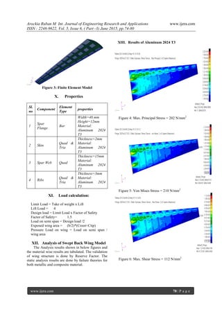
Figure 2: 3D model of Wing Structure
VI. MATERIALS USED FOR THE
CONSTRUCTION OF SWEPT BACK
WING
A. Al ALLOY
Alloys composed of mostly of Aluminum have
been very important in aerospace manufacturing
since the introduction of metals in the aircraft.
Aluminum alloys are light weight and has high
strength. Aluminum alloys have good thermal
strength. The most commonly used Aluminum
alloys for airframe construction are precipitation
hardening alloys in 2XXX and 7XXX series.
B. 2XXX SERIES Al ALLOYS
This series Al alloys contains copper, manganese,
magnesium and zinc. These alloys have low crack
growth rates and better fatigue performance. These
are used on the lower wings and body skin of the
aircraft.
C. 7XXX Al ALLOYS
This alloy consists of aluminum, zinc and
magnesium. Copper often added to improve stress
corrosion cracking resistance. They are used in
light weight military and civil aircrafts.
Table 2: Aluminum 2024 T3 Mechanical Property
D. ADVANTAGES OF ALUMINIUM
1. Aluminum combined with an appropriate alloy
ensures steel durability.
2. It may be easily formed in the course of all
machining processes, such as rolling, embossing,
forging and die-casting.
3. Aluminum structures have considerable insulation
properties securing from air and light activity
4. Such structures are light, which facilitates
assembly and transportation.
5. Aluminum has a natural anti-corrosion layer
which efficiently protects from environmental
influences.
6. Aluminum requires little energy required in the
processing process. Recycling saves 95% of the
energy.
7. Aluminum as a resource is 100% recyclable.
CRITERIA FOR CHOOSING CFRP
MATERIAL:
The proposed aircraft wing structure is an
innovative concept. The whole wing is fabricated with
CARBON FIBRE REINFORCED PLASTICS
(CFRP). The main advantages in this new design are
very good integration, faster fabrication and assembly,
weight reduction, possibility of thickness variation,
less waste of raw material, higher passenger comfort
level, longer structural life (less sensitive to fatigue),
possibility of larger windows. There are also some
disadvantages, although there are some possible
solutions to overcome these disadvantages. The main
disadvantages are electromagnetic interference, return
of electric current, lightening protection, higher
machinery investments and higher certification costs.
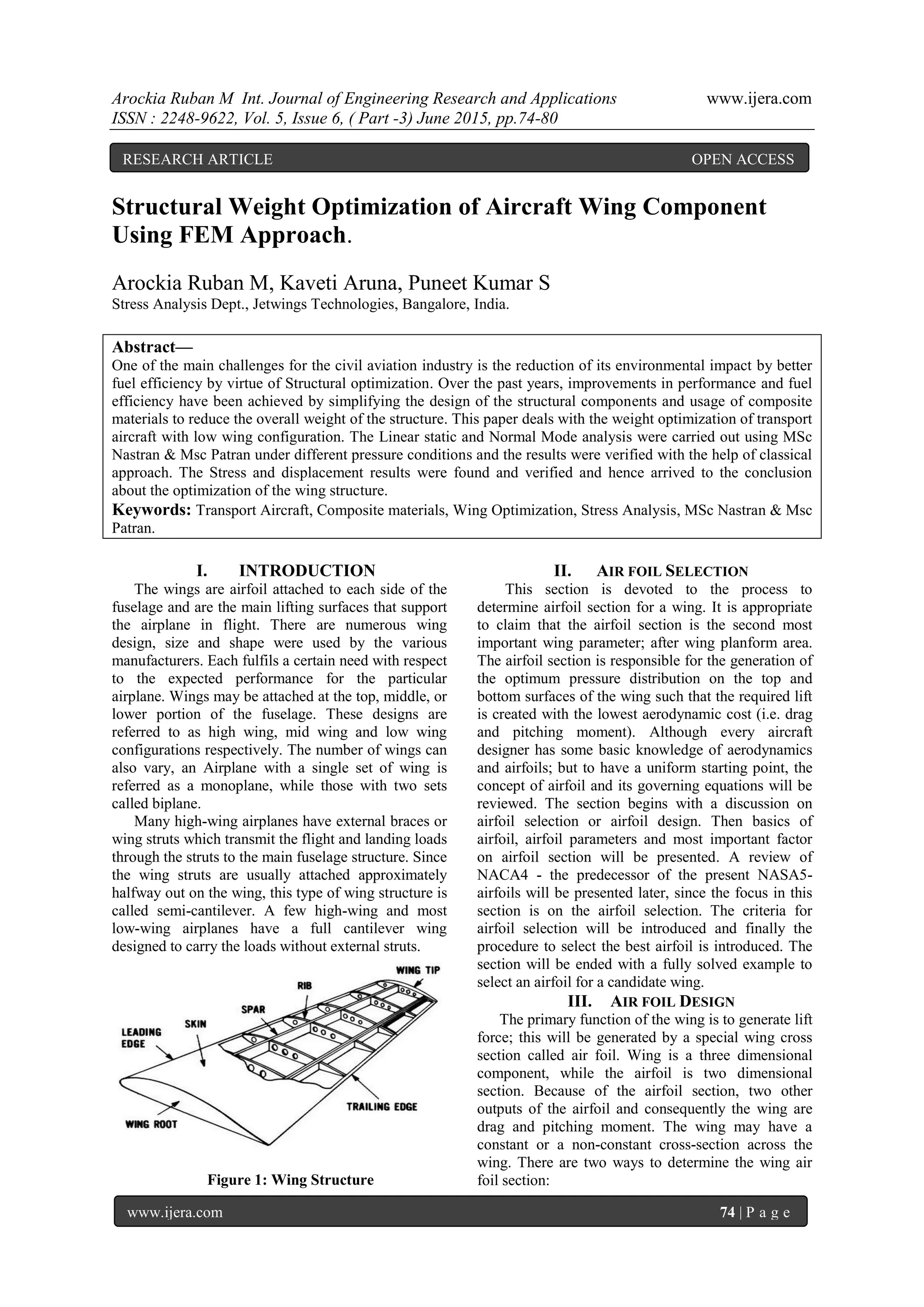
Table 2: Mechanical Property Carbon Fibre
Reinforced Plastics (Cfrp).
Sl.No
Mechanical
Properties
Value Unit
1
Young’s
Modulus,E11
138.6 GPa
2
Young’s
Modulus,E22
82.7 GPa
3
Poisson’s
Ratio
0.25 -
4
Ultimate
Strength
1450 MPa
5
Shear
modulus, 12
4120 MPa
6
Shear
modulus, 23
0.6 MPa
7
Shear
modulus, 13
0.6 MPa
8
Yield
Strength
600 Mpa
9 Density
1.76E-
6
Kg/mm3
10
Specific
Gravity
1.6 -
Sl.
NO
Properties value units
1 Density 2.78E-6 [kg/mm3]
2
Young’s
Modulus,
73.1 [GPa]
3
Shear
Modulus,
28 [GPa]
4
Poison’s
ratio
0.33
5
Ultimate
strength
483 [MPa]
6
Yield
strength
385 [MPa]
7
Shear
strength 283 [MPa]
4. Arockia Ruban M Int. Journal of Engineering Research and Applications www.ijera.com
ISSN : 2248-9622, Vol. 5, Issue 6, ( Part -3) June 2015, pp.74-80
www.ijera.com 77 | P a g e
VII. FINITE ELEMENT MODELLING OF
WING COMPONENT
About FEA and Applications
THE finite element method is a numerical method
that can be used for the accurate solution of complex
engineering problems. The method was first
developed in 1956 for the analysis of aircraft
structural problems. Thereafter, within a decade, the
potentialities of the method for the solution of
different types of applied science and engineering
problems were recognized. Over the years, the finite
element technique has been so well established that
today it is considered to be one of the best methods
for solving a wide variety of practical problems
efficiently. In fact, the method has become one of the
active research areas for applied mathematicians. One
of the main reasons for the popularity of the method
in different fields of engineering is that once a general
computer program is written, it can be used for the
solution of any problem simply by changing the input
data. A variety of specializations under the umbrella
of the mechanical engineering discipline (such as
aeronautical, biomechanical, and automotive
industries) commonly use integrated FEM in design
and development of their products. Several modern
FEM packages include specific components such as
thermal, electromagnetic, fluid, and structural
working environments. In a structural simulation,
FEM helps tremendously in producing stiffness and
strength visualizations and also in minimizing weight,
materials, and costs.FEM allows detailed visualization
of where structures bend or twist, and indicates the
distribution of stresses and displacements. FEM
software provides a wide range of simulation options
for controlling the complexity of both modeling and
analysis of a system. Similarly, the desired level of
accuracy required and associated computational time
requirements can be managed simultaneously to
address most engineering applications. FEM allows
entire designs to be constructed, refined, and
optimized before the design is manufactured. This
powerful design tool has significantly improved both
the standard of engineering designs and the
methodology of the design process in many industrial
applications. The introduction of FEM has
substantially decreased the time to take products from
concept to the production line. It is primarily through
improved initial prototype designs using FEM that
testing and development have been accelerated. In
summary, benefits of FEM include increased
accuracy, enhanced design and better insight into
critical design parameters, virtual prototyping, fewer
hardware prototypes, a faster and less expensive
design cycle, increased productivity, and increased
revenue. FEA has also been proposed to use in
stochastic modeling for numerically solving
probability models
VIII. PROCEDURE INVOLVED IN STRESS
ANALYSIS
General procedure of FEM
i. Importing model or creating the model
ii. Discretization of the structure
iii. Applying material
iv. Applying load and boundary conditions
v. Analysis
vi. Solver
vii. Result
IX. STATIC ANALYSIS OF SWEPT
BACK WING
Discretization of the Structure
The next step in the finite element method is to
divide the structure region into subdivisions or
elements. Hence, the structure is to be modeled with
suitable finite elements. The number, type, size, and
arrangement of the elements are to be decided. For
Wing meshing is done by 1D and 2D elements.1D
elements are used in spar flange section. Spar web is
meshed manually using quad elements. Wing skin is
meshed automatically by using Quad4 elements. Ribs
are meshed by manually using quad and tri
elements.1D elements are applied to the after
meshing, equivalence is applied to delete duplicate
node. Next is verification of mesh elements. First
verified for element boundaries, duplicate elements,
normals and geometry fit meshing Quad element is
checked for error. Errors in quad element are
• Aspect ratio
• Warp
• Taper
• Skew
Table: 5 Type of Elements Used
Sl.
no
Component
Element
Type
Number of
elements
1 Spar Flange Bar 360
2 Skin
Quad &
Tria
5768
3 Spar Web Quad 180
4 Ribs
Quad &
Tria
348
5. Arockia Ruban M Int. Journal of Engineering Research and Applications www.ijera.com
ISSN : 2248-9622, Vol. 5, Issue 6, ( Part -3) June 2015, pp.74-80
www.ijera.com 78 | P a g e
Figure 3: Finite Element Model
X. Properties
Sl.
no
Component
Element
Type
properties
1
Spar
Flange
Bar
Width=40 mm
Height=12mm
Material:
Aluminum 2024
T3
2 Skin
Quad &
Tria
Thickness=2mm
Material:
Aluminum 2024
T3
3 Spar Web Quad
Thickness=15mm
Material:
Aluminum 2024
T3
4 Ribs
Quad &
Tria
Thickness=3mm
Material:
Aluminum 2024
T3
XI. Load calculation:
Limit Load = Take of weight x Lift
Lift Load = 4
Design load = Limit Load x Factor of Safety
Factor of Safety= 1.5
Load on semi span = Design load /2
Exposed wing area = (b/2)*(Croot+Ctip)
Pressure Load on wing = Load on semi span /
wing area
XII. Analysis of Swept Back Wing Model
The Analysis results shown in below figures and
the material wise results are tabulated. The validation
of wing structure is done by Reserve Factor. The
static analysis results are done by failure theories for
both metallic and composite material.
XIII. Results of Aluminum 2024 T3
Figure 4: Max. Principal Stress = 202 N/mm2
Figure 5: Von Mises Stress = 210 N/mm2
Figure 6: Max. Shear Stress = 112 N/mm2
6. Arockia Ruban M Int. Journal of Engineering Research and Applications www.ijera.com
ISSN : 2248-9622, Vol. 5, Issue 6, ( Part -3) June 2015, pp.74-80
www.ijera.com 79 | P a g e
Figure 7: Max. Displacement = 186 mm
XIV. Results of CFRP
Figure 8: Max. Principal Stress = 217 N/mm2
Figure 9: Von Mises Stress = 250 N/mm2
Figure 10: Max. Shear Stress = 136 N/mm2
Figure 11: Max. Displacement = 97.9 mm
XIV. Failure Indices
Figure 12: Failure Indices for CFRP = 0.19
Table: 7 Reserve Factor Table for aluminum
2024 T3
Sl.No
Type Of
Stress
Allowable
Stress
Obtained
Stress
R.F
1
Max.
Principal
385 202 1.90
2
Von
Mises
385 210 1.83
3
Max.
Shear
231 112 2.05
7. Arockia Ruban M Int. Journal of Engineering Research and Applications www.ijera.com
ISSN : 2248-9622, Vol. 5, Issue 6, ( Part -3) June 2015, pp.74-80
www.ijera.com 80 | P a g e
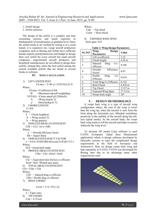
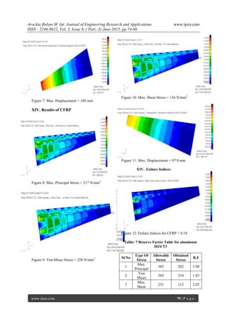
Table: 8 Reserve Factor Table for CFRP
Sl.No
Type Of
Stress
Allowable
Stress
Obtained
Stress
R.F
1
Max.
Principal
600 217 2.7
2
Von
Mises
600 250 2.4
3
Max.
Shear
360 136 2.6
XV. Normal Mode Analysis:
For Aluminum 2024 T3
Sl.
NO
Mode Eigen Value
Frequency
(Hz)
1 1st
Bending 2.64 1.62
2 1st
Twisting 14.7 3.84
3 2nd
Bending 15.4 3.92
4 1st
Axial 20.6 4.54
5 2nd
Axial 21.4 4.63
6 2nd
Twisting 23.3 4.82
For CFRP
Sl.
NO
Mode Eigen Value
Frequency
(Hz)
1 1st
Bending 3.35 1.83
2 1st
Twisting 12.0 3.47
3 2nd
Bending 13.7 3.71
4 1st
Axial 16.6 4.08
5 2nd
Axial 18.0 4.24
6 2nd
Twisting 19.9 4.46
XVI. Structural Weight Optimization:
From the above analysis we have proved that the
CFRP material is having high Strength to weight
ratio. The initial Aluminum 2024 T3 material mass
is 238.6 Kg.
Further modification of CFRP material is having
mass of 117.9 Kg which is having 50.58% less
weight than the initial mass.
XVII. Conclusion:
The wing structure with internal components
is designed and FE modeling is carried out for the
above mentioned loads and Boundary conditions.
The results for the Static Analysis is obtained and
plotted and Reserve factor values are calculated.
The reserve factors for all the structural
components are studied and scrutinized, the model
is structurally good and can withstand the loads
acting on it. It was also proved that the composite
material is having high strength and is structurally
stable for the loads applied. The structural
behavior of various composite materials was also
understood and obtained good knowledge on the
practical stress analysis of composite structures
using FEA process.
Reference:
[1] Michael Chun-Yung Niu – “Airframe
Structural Design”.
[2] Igor Kokcharov – “Structural Integrity
Analysis”.
[3] “Introduction to Composite Materials”,
David Roylance March 24, 2000.
[4] “Overview on Drag Reduction Technologies
for Civil Transport Aircraft”, J. Reneaux, 28
July 2004.
[5] Stress Analysis and Weight Optimization of
a Wing Box Structure Subjected to Flight
Loads.
[6] Design and Stress Analysis of a General
Aviation Aircraft Wing.