ATDA Commercial Transport Airframe Part 2.pdf
•
0 likes•199 views

This document provides an overview of Mr. Geoffrey Allen Wardle's airframe design study from 2012-2020 for the ATDA aircraft. It discusses the selection of the wing planform and aerofoil geometry for the ATDA, including parameters like aspect ratio, sweep angle, taper ratio, and thickness-to-chord ratio. It also outlines the process used to determine values for the mean aerodynamic chord length, wing area, root and tip chords, aerodynamic center, and center of gravity.

Recommended
Recommended
More Related Content
What's hot
What's hot (20)
Similar to ATDA Commercial Transport Airframe Part 2.pdf
Similar to ATDA Commercial Transport Airframe Part 2.pdf (20)
More from Geoffrey Wardle. MSc. MSc. Snr.MAIAA
More from Geoffrey Wardle. MSc. MSc. Snr.MAIAA (7)
Recently uploaded
Recently uploaded (20)
ATDA Commercial Transport Airframe Part 2.pdf
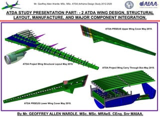
- 1. Mr. Geoffrey Allen Wardle. MSc. MSc. ATDA Airframe Design Study 2012-2020 ATDA STUDY PRESENTATION PART: - 2 ATDA WING DESIGN, STRUCTURAL LAYOUT, MANUFACTURE, AND MAJOR COMPONENT INTEGRATION. By Mr. GEOFFREY ALLEN WARDLE. MSc. MSc. MRAeS. CEng. Snr MAIAA. ATDA PRSEUS Lower Wing Cover May 2019. ATDA Project Wing Structural Layout May 2019. ATDA Project Wing Carry Through Box May 2019. ATDA PRSEUS Upper Wing Cover May 2019.
- 2. Mr. Geoffrey Allen Wardle. MSc. MSc. ATDA Airframe Design Study 2012-2020 This presentation has been created, for the sole purpose of private study and is not the work of a company or government organisation it entirely the work of the author using resources in the public domain. The final paper will be submitted for peer - review to the American Institute of Aeronautics and Astronautics, Design Engineering Technical Committee, and the RAeS Structures and Materials Group, for pre submission assessment. Readers must be aware that the work contained may not be necessarily 100% correct, and caution should be exercised if this project or the data it contains is being used for future work. If in doubt, please refer to the AIAA, Design Engineering Technical Committee and the author. All of the views and material contained within this document are the sole research of the author and are not meant to directly imply the intentions of the Boeing Company, Airbus Group, GKN Aerospace, or any contractor thereof, or any third party at this date. Although the USAF and NASA have awarded contracts for studies into stitched composite transport aircraft structures, this work is not the product of their results or any part of their body of research, and should not be considered as such. This document contains no material what so ever generated or conceived by myself or others during my employment with BAE SYSTEMS (PLC), or that is governed by ITAR restrictions. This work is solely my own creation and is based on my own academic studies and literature research and the distribution of all information contained within this document is unlimited public release and has been approved through the AIAA. This document and any part thereof cannot be reproduced by any means in any format or used for any other research project without consultation with AIAA Design Engineering Technical Committee or the author. 2 Presentation “Health” Warning. .
- 3. Mr. Geoffrey Allen Wardle. MSc. MSc. ATDA Airframe Design Study 2012-2020 3 This is an overview covering my current private design trade studies into the incorporation of new structural technologies and manufacturing processes into a future transport airframe design, and the incorporation of mission adaptive wing (MAW) technology for per review through the AIAA This study has been undertaken after my 13 years at BAE SYSTEMS MA&I, in airframe design development as a Senior Design Engineer, and my Cranfield University MSc in Aircraft Engineering completed in 2007(part-time), and was commenced in 2012 and I aim to complete it at the end of 2020. This utilises knowledge and skills bases developed throughout my career in aerospace, academic studies and new research material I have studied, to produce a report and paper exploring the limits to which an airframe research project can be perused using a virtual tool set, and how the results can be presented for future research and manufacturing. The toolsets used are Catia V5.R20 for design / analysis / kinematics / manufacturing simulation: PATRAN / NASTRAN for analysis of composite structures: AeroDYNAMIC™ for analysis of aircraft OML / Structural Loads / performance. This work will also form the basis for a PhD study, it is the product of my own research, and has not in any part been produced or conceptualised during my employment with BAE SYSTEMS or any company which is any part thereof. About this presentation:- This presentation is Part 2 of a series of 5 presentation Parts which cover the airframe major structural component development and engine and landing gear integration, and assembly manufacturing technologies. The contents of this presentation are given in the following slide. Overview of my current research activities in aircraft design for the ATDA paper.
- 4. Mr. Geoffrey Allen Wardle. MSc. MSc. ATDA Airframe Design Study 2012-2020 Section 1:- Wing planform and aerofoil selection aerodynamics of the ATDA wing. Section 2:- Roll, manufacturing methods, and layout of large aircraft wing structural members: Section 3:- Flight control surfaces sizing and design: Section 4:- The design and structural layout of the ATDA wing box: Section 5:- Wing fuel tank and engine / pylon integration into the ATDA wing: Section 6:- Main Landing Gear Integration in wing torsion box and wing carry through box (in work): Section 7:- The design, structural layout and sizing of the ATDA wing torsion and carry through box (in work): Section 8:- Wing flight control system and high lift device mechanical integration (in work): Section 9:- Wing assembly automation of the wing torsion and carry trough box (in work). THIS WORK MAY NOT BE REPRODUCED WITHOUT EXPRESS PERMISSION OF MYSELF, RAeS, AND AIAA. 4 Table of contents of this ATDA Study Presentation Part 2.
- 5. Mr. Geoffrey Allen Wardle. MSc. MSc. ATDA Airframe Design Study 2012-2020 As stated in Part 1 the fundamental reasons for this research is to reduce the structural weight of the airframe and make it easer to produce through PRSEUS technology. The former is intended to reduce the amount of CO2 emitted from kerosene – burning aircraft engines which is solely dependent on the amount of fuel consumed (discussed below), and the latter will reduce costs both of acquisition and ownership through life maintenance (discussed in Part 1). Figure 1 gives the overall dimensions of the ATDA, and Table 1 gives the configuration desired performance and baseline dimensions for the ATDA. The variables influencing fuel consumption can easily be examined using the Breguet range equation. One form of the range equation for the special case of constant lift coefficient – i.e. at constant cruise / climb – reads:- WF = WTO * 1 – exp R equation (1.0) X With WTO representing aircraft take - off weight, R the mission range; X = L / D * V = L/D *ᶇ * H equation (1.1) TSFC *g g V = the cruise speed; TSFC = the thrust specific fuel consumption; ᶇ = the overall engine efficiency; H = the cabrific value of the fuel. 5 Section 1:- Wing planform and aerofoil selection aerodynamics of the ATDA wing.
- 6. Mr. Geoffrey Allen Wardle. MSc. MSc. ATDA Airframe Design Study 2012-2020 Now equation 1.0 can be rewritten to give fuel consumption in kg per kg payload as:- WF 1 + WE * exp R*g πeb² -1 equation (1.3) Wp Wp CL ᶇth ᶇprop H Where:- CDo = the zero-lift drag; S = the wing area; e = the Oswald factor; B = the wing span; CL = the aircrafts lift coefficient; ᶇth = the engines thermal efficiency; ᶇprop = the engines propulsive efficiency. Minimising fuel weight, with respect to CO2 emission for a given payload and range can be obtained by:- Aerodynamics:- Maximise CL, e, and b: Minimise CDo and S; Structure:- Minimise WE / Wp ( Weight empty / Weight payload); Engine:- Maximise ᶇth and ᶇprop ; Fuel:- Maximise H This work is to modify the structural weight parameters, improve aerodynamics an efficiency. 6 My requirements research breakdown for the ATDA aircraft design project. = S C²L CDo +
- 7. Mr. Geoffrey Allen Wardle. MSc. MSc. ATDA Airframe Design Study 2012-2020 Figure 1:- Overall configuration and dimensions of the ATDA baseline aircraft. 7 70.52m (231ft 3.3in) Code F 18.34m (60ft 7in) 11.51m (37ft 1.6in) 30.58m (100ft 3.8in) O/A 75.87m (248ft 1.3in) Code E 74.47m (244ft 3.8in) 34.45m (113ft 2.4in) O/A 75.27m (246ft 10.7in) Fuselage sized for twin aisle 9 abreast 2 LD-3 containers 5.99m (235.85in) Section on „A‟ „A‟ „A‟ 17.85m (58ft 4.6in) 11.92m (39.136ft) 7.771m 14.154m 17.248m
- 8. Mr. Geoffrey Allen Wardle. MSc. MSc. ATDA Airframe Design Study 2012-2020 IMPERIAL DATA. METRIC DATA. Wing Span (ft / in) 231 / 3.3 Wing Span (m) 70.52 Length (ft / in) 240/88 Length (m) 75.88 Wing Area (sq ft) 4,375.49 Wing Area (sq m) 406.481 Fuselage diameter (in) 235.83 Fuselage diameter (m) 5.99 Wing sweep angle 35° Wing sweep angle 35° Fuselage Length (ft /in) 244 / 3.8 Fuselage Length 74.47 Engine number / type 2 X RR Trent XWB Engine number / type 2 X RR Trent XWB T-O thrust (lb) 83,000 T-O thrust (kN) 369.0 Max weight (lb) 590,829 Max weight (tonnes) 268.9 Max Landing (lb) 451,940 Max Landing (tonnes) 205.0 Max speed (mph) 391 Max speed (km/h) 630 Mach No 0.89 Mach No 0.89 Range at OWE (miles) 9,631 Range at OWE (km) 15,500 Cruise Altitude (ft) 45,000 Cruise Altitude (m) 13,716 8 Table 1: - Initial Configuration Aircraft Data for the baseline ATDA study.
- 9. Mr. Geoffrey Allen Wardle. MSc. MSc. ATDA Airframe Design Study 2012-2020 Starting with the wing, the major drivers in the baseline wing structural design considered in this study are: - Sweep angle: Front and rear spar locations: Main undercarriage location to be aft of the Centre of Gravity (C of G) and its sizing, weight, and actuation system: Engine pylon installation and mounting: Flying control surface actuator and mounting positions: Fuel tank boundaries and system couplings employed and systems installation to ensure there is no trapped fuel within the wing structure: The rib layout to support load transfer and structural stability of the wing box: Materials selection and manufacturing and assembly methods stitching and bolting for CFC wing structures, and the reference ATDA is shown in figure 2. The major parameters of wing definition as follows: - Size: Aspect Ratio: Sweep angle: Taper Ratio: Wing Loading and Thickness, which are derived from: - (1) LE = wing leading edge sweep angle: (2) A = wing planform area: (3) Ĉ = Mean Aerodynamic Chord: (4) Cr = Root Chord: (5) Ct = Tip Chord: (6) t / c = Thickness chord ratio: (7) b = Span = 2 x s (where s = semi-span): (8) S = wing area: (9) yMAC = the y station of the Mean Aerodynamic Chord (10) Xac = aerodynamic centre of pressure in the x axis mapped on the MAC. For the baseline wing: - the Aspect Ratio from b² / S = 10.15: the MAC Ĉ length = 5.89m (259”) and yMAC = 15.14m (596”) (from graphical evaluation number 1 in figure 2): LE = 35º: A = 406.481m² (4,375ft²): Cr = 13.97m (550”): Ct = 3.81m (150”): t / c = 0.27: b = 64.76m (2,549.5”): and S = 413.02m² (640,199 inch²): the Centre of Gravity (number 2 in figure 57) was determined as 35% root chord this allows for fuselage length growth (as per reference 4) = 4.89m (192.5”): taper ratio λ = Ct / Cr = 0.27. The initial estimated wing loading is 10,309kN/m² (124.6lbs/ft²) within 82.7kN/m² (1lb/ft²) of published figures for the Airbus A350: Xac = 12.07m (475”). See figure 57 for MAC, aerodynamic centre of pressure, and C of G mapping on the reference wing. 9 The ATDA wing planform selection and aerofoil geometry.
- 10. Mr. Geoffrey Allen Wardle. MSc. MSc. ATDA Airframe Design Study 2012-2020 10 Figure 2:- ATDA baseline reference wing graphical determination of MAC. 1 Croot 13.97m (550”) Croot 13.97m (550”) Ctip 3.81m (150”) Ctip 3.81m (150”) b/2 32.37m (1274.5”) MAC (Ĉ) length 5.89m (232”) 50% Chord reference wing. 100% Chord reference wing 7.69m (303”). 2 Diagonal Construction Line. Aircraft Centre Line CL. yMAC (Ĉ) 15.14m (596”) Aerodynamic centre of a subsonic swept wing is approximately located at Xac = yMAC tan LE+ 0.25MAC the value = 12.07m (475”) in X from reference wing tip. 3 3 Engine Pylon Centre Line. 35º
- 11. Mr. Geoffrey Allen Wardle. MSc. MSc. ATDA Airframe Design Study 2012-2020 The important parameters in long range transport aircraft wing design are:- The Aspect Ratio (b²/S): - Increased Aspect Ratio gives improved Lift and Drag and a greater Lift curve slope, and for subsonic transports AR values between 8-10 are considered typical. For initial design purposes an Aspect Ratio from historical data can be used, but trade studies using MDO toolsets are needed for definitive values. Selecting a higher value AR has beneficial effects at high altitude cruise to give greater range and endurance, and when usable take-off incidence is restricted by ground clearance, however this is not the case for tactical military aircraft in low altitude high-speed flight where profile drag is the dominant factor. Historically the Aspect Ratio has been used as a primary indicator of wing efficiency based on the square of the wing span divided by the wing reference area. In fact the AR could be used to estimate subsonic Lift / Drag where Lift and Drag are most directly affected by the wing span and wetted area but for one major problem i.e. drag at subsonic speeds is composed of two parts:- “Induced“ drag caused by the generation of lift and therefore primarily a function of the wing span: and “Zero-lift” or “Parasitic” drag which is not related to lift but is primarily skin-friction drag, and as such is directly proportional to the total surface area of the aircraft exposed (“wetted”) to the air. Therefore the ratio of the wetted area of the full aircraft to the reference wing area ( Swet / Sref ) can be used along with the aspect ratio as a more reliable early estimate of L/D, as the wetted-area ratio is clearly dependent on the actual configuration layout. This suggests a new parameter “Wetted Aspect Ratio” which is defined as the wingspan squared divided by the total aircraft wetted area. This is very similar to the aspect ratio except that it considers total wetted area instead of the wing reference area. AeroDYNAMIC™ MDO toolset enables this to be done within its design module and compared against the Catia V5 model. 11 The ATDA wing planform selection and aerofoil geometry (continued).
- 12. Mr. Geoffrey Allen Wardle. MSc. MSc. ATDA Airframe Design Study 2012-2020 The leading edge sweep angle LE: - The greater the sweep angle the higher the lift dependent drag and requires increased roll control for cross wind take-offs. However, it delays drag rise „M‟ and reduces the lift curve slope. For commercial transports the leading edge sweep angle ranges between 28º to 35º with the A350 being at the top of this range and this was adopted for the ATDA study wing as a result of AeroDYNAMIC analysis for high altitude cruise at Mach 0.89 at 39,000ft (11,887.2m). Taper ratio Ct / Cr: - Taper transfers load from the tip towards the root, thus increasing the likelihood of tip stall (which gives wing droop and pitch up on a swept wing). For swept wing increased taper gives lower trailing edge sweep, which enhances the effectiveness of trailing edge flaps and controls (giving reduced take-off and landing speeds and improving controllability in cross winds), the taper ratio selected for the baseline wing was 0.27 based on AeroDYNAMIC analysis. Thickness: - Thick section wings incur a Profile Drag Penalty. Increasing thickness dose however, give increased maximum lift, eases mechanisation of flaps and slats, generates a lighter structure and presents a greater internal volume for fuel carriage. Camber: - Camber is added to enhance lift. It is however detrimental at low speeds. High Lift Devices: - There are of primary benefit on thin swept wings at supersonic speeds, although high lift leading edge slats are used by most subsonic transports, and are incorporated into the baseline wing design as described below. Winglets:- Described below which reduce induced drag. Aerofoil: - Section selection see figures 3 through 6 this has a major effect on drag. 12 The ATDA wing planform selection and aerofoil geometry (continued).
- 13. Mr. Geoffrey Allen Wardle. MSc. MSc. ATDA Airframe Design Study 2012-2020 13 Figure 3:- Typical Breakdown of aircraft drag by form and component. Total Drag Parasitic Wave / Interference Lift Dependant Drag Friction Drag Friction Drag Pylons and Fairings Nacelles Horizontal Tail Vertical Tail Wing Fuselage From this it can be seen that the largest contributions to Friction drag are the wings and fuselage. In this study the ATDA attempts to reduce both:-for the wing by selection of supercritical aerofoil selection below: and for the fuselage by applying aerodynamic tailored shaping for the nose and the rear sections see the Part 3 presentation.
- 14. Mr. Geoffrey Allen Wardle. MSc. MSc. ATDA Airframe Design Study 2012-2020 14 Figure 4:- Aerofoil profile selection based on Friction Drag Reduction. Figure 4a/b:- Flow fields around 4(a) conventional aerofoil 4(b) supercritical aerofoil. Figure 5(a) Figure 5(b) Figure 4(c):- Sketches of root NASA SC(2) 0414 and tip NASA SC(2) 0410 aerofoil profiles.
- 15. Mr. Geoffrey Allen Wardle. MSc. MSc. ATDA Airframe Design Study 2012-2020 15 Figure 5:- Aerofoil supercritical profile selection to reduce wing friction drag. LAMINA TURBULENT Moment reference centre. 0.25 0.50 0.75 1.00 Reference line. NASA SC (2) 0410 Aerofoil. 0.1 - 0.1 V= freestream Laminar Boundary Layer V= freestream Turbulent Boundary Layer NB: - The Laminar boundary layer has much lower friction drag.
- 16. Mr. Geoffrey Allen Wardle. MSc. MSc. ATDA Airframe Design Study 2012-2020 16 Figure 6:- Drag Coefficient (Skin Friction Drag). 0.005 0.0 10.0 Mio 20.0 Mio 0.001 0.002 0.003 0.004 C l Reynolds Number Turbulent 50% Laminar Laminar NB: -A substantial drag reduction is possible, even if only part of surface is Laminar.
- 17. Mr. Geoffrey Allen Wardle. MSc. MSc. ATDA Airframe Design Study 2012-2020 17 The structural layout of the reference wing, and evolved wing based on the following fundamentals, the wing has structurally to be both a span-wise and chord-wise beam and posses adequate torsional stiffness and therefore be able to react the loads outlined in figure 7. Figure 8 illustrates the control surfaces on the wing of the ATDA subsonic composite concept airliner, and shows how the numerous leading and trailing edge devices occupy a significant portion of the chord. The consequence of this is that only approximately half of the chord is available for the span-wise beam of the torsion box, however it is the deepest portion and this is preferable for both bending and torsion. The primary load direction is well defined and is span-wise and therefore wings are good candidates for the application of carbon – fibre composites providing the overall size is such that it can be built with the minimum number of joints. The primary wing box components of the baseline wing as is common with large transport aircraft are:- the wing skin covers which form the lifting surface and transmit wing bending and torsion loads, and these are stabilized with span-wise stringers to inhibit cover skin buckling, the stringers reduce cover skin thickness requirements and hence cover weight as outlined below, (either CFC or metallics are used for cover skins e.g. A380 uses 7449 and 7055 Al upper skins and 2024 and 2026 Al lower skins): the front and rear spars which in conjunction with the stringer stiffened skin transmit bending and torsion loads, and consist of a web to react vertical shear loads, and edge flanges to react the wing bending loads (and can be CFC or metallic e.g. A380 uses 7085 and 7040 Al for spars: and ribs which maintain the aerodynamic shape of the wing cross-section, and structurally transmit local loads chord-wise across to the span-wise torsion box, the ribs stabilize the spars and skins in span-wise bending. In this study CFC cover skins / spars / and some ribs is the baseline. Section 2:- Roll and layout of large aircraft wing structural members.
- 18. Mr. Geoffrey Allen Wardle. MSc. MSc. ATDA Airframe Design Study 2012-2020 Figure 7:- ATDA Wing complexity as a complete structural component. Aircraft Sizing Determined by Wing Architecture (e.g. Tail sizing: Landing gear geometry: Belly Fairing: etc. Complex systems installation (Fuel: Pneumatics: Electrical and FTI provision) Aircraft Configuration influenced by wing definition (e.g. C of G: Ground Line: Cargo hold position: PAX evacuation: etc.). Determines Aircraft High and Low speed performance. Complex assembly and equipping. Critical Structures and Systems Integration (Root Joint: Landing Gear: Pylon: and Moveable's). Optimising aerodynamics / structural geometry (Twist: Taper: Camber: Sweep: and Gulling: etc.). Particular Risk Mitigation (Bird Strike: WTF: Lightening Strike: UERF). Managing High Load Inputs (Pylon: Landing Gear: Flaps Integration). Optimise design and manufacture of thick and complex structures (e.g. FTE: Bottom Cover Skin: etc.). Combined Loading effects (Ground: Manoeuvre: Gust: and Flight loads). 18
- 19. Mr. Geoffrey Allen Wardle. MSc. MSc. ATDA Airframe Design Study 2012-2020 19 Figure 8:- High lift devices and control surface layout of the ATDA concept airliner. Six Outboard Leading edge slats. Droop nose Leading edge slat. Two Inboard Spoilers with droop function. Five Inboard Spoilers with droop function. Outboard Flap single pivot. Inboard Flap single pivot. All Speed Aileron. Low Speed Aileron. Rudder. (Planform area 15m²) Port Elevator (Planform area 10 .18m²) Stbd Elevator. (Planform area 10.18m²)
- 20. Mr. Geoffrey Allen Wardle. MSc. MSc. ATDA Airframe Design Study 2012-2020 20 COVER SKINS: - The covers form the lifting surface of the wing box and are subjected to span- wise bending flight loads, the upper wing cover is subjected to primary compression loads, and lower wing cover is subjected to primary tension loads. The upper wing covers are also subjected to aerodynamic suction and fuel tank pressures, and both covers are subjected to chord-wise shear due to the aerodynamic moment on the wing torsion box. Composite wing cover skins shown in figure 9(a)(b)(c) can be aeroelastically tailored using: - 0º plies to react span-wise bending: 45º and -45º plies to react chord-wise shear: and 90º plies to react aerodynamic suction and internal fuel tank pressures, theses cover skins are monolithic structures and not cored. Combined with co- bonded stringers, this produces much stronger yet lighter covers which are not susceptible to corrosion and fatigue like metallic skins. The production method of these cover skins is by Fiber Placement:- which is a hybrid of filament winding and automated tape laying, the machine configuration is similar to filament winding and the material form is similar to tape laying, this computer controlled process uses a prepreg Tow or Slit material form to layup non-geodesic shapes e.g. convex and concave surfaces, and enables in-place compaction of laminate, however maximum cut angle and minimum tape width and minimum tape length impact on design process. The wing cover skin weight in large transports, can be reduced by applying different ply transition solutions to the drop off zones as shown in figure 10(a) through (d), maintaining the design standard 1:20 ramps in the direction of principal stress (span-wise), and using 1:10 ramps in the transverse (chord-wise) direction, as shown for the ATDA wing covers, this requires stress approval based on analysis. Because the wing chord depth of the transport aircraft considered exceeds 11.8” to reduce monolithic cover skin weight and inhibit buckling co-bonded CFRP stiffeners are used as detailed below and shown in figures 11, 12, and 13 for the baseline ATDA reference structure. Roll and layout of large aircraft wing structural members ( CFC cover skins).
- 21. Mr. Geoffrey Allen Wardle. MSc. MSc. ATDA Airframe Design Study 2012-2020 Figure 9(a):- Fibre Orientation Requirements for CFC Wing Skins / covers. Tension Bottom Wing Cover Skin. Compression Top Wing Cover Skin. 0º Plies are to react the wings spanwise bending. The 4 Primary Ply Orientations Used for Wing Skin Structural Plies. 21
- 22. Mr. Geoffrey Allen Wardle. MSc. MSc. ATDA Airframe Design Study 2012-2020 Figure 9(b):- Fibre Orientation Requirements for CFC Wing Skins / covers. 22 Centre Of Pressure Engine / Store Loading Flexural Centre The 90º plies react the internal fuel tank pressure and aerodynamic suction loads. The 45º and 135º Plies in the Wing Cover Skins react the chordwise shear loads. Pressure Loading Aerodynamic suction Loading
- 23. Mr. Geoffrey Allen Wardle. MSc. MSc. ATDA Airframe Design Study 2012-2020 23 Figure 9(c):- ATDA Design Load Cases for PRSEUS Lower Wing Skins / Covers. VERTICAL GUST (CLEAN WING) VERTICAL GUST JACKING VERTICAL GUST* *ENVELOPE OR QUISI-FLEXIBLE WING GUST ALTITUDE WEIGHTED TUNED GUST STR1 STR2 STR3 STR4 STR5 STR6 STR7 STR8 STR9 Note:- Rib 0 C = Closure Rib: STR1 = Stringer One (etc.) This is the PRSEUS ATDA Skin layout.
- 24. Mr. Geoffrey Allen Wardle. MSc. MSc. ATDA Airframe Design Study 2012-2020 Fig 10(a):- ATDA Structural Ply Thickness Zones Upper Wing Cover Skin Baseline 24 PLY LEGEND. This Legend gives the thickness of plies in each orientation. “t” 0º 90º 45º 135º FWD IN BD 24.0 6.0 3.0 7.5 7.5 24 mm 20.0 4.0 3.0 6.5 6.5 16.0 4.0 3.0 4.5 4.5 16 mm 12.0 3.0 2.0 3.5 3.5 12 mm 10.0 3.0 2.0 2.5 2.5 10 mm 8.0 3.0 1.0 2.0 2.0 8 mm 6.0 2.0 1.0 1.5 1.5 6 mm 20 mm PLY DROP OFFS: - 1:20 SPANWISE / 1:10 CHORDWISE. (For ATDA study un-symmetrical ply drop off e.g. 1:20 in direction of principal stress and 1:10 in the transverse direction for weight reduction). Outer OML Skin Ply. See also figure 28 for lightening strike protection and figures 29 and 30 for BVID protection. 6.0 2.0 1.0 1.5 1.5 6 mm
- 25. Mr. Geoffrey Allen Wardle. MSc. MSc. ATDA Airframe Design Study 2012-2020 Fig 10(b):- ATDA Structural Ply Thickness Zones Upper Wing Cover Skin PRSUES. 25 PLY LEGEND. This Legend gives the thickness of plies in each orientation. “t” 0º 90º 45º 135º FWD IN BD 18.0 4.0 2.0 6.0 6.0 18 mm 16.0 2.0 2.0 6.0 6.0 14.0 3.0 3.0 4.0 4.0 14 mm 12.0 3.0 2.0 3.5 3.5 12 mm 10.0 3.0 2.0 2.5 2.5 10 mm 8.0 3.0 1.0 2.0 2.0 8 mm 6.0 2.0 1.0 1.5 1.5 6 mm 16 mm PLY DROP OFFS: - 1:20 SPANWISE / 1:10 CHORDWISE. (For ATDA study un-symmetrical ply drop off e.g. 1:20 in direction of principal stress and 1:10 in the transverse direction for weight reduction). Outer OML Skin Ply. See also figure 28 for lightening strike protection and figures 29 and 30 for BVID protection. NB:- These are first pass results and are conservative. 6.0 2.0 1.0 1.5 1.5 6 mm
- 26. Mr. Geoffrey Allen Wardle. MSc. MSc. ATDA Airframe Design Study 2012-2020 Fig 10(c):- ATDA Structural Ply Thickness Zones Lower Wing Cover Skin Baseline 26 PLY DROP OFFS: - 1:20 SPANWISE / 1:10 CHORDWISE. (For ATDA study un-symmetrical ply drop off e.g. 1:20 in direction of principal stress and 1:10 in the transverse direction for weight reduction). 15 mm 10 mm 10 mm 20 mm 20 mm 15 mm 10 mm 6 mm 6 mm 8 mm 6 mm 6.0 2.0 1.0 1.5 1.5 6.0 2.0 1.0 1.5 1.5 “t” 0º 90º 45º 135º PLY LEGEND. 8.0 4.0 1.0 1.5 1.5 6.0 2.0 1.0 1.5 1.5 10.0 3.0 2.0 2.5 2.5 10.0 3.0 2.0 2.5 2.5 10.0 3.0 2.0 2.5 2.5 15.0 4.0 2.0 4.5 4.5 15.0 4.0 2.0 4.5 4.5 20.0 4.0 3.0 6.5 6.5 20.0 4.0 3.0 6.5 6.5 This Legend gives the thickness of plies in each orientation. FWD OUT BD Outer OML Skin Ply. 10 mm 10.0 3.0 2.0 2.5 2.5
- 27. Mr. Geoffrey Allen Wardle. MSc. MSc. ATDA Airframe Design Study 2012-2020 Fig 10(d):- ATDA Structural Ply Thickness Zones Lower Wing Cover Skin PRSEUS. 27 PLY DROP OFFS: - 1:20 SPANWISE / 1:10 CHORDWISE. (For ATDA study un-symmetrical ply drop off e.g. 1:20 in direction of principal stress and 1:10 in the transverse direction for weight reduction). 14 mm 10 mm 10 mm 18 mm 18 mm 14 mm 10 mm 6 mm 6 mm 8 mm 6 mm 6.0 2.0 1.0 1.5 1.5 6.0 2.0 1.0 1.5 1.5 “t” 0º 90º 45º 135º PLY LEGEND. 8.0 4.0 1.0 1.5 1.5 6.0 2.0 1.0 1.5 1.5 10.0 3.0 2.0 2.5 2.5 10.0 3.0 2.0 2.5 2.5 10.0 3.0 2.0 2.5 2.5 14.0 4.0 2.0 4.0 4.0 14.0 3.0 3.0 4.0 4.0 18.0 3.0 3.0 6.0 6.0 10.0 3.0 3.0 6.0 6.0 This Legend gives the thickness of plies in each orientation. FWD OUT BD Outer OML Skin Ply. 8 mm 8.0 1.5 1.5 2.5 2.5
- 28. Mr. Geoffrey Allen Wardle. MSc. MSc. ATDA Airframe Design Study 2012-2020 28 Fig 11(a)/(b):- ATDA aircraft upper cover skin stringer layout to inhibited skin buckling. Fig 11(b) Upper Cover Skin Stringer Close up of area „A‟. Fig 11(a) ATDA Upper Cover Skin Stringer layout. „A‟ As a Rule of Thumb:- The mass of the skins / covers is in the order of twice that of the sub-structure. Therefore for transports and bombers with deep wing cross-sections, stiffeners are used bonded to the internal skin surface as shown in fig 11(a) for the ATDA wing skins. Where the wing chord thickness is much greater than 11.8 inches. Figure 11(b) shows a close up of the stringers which are co-bonded „I‟ section and are of constant web depth through thickness zones with ramped upper flanges. Constant web height I - section stringers better in compression (Tear strip peel plies omitted for clarity). 1:20 Skin Zone Transition Ramps in the direction of principle stress.
- 29. Mr. Geoffrey Allen Wardle. MSc. MSc. ATDA Airframe Design Study 2012-2020 29 Fig 11(c)/(d):- ATDA aircraft upper cover skin stringer layout to inhibited skin buckling. Fig 11(b) Upper Cover Skin Stringer Close up of area „A‟. Fig 11(c) ATDA Upper Cover Skin Stringer layout. „A‟ As a Rule of Thumb:- The mass of the skins / covers is in the order of twice that of the sub-structure. Therefore for transports and bombers with deep wing cross-sections. The original RRSEUS Stringer configuration was to use variable web depth will be used over the zones to further reduce weight however on simulations the stitching head did not have sufficient clearance and structural analysis results were inconclusive, therefore for this study constant height PRSUES stringers were employed. Constant web height Pultruded Rod Over Wrap Chamfered stringers (compression flight loading). 1:20 Skin Zone Transition Ramp in the direction of principle stress TYP.
- 30. Mr. Geoffrey Allen Wardle. MSc. MSc. ATDA Airframe Design Study 2012-2020 Composite cover skin stringer types: - “L” Section Stiffeners:- are typically used as “panel barkers” and are usually mechanically attached to skin panels. “L” stiffeners are fabricated on IML tooling with a semi-rigid caul sheet, often fiberglass, on the OML surface to produce a smooth finish and reduce radius thin out. “Z” Section Stiffeners:- are usually mechanically attached to the skin panel and are typically used to provide additional stiffness for out-of-plane loading. “Z” sections may be fabricated by the RTM or hand-laid methods. “I” Section Stiffeners:- are typically used as axial load carrying members on a panel subjected to compression loading. “I” sections are fabricated by laying up two channel sections onto mandrels and placing them back-to-back. A minimum of two tooling holes (one at each end) is typically required to align the mandrels. Two radius fillers (“noodles” or “cleavage filler”) are placed in the triangular voids between the back-to-back channels. On one of the two flat sections of the stiffener a “capping strip” is used to tie the two flanges together. The flanges on the cap side should have a draft (91º ± 1º) to ease mandrel removal post cure. All “I”- beam flanges should have sufficient width to allow mechanical attached repair. “T” Section Stiffeners:- are a simplified version of the “I” section stiffener. “T” sections may be used as either axial load carrying members or as panel breakers. “T” sections stiffeners may be used as a lower cost alternative to “I” sections if the panel is designed as a tension field application and the magnitude of reverse (compression) load is relatively small. 30 Roll and layout of large aircraft wing structural members (CFC cover skins).
- 31. Mr. Geoffrey Allen Wardle. MSc. MSc. ATDA Airframe Design Study 2012-2020 31 Figure 12:- Baseline composite stringer selection based on design experience. “I” Section Stringer (used as axial load carrying members on panel under compression loading). Channel sections Capping strips Cleavage fillers “T” Section Stringer (used as axial load carrying members on panel under tension loading). Capping strip Cleavage filler Channel sections “Z” Section Stringer (mechanically attached to provide additional stiffness for out of plane loading). “L” Section Stringer (bonded or mechanically attached panel breaker).
- 32. Mr. Geoffrey Allen Wardle. MSc. MSc. ATDA Airframe Design Study 2012-2020 Composite wing cover skin stringer radius fillers (noodles):- Radius fillers are necessary in T - and I – type composite stiffeners and spars. See figure 12 (previous slide) for a 2-D depiction of radius / cleavage fillers. There are several types of filler material that have been used in previous design studies including:- rolled unidirectional prepreg (of the same fiber / resin as the structure); adhesives; 3-D woven preforms; groups of individual tows placed in the volume; and cut quasi-isotropic laminate sections. Research has shown the how effective these have been and a brief summary is as follows:- Resin / adhesive noodles – Poor Tow noodles – Fair Braided noodle – Good Braided “T” preform - Good to Excellent. If rolled prepreg is used, ensure that the volume of the material to be rolled is a close match with the cavity to be filled and consider using a forming tool to shape the noodle to near final configuration. Also, it has been found that using a layer of softening adhesive rolled with the noodle prepreg material will help alleviate cracking due to thermal mismatch between the noodle and the surrounding material. The capping strips are bonded in place using BSL322, supported film adhesive to give constant/minimum glue line thickness of 0.005” per ply, 2 plies max typically. Figure 13 and 14 show how peel stresses and manufacturing weight can be reduced in stringer design. Figures 15(a) through (d) shows the ATDA lower cover skin stringer arrangement and special considerations for the inspection cut outs, either side of which coaming stringers are installed. Roll and layout of large aircraft wing structural members (CFC cover skins). 32
- 33. Mr. Geoffrey Allen Wardle. MSc. MSc. ATDA Airframe Design Study 2012-2020 33 Figure 13:- Composite Stringer design based on design / research experience. Distribution of peel stress in a basic co-bonded stringer subjected to vertical load validated through „T‟- Pull testing, which can be modified through redesigning the flange toe as shown. 8.5 N/mm² Square Edge flange toe. Radius Edge flange toe. 7.5 N/mm² 30º Chamfer flange toe (selected for PRSUES Flange ATDA). 5 N/mm² 4 N/mm² 6º Chamfer flange toe strip (desired for developed PRSEUS ATDA but could give rise to stitching induced delamination ). 1 N/mm² 6º Chamfer flange toe and capping. TRADE STUDY. REDUCTION OF PEEL STRESS AT TOE OF FLANGE. REDUCTION IN STRINGER MASS. INCREASED MANUFACTURING COSTS. ISSUES WITH REPAIR / FASTENERS.
- 34. Mr. Geoffrey Allen Wardle. MSc. MSc. ATDA Airframe Design Study 2012-2020 Fig 14(a)/(b):- Support of Joggles in CFC spars in structural assemblies. Joggle is supported by a GRP tapered packer. SHIM Packer a) TYPICAL BONDED ASSEMBLY Anti – peel fasteners Utilize the ability to taper the feet of adjoining members this simplifies the geometry of the joggle example CFC stringers and CFC ribs. b) TYPICALASSEMBLY OF PRE-CURED DETAILS 34
- 35. Mr. Geoffrey Allen Wardle. MSc. MSc. ATDA Airframe Design Study 2012-2020 Co-Curing:- This is generally considered to be the primary joining method for joining composite components the joint is achieved by the fusion of the resin system where two (or more) uncured parts are joined together during an autoclave cure cycle. This method minimises the risk of bondline contamination generally attributed to post curing operations and poor surface preparation. But can require complex internal conformal tooling for component support. Co-Bonding:- The joint is achieved by curing an adhesive layer added between a co-cured laminate and one or more un-cured details. This also requires conformal tooling and as with co- curing the bond is formed during the autoclave cycle, this method has been used on some CFC fighter wing spars which were co-bonded to the one wing cover skin, and is proposed for the ATDA baseline, as this technology has used to bond the wing cover skin stringers for current large CFC transport aircraft wings, see section 7. Care must taken to ensure the cleanliness of the pre-cured laminate during assembly prior to the bonding process. Secondary Bonding:- This process involves the joining of two or more pre-cured detail parts to form an assembly. The process is dependent upon the cleaning of the mating faces (which will have undergone NDT inspection and machining operations). The variability of a secondary bonded joint is further compounded where „two part mix paste adhesives‟ are employed. Generally speaking, this is not a recommended process for use primary structural applications. 35 Roll and layout of large aircraft wing structural members (CFC cover skins).
- 36. Mr. Geoffrey Allen Wardle. MSc. MSc. ATDA Airframe Design Study 2012-2020 Fig 15(a):- ATDA lower cover skin with co – bonded coaming stringer layout and ports. Lower cover skin access cut-outs ports require local coaming stringers on each side to compensate for the reduced stringer number, these have a higher moment of inertia and smaller cross sectional area to absorb local axial loads due to the ports. The stringers next to the local coaming stringers on each side need to have larger cross sectional areas to absorb a portion of the coaming stringer load. Stringers on the lower wing skin cover are of T- section which are better for panels under tension loading. (Tear – strip peel plies omitted for clarity). 1:20 Skin Zone Transition Ramps in the direction of principle stress. 36
- 37. Mr. Geoffrey Allen Wardle. MSc. MSc. ATDA Airframe Design Study 2012-2020 37 Fig 15(b):- ATDA wing lower cover skin with co-bonded stringer layout and inspection ports. Note:- lower cover local coaming stringers run on each side of the inspection ports for nearly the full length of the lower cover skin, however they can be broken or re- aligned, in this case they re- aligned as inspection port size is reduced. Inspection ports are sized to permit 90 percentile human to reach all internal structure in each bay with an endoscope. The port size is reduced outboard as bay size reduces, and inspection covers are CFC UD and fabric with kevlar outer plies. Lower cover skin access cut-outs require local coaming stringers on each side to compensate for the reduced stringer number, these have a higher moment of inertia and smaller cross sectional area to absorb local axial loads due to the cut out.
- 38. Mr. Geoffrey Allen Wardle. MSc. MSc. ATDA Airframe Design Study 2012-2020 Fig 15(c):- ATDA lower cover skin with PRSEUS coaming stringer layout and ports. 38 Constant web height Pultruded Rod Over Wrap Chamfered stringers (tension flight loading). Lower cover skin access cut-outs ports require local coaming stringers on each side to compensate for the reduced stringer number, these have a higher moment of inertia and smaller cross sectional area to absorb local axial loads due to the ports. The stringers next to the local coaming stringers on each side need to have larger cross sectional areas to absorb a portion of the coaming stringer load. 1:20 Skin Zone Transition Ramps in the direction of principle stress. Fig 15(c) ATDA Lower Cover Skin Stringer layout.
- 39. Mr. Geoffrey Allen Wardle. MSc. MSc. ATDA Airframe Design Study 2012-2020 39 Fig 15(d):- ATDA wing lower cover skin with PRSEUS stringer layout and inspection ports. Note:- lower cover local coaming stringers run on each side of the inspection ports for nearly the full length of the lower cover skin. Inspection ports are sized to permit 90 percentile human to reach all internal structure in each bay with an endoscope. The port size is reduced outboard as bay size reduces, and inspection covers are CFC UD and fabric with kevlar outer plies. Lower cover skin access cut-outs require local coaming stringers on each side to compensate for the reduced stringer number, these have a higher moment of inertia and smaller cross sectional area to absorb local axial loads due to the cut out.
- 40. Mr. Geoffrey Allen Wardle. MSc. MSc. ATDA Airframe Design Study 2012-2020 Conventional Co-bonding of laminated two-dimensional composites are not suitable for applications where trough thickness stresses may exceed the (low) tensile strength of the matrix (or matrix / fibre bond) and in addition, to provide residual strength after anticipated impact events, two– dimensional laminates must therefore be made thicker than required for meeting strength requirements. The resulting penalties of increased structural weight and cost provide impetus for the development of more damage-resistant and tolerant composite materials and structures. Considerable improvements in damage resistance can be made using tougher thermoset or thermoplastic matrices together with optimized fibre / matrix bond strength. However, this approach can involve significant costs, and the improvement that can be realized are limited. There are also limits to the acceptable fibre / matrix bond strength because high bond strength can lead to increased notch-sensitivity. An alternative and potentially more efficient means of attaching the stringer to the cover skins and increasing damage resistance and through-thickness strength is to develop a fibre architecture in which a proportion of fibers in the composite are orientated in the z-direction. This fibre architecture can be obtained, for example, by three-dimensional weaving or three-dimensional breading. However a much simpler approach is to apply reinforcement to a conventional two-dimensional fibre configuration by stitching: although, this dose not provide all of the benefits of a full three- dimensional architecture. In all of these approaches, a three dimensional preform produced first and converted into a composite by either RTM / VARTM, or CAPRI (see later in this presentation). Even without the benefits of three-dimensional reinforcement, the preform approach has the important advantage that it is a comparatively low-cost method of manufacturing composite components compared with conventional laminating procedures based on pre-preg. 40 Roll and layout of large aircraft wing structural members (CFC cover skins).
- 41. Mr. Geoffrey Allen Wardle. MSc. MSc. ATDA Airframe Design Study 2012-2020 41 The structural benefits of 3-D stitched for stringer over conventional laminates. (a) Lock stitch (b) Modified Lock stich (c) Chain stitch Needle Thread Bobbin Thread Needle Thread Bobbin Thread Figure 16:-Schematic diagram of three commonly used stitches for 3-D reinforcement. Indeed, preforms for resin transfer molding (RTM) and other liquid molding techniques are often produced from a two dimensional fibre configuration by stitching or knitting Stitching was selected for the ATDA wing and fuselage. Stitching:- This is best applied using an industrial-grade sewing machine where two separate yarns are used. For stitching composites, the yarns are generally aramid (Kevlar), although other yarns such as glass, carbon, and nylon have also been used. A needle is used to perforate a pre- preg layup or fabric preform, enabling the insertion of a high–tensile-strength yarn in the thickness direction. In the case of the PRSEUS process a Vectran thread impregnated with epoxy resin is used. The yarn, normally referred to as the needle yarn, is inserted from the top of the layup / preform, which is held in place using a presser foot. When the yarn reaches the bottom of the layup / preform it is caught by another yarn, called the bobbin yarn, before it re-enters the layup / preform as the needle is withdrawn from the layup / preform, thus forming a full stich. The layup / preform, is then advanced a set distance between the presser foot and a roller mechanism before the needle is used to apply the next stitch. This process is repeated to form a row of stitches. Figure 16 shows the various types of stitches commonly used to create z-direction reinforcement.
- 42. Mr. Geoffrey Allen Wardle. MSc. MSc. ATDA Airframe Design Study 2012-2020 Among the three stitches shown in figure 16, the modified lock stitch in which the crossover knot between the bobbin and needle threads is positioned at either laminate surface, to minimize in- plane fibre distortion is considered the best, and is the preferred method. Apart from improving z- direction properties, stitching serves as an effective means of assembling preforms of dry two- dimensional tape or cloth, for example, attaching stringers to skin preforms, that can then be consolidated using liquid molding. Mechanical Properties Improvements: - (1) Out-of-Plane properties are significantly improved by stitching, increasing the interlaminar delamination resistance for fibre reinforced plastic laminates under mode I (tensile loading KIC) and to a lesser extent mode II (shear loading KIIC) loadings. In order achieve this, the stiches need to remain intact for a short distance behind the crack front and restrict any effort to extend the delamination crack. With such enhanced fracture toughness stitched laminates have better resistance to delamination cracking under low energy, high energy and ballistic impacts as well as under dynamic loading by explosive blast effects. Stitched laminates also possess higher post-impact residual mechanical properties than non-stitched laminates. Studies (ref 6) have shown that the effectiveness of stitching for improving residual strength is dependent on factors such as the stitch density, stitch type, and stitch thread. Although the best improvement in compression post impact strength has been found in relatively thick laminates, and though similar improvements in residual strength have been observed in toughened matrix laminates the latter is two to three times more expensive than stitching. Stitching also improves shear lap joint strength under both static and cyclic loading, largely due to reducing the peel stresses. Stitching can delay the initiation of disbonds and provide load transfer even after bond line failure. Stitching is also effective in suppressing delamination due to free edge effects. 42 The structural benefits of 3-D stitched and pinned composites over conventional laminates.
- 43. Mr. Geoffrey Allen Wardle. MSc. MSc. ATDA Airframe Design Study 2012-2020 (2) In-Plane properties of a two dimensional composite laminate can also be affected by stitching, due the introduction of defects in the final laminate during needle insertion or as a result of presence of the stitch yarn in the laminate. These defects may occur in various forms including broken fibres, resin-rich regions, and fine scale resin cracking. Fibre misalignment however appears to have the greatest detrimental effect on mechanical properties, particularly under in plane tensile and compressive loading. In order to keep defects resulting from stitching to a minimum, careful selection and control of the stitching parameters (including:- yarn diameter: yarn tension: yarn material: stitch density: etc.), are essential. Analysis of the effects of stitching on in-plane material properties of two dimensional composite laminates in general have been somewhat inconclusive (ref 6), with studies showing that stiffness and strength of the composites under tensile and compressive loadings can be either degraded, unchanged, or improved with stitching, depending on the type of composite, the stitching parameter, and the loading condition. The improvements in tensile and compressive stiffness have been attributed to the increase in fibre / volume fraction that results from a compaction of the in- plane fibres by stitching. The enhancement in compressive strength is attributed to the suppression of delamination's. The stiffness in tension and compression is mainly degraded when in-plane fibres are misaligned by the presence of the stitching yarn in their path. Premature compressive failure can result from the stitching being too taut, which in turn can cause excessive crimping of the in- plane fibres. Conversely, insufficient tension on the stitching yarn can cause the stitches to buckle under consolidation pressures and render them ineffective as a reinforcement in the thickness direction, which was the original intention. Tensile strength however is normally degraded due to fibre fractures arising from damage inflicted by the stitching needle. 43 The structural benefits of 3-D stitched and pinned composites over conventional laminates.
- 44. Mr. Geoffrey Allen Wardle. MSc. MSc. ATDA Airframe Design Study 2012-2020 Enhancements of tensile strength, which has been observed, is attributed to an increase in fibre / volume fraction resulting from compaction of the in-plane fibres by the stitching. The in-plane fatigue performance is also considered to be degraded due to the same failure mechanisms responsible for degradation of their corresponding static properties. Finally, it appears that the flexural and interlaminar shear strengths of two-dimensional laminates may also be degraded, unchanged, or improved with stitching. In general, the conflicting effects of stitching, in increasing fibre content and suppressing delamination, on one hand, and introducing misalignment and damage to in-plane fibres on the other, are possibly responsible for the reported behaviors. Z-Pinning:- Was also considered, this is a simple method of applying three-dimensional reinforcement with several benefits over stitching. However, unlike stitching, z-pinning cannot be used to make preforms and therefore is included here for completeness. In the z-pinning process, thin rods are inserted at right angles into a two-dimensional carbon / epoxy composite laminate, either before or during consolidation. The z-rods can be metallic, usually titanium, or composite, usually carbon / epoxy, and these are typically between 0.25mm (0.0098 inch) and 0.5mm (0.0197 inch) in diameter. These rods are held with the required pattern and density in a collapsible foam block that provides lateral support, this prevents the rods from buckling during insertion and allows a large number of rods to be inserted in one operation. The z-rods are typically driven into the two- dimensional composite by one of two methods as shown in figure 17. The first method (figure 17(a)) involves placing the z-rod laden foam on top of an uncured pre-preg and autoclave curing. During the cure, the combination of heat and pressure compacts the collapsible foam layer, driving the rods orthogonally into the composite. 44 The structural benefits of 3-D stitched and pinned composites over conventional laminates.
- 45. Mr. Geoffrey Allen Wardle. MSc. MSc. ATDA Airframe Design Study 2012-2020 45 Figure 17 (a)/(b):- Z-Pinning process an alternative to stitching. TOOL Vacuum Bag Prepreg Composite Z-Fibre Preform TOOL PRESSURE TOOL Remove & Discard Foam Cure Z-Pinned Composite Stage 1:- Place Z-Fibre Preform on top of Prepreg and then enclose in vacuum bag. Stage 2:- Standard cycle or debulk cycle, heat and pressure compact preform foam, forcing the Z-pins into the Prepreg composite. Stage 3:- Remove compacted preform foam and discard Finish with cured Z- pinned composite. Figure 17(a). Figure 17(b). Remove Used Preform Uncured Composite Z-Fiber Preform Ultrasonic Insertion Transducer (a) Primary insertion stage and residual preform removal. (b) Secondary insertion stage.
- 46. Mr. Geoffrey Allen Wardle. MSc. MSc. ATDA Airframe Design Study 2012-2020 When curing is completed, the residual foam preform is then removed and discarded, and the z- rods sitting proud of the surface of the cured laminate are sheared away using a sharp knife. The second method uses a purpose built ultrasonic insertion transducer to drive the z-rods into the two-dimensional composite and is shown schematically in figure 17(b). This is a two stage process, and during the first stage the preform is only partially compacted using the ultrasonic insertion transducer, and thus the z-rods are not fully inserted. The residual foam is then removed, and a second insertion stage is carried out with the ultrasonic insertion transducer making a second pass to complete the insertion of the z-rods. If the z-rods are not flush with the part surface, the excess is sheared away. In principle, the part to be z-pinned could take on any shape provided there is an appropriate ultrasonic insertion transducer. Research indicates that the ultrasonic insertion technique can be used to insert metallic pins into cured composites for the repair of delamination's, although a considerable amount of additional damage to the parent material results and further trade studies are required to determine its true viability. Of the two z-pinning insertion methods the vacuum bag method is more suitable when a large or relatively flat and unobstructed area is to be z-pinned. The ultrasonic method is more suitable for z- pinning localized or difficult to access areas by configuring and shaping an appropriate ultrasonic insertion transducer. Mechanical Properties Improvements: - (1) Out-of-Plane properties indicate a significant improvement in both mode I (tensile loading KIC) and mode II (shear loading KIIC) fracture toughness, achieved through z-pinning based on published data, which would translate into superior damage resistance and tolerance, as well as improved skin stiffener pull out properties. 46 The structural benefits of 3-D stitched and pinned composites over conventional laminates.
- 47. Mr. Geoffrey Allen Wardle. MSc. MSc. ATDA Airframe Design Study 2012-2020 (2) In-Plane properties current research (ref 6) indicates that the improvements in out-of-plane properties are achievable without much if any, sacrifice of in-plane properties, although other work indicates that the z-pins can introduce excessive waviness to the in-plane fibres, resulting in compressive properties being severely degraded. As with the stitched 3-d reinforcement, the degree to which the in-plane properties are detrimentally affected, and the out-of-plane properties are improved, depends on the pinning parameters, such as pinning density and pattern configuration. Z-direction reinforcement:- Research into z-direction reinforcement of traditional 2-D laminate mechanical properties has been particularly extensive, and the impetus is derived from the potential of both stitching and z-pinning to address the poor out-of-plane properties of conventional 2-D fibre reinforced composites, in a cost-effective method. The amount of z-direction reinforcement needed to provide a substantial amount of out-of-plane property improvement is small and values of 5% are typical. The improvements in fracture toughness resulting from these processes mean that higher design allowables could be used in the design of composite structures. Stitched and z-pinned components could reduce the layup complexity, and weight for structures subjected to: - the risk of impact damage (e.g. due to dropped tools), high peel stresses (e.g. in joints and at hard points), and cut-outs (e.g. edges and holes) that are difficult to avoid in aircraft design. Stitching and z- pinning also provide the opportunity for parts integration to be incorporated into the production of composite components, thus improving the ease of handling in automated assembly processes, and the overall cost-effectiveness of the manufacturing process. When used in conjunction RIM / RTM stitching provides pre-compaction of the preform that enables reduces the mold clamping pressures while ensuring a high fibre / volume fraction in the finished product. 47 The structural benefits of 3-D stitched and pinned composites over conventional laminates.
- 48. Mr. Geoffrey Allen Wardle. MSc. MSc. ATDA Airframe Design Study 2012-2020 48 The PRSEUS structural concept was developed for the HWB fuselage pressure and bending load issues that have held back the development of this aircraft type. This ATDA study examines the feasibility of using the same structural concept to attach stringers, and frames, as well as lower cover rib feet to reduce composite skin thickness / weight in a large conventional configuration transport aircraft. As conceived in NASA/CR-2011-216880, the PRSEUS panels were designed as a bi-directionally stiffened panel design, to resist loading where the span wise wing bending are carried by the frame members (like skin / stiffeners on a conventional transport wing), and the longitudinal (fuselage bending loads in a HWB aircraft), and pressure loads being carried by the stringers. In the ATDA a similar concept be used to take the bending, torque, and fuel pressure loads in a conventional wing, and fuselage pressure and bending loads. Based on the NASA sponsored Boeing stitched / RFI wing demonstrator program of 1997, which produced 28m (92ft) structure 25% lighter and 20% cheaper than an equivalent aluminium structure the answer would appear to address the structural weight reduction desired. The highly integrated nature of PRSEUS is evidenced by figure 18 (a)(b) which shows the stringer structural assembly of dry warp-knit fabric core, pultruded rods, materials, which are then stitched together to create the optimum structural geometry. Load path continuity at the stringer – frame intersection is maintained in both directions. The 0º fiber dominated pultruded rod increases local strength / stability of the stringer section while simultaneously shifting the neutral axis away from the skin to enhance overall panel bending capability. Stringer elements are placed directly on the IML (Inner Mold Line), skin surface and are designed to take advantage of carbon fiber tailoring by placing bending and shear – conductive layups where they are most effective. The structural benefits of 3-D stitched and pinned composites over conventional laminates.
- 49. Mr. Geoffrey Allen Wardle. MSc. MSc. ATDA Airframe Design Study 2012-2020 49 All detailed parts were constructed from AS4 standard modulus 227,526,981kPa (33,000,000 lb/in²) carbon fibers and DMS 2436 Type 1 Class 72 (grade A) Hexflow VRM 34 epoxy resin. Rods were Toray unidirectional T800 fibres with a matrix of 3900-2B resin. The preforms were stitched together using a 1200 denier Vectran thread, and infused with a DMS2479 Type 2 Class 1 (VRM-34) epoxy resin (dimensions in mm). PRSEUS Upper wing cover skin stringer is shown as a typical example, each stack is of 18 ply layup (0.21336mm ply) giving a ply stack thickness of 4.0mm in the following configuration: - Pultruded rod 0º Each stack: - (-45º/+45º/-45º/+45º/-45º/0º/90º/0º/90º/90º/0º/90º/0º/-45º/+45º/-45º/+45º/-45º). The stringer stack is overwrapped around the pultruded rod and the web is formed by stitching the overwrapped stack together with two stitching runs 14.8mm from the radius ends to allow needle clearance and any defects that the stitching. The flanges are formed from continuations of the same stack and are stitched to the tear strip (same as a capping strip) with a braided noodle cleavage filler. Two stitching runs secure each flange to the tear strip and skin, again the inboard stitching runs are offset 8mm from the radius ends, and the outboard runs are 15mm inboard of the edge. For standard wing stringers the flange with is 77mm and the stringer height is 77mm overall. The PRSEUS Coaming Stringers have an 18 ply stack layup of 0.21336mm ply giving a thickness of 4.0mm, in the following configuration:- Each stack: - (-45º/+45º/-45º/+45º/-45º/0º/90º/0º/90º/90º/0º/90º/0º/-45º/+45º/-45º/+45º/-45º). Flange Stitching runs are angled at 45º inboard, and normal to the flange surface outboard. The height is 126mm and the flange with is 120mm. My construction of the ATDA study PRSEUS wing skin stringers.
- 50. Mr. Geoffrey Allen Wardle. MSc. MSc. ATDA Airframe Design Study 2012-2020 50 Figure 18(a):- Section layout of a typical ATDA study PRSEUS wing skin stringers. Flange Stitching runs and vectors 30º Chamfer of the Stringer flange to reduce peel stress Web Stitching runs and vectors Stringer Ply stack Overwrap Pultruded Rod (10mm Dia) Lower Wing Cover Skin Section Tear Strip C/L
- 51. Mr. Geoffrey Allen Wardle. MSc. MSc. ATDA Airframe Design Study 2012-2020 51 Figure 18(b):- Section layout of the ATDA Study PRSEUS Coaming Stringers. Web Stitching runs and vectors 30º Chamfer of the Stringer flange to reduce peel stress Flange Stitching runs and vectors Stringer Ply stack Overwrap Pultruded Rod (10mm Dia) Lower Wing Cover Skin Section Tear Strip C/L
- 52. Mr. Geoffrey Allen Wardle. MSc. MSc. ATDA Airframe Design Study 2012-2020 The stitching is used to suppress out-of-plane failure modes, which enables a higher degree of tailoring than would be possible using conventional laminated materials. In addition to the enhanced structural performance, the PRSEUS fabrication approach is ideally suited to compound curvatures as may be found in advanced transport concepts. The self supporting stitched preform assembly feature that can be fabricated without exacting tolerances and then accurately net molded in a single oven-cure operation using high precision OML (Outer Mold Line) tooling is a major enabler in low cost fabrication. Since all of the materials in the stitched assembly are dry, there is no out-time or autoclave limitations as in a prepreg system, which can restrict the size of an assembly as it must be cured within a limited processing envelope. Resin infusion is accomplished using a soft-tooled fabrication method where bagging film conforms to the IML, surface of the preform geometry and seals against a rigid OML tool, this eliminating the costly internal tooling that would be required to form net-molded details. The manufacture of multiple PRSEUS panels for the NASA/CR-2011-216880 program validated this feature of the concept, and demonstrated that the self supporting preform that eliminates interior mold tooling is feasible for application to the geometry of the airframe. An example of my stitched wing rib integral flange assembly using PRSUES technology is shown in figure 19(a)(b), and the integration of the rib / spar assembly is shown in figure 20 and my developed PRSEUS wing stringers for this ATDA airframe project are shown in figures 18 (NB analysis under baseline loading has enabled a reduction in flange size over previous iteration from 172mm to 120mm), the lock stitch stitching machine, and assembly is shown in figures 21 and 22, respectively this will also be used for frame and rib stitching. 52 PRSEUS stringer and rib cleat design and stitching to respective cover skins.
- 53. Mr. Geoffrey Allen Wardle. MSc. MSc. ATDA Airframe Design Study 2012-2020 53 Figure 19(a):- Composite Rib 31 Stitched Stub -Rib Preform assembly. Tare Strip (1.5mm) Figure 19(a)i J-preform (4mm) J-preform (4mm) Cleavage filler Tack adhesive film Two rows of web stitching on three zones. (Modified lock type) Aft Coaming Stringer Cut-out Figure 19(a)ii Low level fuel transfer holes. Figure 19(a)iii Aft Coaming Stringer Section Section of lower cover skin (representative)
- 54. Mr. Geoffrey Allen Wardle. MSc. MSc. ATDA Airframe Design Study 2012-2020 54 Figure 19(b):- Composite Rib 31 Stitched Stub-Rib PRSEUS Coaming stringers. Figure 19(b)i Side view on (B) Figure 19(b)ii Plan view Figure 19(b)iii Front view on (A) (Coaming Stringers omitted for clarity.) (A) (B) Aft Coaming Stringer Section Flange to Lower Cover Skin Stitching 4 rows 2 per side on all three zones ( Modified Lock type.) Two rows of web stitching on three zones. (Modified lock type) Stitching Vectors OUT BD FWD
- 55. Mr. Geoffrey Allen Wardle. MSc. MSc. ATDA Airframe Design Study 2012-2020 55 Figure 20:- Proposed Rib 31/ Flange / Stringer and Spar unit assembly sequence. (A) :- Post mounting and stitching operations on the PRSEUS Coaming Preform Stringers to the Lower Wing Cover Skin, the Stub - Rib Flange / Web Preform section is mounted and stitched in place and the resulting assembly is infused with Hexflow VRM-34 Epoxy Resin using a similar method to the Boeing CAPRI vacuum assisted resin infusion process. (B) :- The Rib Post is Bolted on to the Leading Edge Spar, and Split Rib Top section is inserted between the Leading and Trailing Edge spars and rotated into position forming with the other ribs the complete build unit. Lower Wing Cover Skin section. Aft Coaming Stringer Section Stub - Rib Flange / Web Preform Section. (C) :- The complete Outboard Wing Integral Structure Build Unit is lowered into the Lower Wing Cover Skin, and bolted into place, post systems integration with the Mid Wing Integral Structure Build Unit the Upper Wing Cover Skin with PRSEUS stringers attached can be lowered in place on to the assembly and bolted into place. Trailing Edge Spar section. Leading Edge Spar section. Rib 31 top section. Rib 31 Post.
- 56. Mr. Geoffrey Allen Wardle. MSc. MSc. ATDA Airframe Design Study 2012-2020 56 Figure 21:- RS 545 and RS 543 Lock stitching machines proposed for the ATDA stringers. Figure 21(a):- The RS 545 Lock stitching machine mounted on a KUKA robot used in a KL 500 robot sewing workstation by Eurocopter to stitch I – beam webs. Reference KSL Composites Europe 2014 VDMA forum. Figure 21(b):- Detailed view of the stitching head proposed for the two rows of stitching on PRSEUS stringer webs. Figure 21(d):- Detailed view of the stitching head proposed for the two rows of stitching on PRSEUS stringer flanges. Figure 21(c):- The RS 545 Lock stitching machine mounted on a KUKA robot used in a KL 500 robot sewing workstation by Eurocopter to stitch I – beam flanges.
- 57. Mr. Geoffrey Allen Wardle. MSc. MSc. ATDA Airframe Design Study 2012-2020 57 Figure 22:- Schematic factory of the future proposal for stitching wing structures. Stitching Cutting Tooling Assembly Trim and Drill *Note Horizontal PRSEUS wing assembly this study covers not only stitched stringers but also stitched rib cleats and fuselage frames.
- 58. Mr. Geoffrey Allen Wardle. MSc. MSc. ATDA Airframe Design Study 2012-2020 Vacuum Assisted Resin Transfer Moulding:- The Vacuum Assisted RTM process is a single- sided tooling process, and involves laying a dry fibre preform onto a mould, then placing a permeable membrane on top of the preform, and finally vacuum bagging the assembly. Inlet and exit feed tubes are positioned through the bag, and a vacuum is pulled at the exit to infuse the preform. The resin will quickly flow trough the permeable material across the surface, resulting in a combination of in-plane and through thickness flow and allowing rapid infusion times. The permeable material is usually a large open area woven cloth or plastic grid. Commercial “shade- cloth” is often used for this process. In foam cored sandwich structures, the resin can be transported through grooves and holes machined in the core, eliminating the need for other distribution media. The VARTM process results in lower fibre / volume fractions than RTM because the preform is subjected to vacuum compaction only. However for the PRSEUS process this is addressed by stitching the preform before layup as shown in figure 23(a), and in additional soft tooling (bagging aides) are also used figure 23(b) and in the Boeing Controlled Atmospheric Pressure Resin Infusion process figure 23(c), resin infusion takes place in a walk in oven at 60°C, and following injection the assembly is then cured at 93°C for five hours, and then finally with the vacuum bag removed post cured for two hours at 176°C with a final CNC machining to remove excess material. The full process is documented in NASA/CR-2011-216880. The main advantages of the CAPRI process over conventional VARTM is increased performance for airframe standard parts, and over RTM reduced tooling costs and production of larger components, and over conventional processing the elimination of a specialist autoclave. The full process and manufacturability using this process will be a major focus of this project, and are covered in the companion Composite Design and Capability Research presentation. PRSEUS stringer /cover skin and rib cleat post assembly processing overview. 58
- 59. Mr. Geoffrey Allen Wardle. MSc. MSc. ATDA Airframe Design Study 2012-2020 59 Figure 23:- Boeing Controlled Atmospheric Pressure Resin Infusion (CAPRI) process. Fig 23(b):- Soft tooling (bagging aids) installation over stiffeners. Fig 23(a):- Robotic stitching of dry preform assembly. Fig 23(c):- Vacuum bag installation over dry preform assembly. NASA Public released report concept.
- 60. Mr. Geoffrey Allen Wardle. MSc. MSc. ATDA Airframe Design Study 2012-2020 To maintain the aerodynamic smoothness of the external surface Outer Mold Line, of the composite wing cover skins, the surface is always laid on the tooling face and non-structural surface ply is added at the tool interface, to ensure smooth OML surface. CFRP Composite are poor conducting materials and have a significantly lower conductivity than aluminium alloys, therefore the effects of lightening strikes are an issue in composite airframe component design and a major issue for airworthiness certification of the airframe. The severity of the electrical charge profile depends on whether the structure is in a zone of direct initial attachment, a “swept” zone of repeated attachments or in an area through which the current is being conducted. The aircraft can be divided into three lightening strike zones and these zones for the aircraft with wing mounted engines is shown in figure 24(a)/(b), and can be defined as follows:- Zone 1:- Surface of the aircraft for which there is a high probability of direct lightening flash attachment or exit: Zone 1A- Initial attachment point with low probability of flash hang-on, such as the nose: Zone 1B- Initial attachment point with high probability of flash hang on, such as a tail cone. Zone 2:- Surface of the aircraft across which there is a high probability of a lightening flash being swept by airflow from a Zone 1 point of direct flash attachment: Zone 2A- A swept-stroke zone with low probability of flash hang-on, e.g. a wing mid-span: Zone 2B- A swept-stroke zone with high probability of flash hang-on, such as the wing trailing edge. Zone 3:- Zone 3 includes all of the aircraft areas other than those covered by Zone 1 and Zone 2 regions. In Zone 3 there is a low probability of any direct attachment of the lightening flash arc, but these areas may carry substantial current by direct conduction between some Zone1or Zone 2 pairs. 60 Roll and layout of large aircraft wing structural members (CFC cover skins).
- 61. Mr. Geoffrey Allen Wardle. MSc. MSc. ATDA Airframe Design Study 2012-2020 Zone 3 Indirect effects. Zone 2 Swept stroke. Zone 1 Direct strike. Lightening Strike Zones on an aircraft with wing mounted engines. Figure 24(a):- Lightening strike risks to composite wing structures with podded engines. 61
- 62. Mr. Geoffrey Allen Wardle. MSc. MSc. ATDA Airframe Design Study 2012-2020 62 Figure 24(b):- Lightening strike risks to composite podded engine aircraft structures. Zone 1 Direct strike. Zone 1 Direct strike. Zone 1 Direct strike. Zone 1 Direct strike. Zone 2 Swept stroke. Zone 2 Swept stroke. Zone 2 Swept stroke. Zone 2 Swept stroke. Zone 3 Indirect effects. Zone 2 Swept stroke. Zone 3 Indirect effects. Zone 1 Direct strike. Zone Key. Zone 3 Indirect effects.
- 63. Mr. Geoffrey Allen Wardle. MSc. MSc. ATDA Airframe Design Study 2012-2020 63 Lightening effects can be divided into direct effects and indirect effects:- Direct Effects: - Any physical damage to the aircraft and / or electrical / electronic systems due to the direct attachment of the lightening channel. This includes tearing, bending, burning, vaporization or blasting of aircraft surfaces / structures and damage to electrical / electronic systems. Indirect Effects: - Voltage and / or current transients induced by lightening in aircraft electrical wiring which can produce upset and or damage to components within electrical / electronic systems. The areas requiring protection in this study are:- 1) Non-conductive composites (e.g. Kevlar, Quartz, fiberglass etc.): Do not conduct electricity: Puncture danger when not protected. 2) Advanced composites skins and structures: Generally non-conductive except for carbon reinforced composites: Carbon fibre laminates have some electrical conductivity, but still have puncture danger for skin thickness less than 3.81mm. 3) Adhesively bonded joints: Usually do not conduct electricity: Arcing of lightening in or around adhesive and resultant pressure can cause disbonding. Reference wing box layout key structural members (CFC cover skins).
- 64. Mr. Geoffrey Allen Wardle. MSc. MSc. ATDA Airframe Design Study 2012-2020 4) Anti-corrosion finishes: Most of them are non-conductive: Alodine finishes, while less durable, do conduct electricity. 5) Fastened joints: External fastener heads attract lightening: Usually the main path of lightening transmission between components: Even the use of primers and wet sealants will not prevent the transfer of electric current from hardware to structure. 6) Painted Skins: The slight insulating effect of paint confines the lightening strike to a localized area so the that the resulting damage is intensified: Lightening strikes unpainted composite surfaces in a scattered fashion causing little damage to thicker laminates. 7) Integral fuel tanks: Dangers are melt-trough of fasteners or arc plasma blow between fasteners and the resulting combustion of fuel vapors in the tanks. The main method of lightening strike protection for composite aircraft wing structures is illustrated in figure 25, this commercial aircraft system will be employed in this study (see also ref 5). 64 Roll and layout of large aircraft wing structural members (cover skins).
- 65. Mr. Geoffrey Allen Wardle. MSc. MSc. ATDA Airframe Design Study 2012-2020 65 Figure 25:- Lightening strike protection of composite commercial aircraft wing. Reference Cranfield MSc lecture notes AIAA ES, and ref 4&5. Lightening Strike on CFC airframe wings, as described above requires the following protection:- Wing (with exception to wing tips): Copper strip embedded in the ply lay up: Fastener heads exposed. Copper grid Dielectric Cap seal Stringer CFC Skin
- 66. Mr. Geoffrey Allen Wardle. MSc. MSc. ATDA Airframe Design Study 2012-2020 Impact damage:- Impact damage in composite airframe components is a major concern of designers and airworthiness regulators. This is due to the sensitivity of theses materials to quite modest levels of impact, even when the damage is almost visually undetectable. Detailed descriptions of impact damage mechanisms and the influence of mechanical damage on residual strength can be found in ref 6. Horizontal, upwardly facing surfaces are the most prone to hail damage and should be designed to be at least resistant to impacts in the order of 1.7J (This is a worst case energy level with a 1% probability of being exceeded by hail conditions). Surfaces exposed to maintenance work are generally designed to be tolerant to impacts resulting from tool drops (see figure 26(a)/(b)/(c)). Monolithic laminates are more damage resistant than honeycomb structures, due to their increased compliance, however if the impact occurs over a hard point such as above a stiffener or frame, the damage may be more severe, and if the joint is bonded, the formation of a disbond is possible. The key is to design to the known threat and incorporate surface plies such as Kevlar or S2 glass cloth see figure 27. Airworthiness authorities categories impact damage by ease of visibility to the naked eye, rather than by the energy of the impact: - BVID barely visible impact damage and VID visible impact damage are the use to define impact damage. Current BVID damage tolerance criterion employed on the B787 is to design for a BVID damage to a depth of 0.01” to 0.02” which could be caused by a tool drop on the wing, and missed in a general surface inspection should not grow significantly to potentially dangerous structural damage, before it is detected at the regular major inspection interval. This has been demonstrated through a building block test program, and the wing structures so inflicted have maintained integrity at Design Ultimate Load (DUL). These design criteria are critical airworthiness clearances ACJ 25.603 and FAA AC20.107A (Composite Aircraft Structures) a full treatment is given below. 66 Roll and layout of large aircraft wing structural members (CFC cover skins).
- 67. Mr. Geoffrey Allen Wardle. MSc. MSc. ATDA Airframe Design Study 2012-2020 From practical experience damage to composite structures due to accidental damage on the flight line or weather damage cannot be eliminated, therefore composite airframe structures must be designed with adequate reserves to function safely after damage i.e. be damage tolerant. Designing for damage tolerance includes selecting damage resistant materials (in particular matrix resin systems), identifying sources and types of damage, knowledge of damage propagation mechanisms, and criticality of damage. Damage tolerance in composite airframes depends on details such as ply layup, frame / rib and stringer pitch attachment details, crack arrest features, structural redundancy etc. By understanding damage and being able to predict the growth rate, as well as being able to detect critical damage enables the designer to design a structure that can withstand given levels of damage that can be detected within regular inspection intervals. Chart 1 (ref 21) categorises the types of damage which can occur to a composite airframe into five categories of damage severity as detailed below:- Category 1:- is allowable damage that may go undetected by scheduled inspections which includes;- classical low energy BVID; allowable manufacturing defects; and in service damage which dose not result in degradation of the ultimate load carrying capacity over a reliable service life of the airframe. Category 2:- is defined as damage that can be reliably detected by scheduled or directed inspections. Typical examples of this type being;- visible impact damage; deep scratches; detectable delamination or disbonding; the resulting residual strength of the composite structure resulting from this damage must be significantly above the limit load level for the chosen inspection interval. 67 Classification of impact damage by severity for composite aircraft structures.
- 68. Mr. Geoffrey Allen Wardle. MSc. MSc. ATDA Airframe Design Study 2012-2020 68 Chart 1:- Design load levels vs damage severity for composite aircraft structures. Design Load Level 1.5 Factor of Safety. Ultimate Limit ~ Maximum load per lifetime. Continued safe flight. Allowable Damage Limit (ADL) Critical Damage Threshold (CDT) Increasing Damage Severity. Category 1 Damage:- BVID: Designed for Mfg damage. Category 2 Damage:- VID: requiring repair per normal inspection process. Category 3 Damage:- Obvious damage found first few flights after occurring: requiring immediate repair. Category 4 Damage:- Discrete damage obvious to flight crew : requiring repair post flight. Category 5 Damage:- Anomalous damage not covered in design but known to operations: requiring immediate repair.
- 69. Mr. Geoffrey Allen Wardle. MSc. MSc. ATDA Airframe Design Study 2012-2020 Category 3:- is damage detectable within a few operational flights by ramp servicing personnel this would include;- large visual impact damage; damage easily detected by a pre-flight walk around or drone visual inspection. The design of the airframe to meet Category 3 damage requires features that provide a sufficient damage tolerance capability that it retains limit load levels for a short time detection interval. Category 4:- is discrete damage known to the pilot that limits flight manoeuvres;- this includes damage due to bird strike; tyre-burst; or sever in-flight hail. This requires sufficient damage tolerance in the airframe to complete the flight. Category 5:- is severe damage of the airframe caused by ground or flight conditions not covered by design criteria this my include;- severe impact with a ground vehicle with an aircraft fuselage; flight overload condition; in-flight loss of a component e.g. control surface; hard landings; or blunt impacts. The criticality of this category is highlighted by the fact that there are no clear visual prior indicators of damage. Often impacts with ground vehicles can generate Category 2 or 3 damage, which must be managed with a Certification process i.e. using substantiated scheduled inspections for detection, and immediate repair action when detected. Alternatively such an impact may result in Category 5, damage which must be reported and repaired immediately, although this category is outside the immediate aircraft design Certification process the need to report such damage is identified in documents such as AMC 20-29. Therefore the boundaries between Category 2/3 and Category 5 damage should be clearly understood. 69 Classification of impact damage by severity for composite aircraft structures.
- 70. Mr. Geoffrey Allen Wardle. MSc. MSc. ATDA Airframe Design Study 2012-2020 70 Figure 26(a):- Structural damage risks to composite wing structures. Dropped hand tool - 8J All internal structure - 8J Gravity refuelling point - 30J Fig 26(a) i:- ATDA Upper wing cover skin Fig 26(a) ii:- ATDA Lower wing cover skin Engine debris - 160J zone Runway stones - 17J (6mm 140 Knts) zone Dropped hand tool - 8J zone Low Energy Impact Damage Threats:- Barely Visible Impact Damage (BVID) threat from:- dropped hand tools: runway stones etc. Solution:- Design for known threat level: Incorporate surface plies such as Kevlar or S2 glass cloth: Use hybrid ply lay-ups combining UD and woven surface plies.
- 71. Mr. Geoffrey Allen Wardle. MSc. MSc. ATDA Airframe Design Study 2012-2020 Figure 27:- Woven Cloth Classifications and surface ply BVID protection options trades. 71
- 72. Mr. Geoffrey Allen Wardle. MSc. MSc. ATDA Airframe Design Study 2012-2020 WING SPARS: - The spars in conjunction with the covers transmit the bending and torsion loads of the wing box, and typically consists of a web to react vertical shear, and end flanges or caps to react the bending moment. In modern transports there are two full span spars, and a third stub spare in wide chord wings to take engine aft pylon mount loads from the pylon drag strut as in the case of the A300, A330, A340, and A380, and these spars are currently produced as high speed machined aluminium structures. However the latest generation of large airliners e.g. the Airbus A350 and Boeing 787 families use composite spars produced by fiber placement as C - sections laid on INAVR tooling as shown in figure 28, and are typically 88% 45º / -45º ply orientation to react the vertical shear loads, in the deflected wing case, the outer ply acts in tension supporting the inner ply which in compression as shown in figure 29, because the fibers are strong in tension but comparatively weak in compression. The spars can be C section or I section consisting of back to back co-bonded C-sections, and for this study the baseline reference wing spars are C sections, and consists of three sub-sections design, due to the size of component based on autoclave processing route constraints. Although 0° plies are generally omitted from the spar design 90° plies are employed in approximately 12% of the spar lay-up as shown in figure 30, where there are bolted joints, tooling hole sites, to react pressure differentials at fuel tank boundaries, and spar section splicing, figures 31 to 33 show preliminary outboard wing spar design, and figure 34 shows a spar splice joint concept and 35 shows the outboard spar assembly. The chord-wise location of the spars is restricted by the numerous leading and trailing edge devices that occupy a significant portion of the wing chord as shown in figure 8. Generally the front spar should be as far forward as possible, subject to: - (a) The local wing depth being adequate to enable vertical shear loads to be reacted efficiently: (b) Adequate nose chord space for leading edge devices and their operating mechanisms, and de-icing systems. 72 Roll and layout of large aircraft wing structural members (CFC wing spars).
- 73. Mr. Geoffrey Allen Wardle. MSc. MSc. ATDA Airframe Design Study 2012-2020 Therefore the front spar of a two-spar wing torsion box is usually located in the region of 12-18% of local wing chord. In two spar modern transport wings the rear spar should be as far aft as possible being limited to being in front of the trailing edge flaps, control surfaces, and spoilers, and their operating mechanisms. Thus the rear spar is typically at 55-70% of the chord. Any intermediate spars are usually spaced uniformly across the chord-wise section except where a particular pick-up point is required for a powerplant as in the case of the A300, A330/A340/A380, and the B-747, and auxiliary spars are used to support main landing gear attachment and some trailing edge surfaces. Although there have been cases where the width of the structural torsion box has been limited to give rise to high working stresses in the distributed flanges, and consequent good structural efficiency, this is achieved at the expense of potential fuel volume. This approach therefore has not been adopted in these trade studies as the wing is to be employed as a primary integral fuel tank, and in general for a transport aircraft the opportunity should always be taken to maximize the potential fuel volume for future growth development. Spar location should not be stepped in plan layout as this gives rise to offset load paths, but a change of sweep angle at a major rib position is acceptable. Returning briefly to metallic ribs, current practice is to integrally machine them from aluminium alloy rolled or forged plate, this method of construction gives weight savings at reasonable cost over fabricated construction. Each section of spar has a continuous horizontal stringer crack stopper introduced approximately 1/3 of the way up the shear web from the predominantly tension flange. 73 Roll and layout of large aircraft wing structural members (CFC wing spars).
- 74. Mr. Geoffrey Allen Wardle. MSc. MSc. ATDA Airframe Design Study 2012-2020 74 Figure 28:- Composite spar manufacture and assembly example. CFRP Spar C section with apertures for control surface guide rails. Wing torsion box section with “C” section spars, ribs, and edge control surface attachment fixtures.
- 75. Mr. Geoffrey Allen Wardle. MSc. MSc. ATDA Airframe Design Study 2012-2020 75 Figure 29:- Carbon Fibre Composite ply orientations in wing spars. -45º 45º Composite Wing Spar Design Spars are basically shear webs attaching the upper and lower skins together The lay-up is therefore predominately +45° / -45 ° of monolithic laminate. Typically 88% of a spar lay-up is made up of +45° and -45° plies. In the deflected wing loading case (red dashed line) the outer ply is chosen to be acting in tension which acts to support the weaker compressive ply. Vertical web stiffeners and rib attachments are bolted or co-bonded to the shear webs. Wing deflected case CFC Wing Spar
- 76. Mr. Geoffrey Allen Wardle. MSc. MSc. ATDA Airframe Design Study 2012-2020 76 Figure 30:- Carbon Fibre Composite ply orientations in wing spars continued. 90º Plies to react pressure differentials at fuel tank boundaries. 90º Plies locally in way of bolted joints. Composite Wing Spar Design 0o Plies are generally omitted from spar lay-up however, 90o plies are added in typically 12% of spar lay-up
- 77. Mr. Geoffrey Allen Wardle. MSc. MSc. ATDA Airframe Design Study 2012-2020 Figure 31:- ATDA Outboard Port and Stbd LE CFC Wing Spar and Symmetrical Tool. Symmetry cut plane. Port Outboard Leading Edge Spar. Starboard (Stbd) Outboard Leading Edge Spar. Two part hollow Outboard Leading Edge Spar Symmetrical tool with internal temperature control. 120mm Spar Cut and Trim Zone to MEP (20mm). 60mm transition zones. Tool extraction direction. Wing Outboard. N.B.:-Slat track guide rail cut-outs post lay up activity with assembly tool hole drilling at extremities rib 35 and splice locations. (N.B.:- Stbd drill breakout class cloth zones omitted for clarity). Sacrificial Ply Zone. Sacrificial Ply Zone. UP FWD OUT BD Boundary dimensions. Total spar length = 6.80m : IB flange to flange height = 0.475m: OB flange to flange height = 0.407m: Flange width 224mm 22mm (⅞”) dia bolts in two rows. 77
- 78. Mr. Geoffrey Allen Wardle. MSc. MSc. ATDA Airframe Design Study 2012-2020 Figure 32:- FATA Outboard Port CFC Wing Spar as layup and finished part (preliminary). 10mm Thick Zone. (46 plies) 7mm Zone (32 plies) 4mm Zone (18 Plies) 1:20 Transition zone (3mm x 60mm) 1:20 Transition zone (3mm x 60mm) Slat 7 track guide rail cut-outs. Fig 30(a) As fibre-placed. Fig 30(b) As post finishing. 4mm Thick Zone (18 Plies) 7mm Thick Zone (32 plies) 10mm Thick Zone. (46 plies) Drill breakout Glass Cloth on IML and OML for spar splice joint. Drill breakout Glass Cloth on IML for Rib Post Attachment and tooling holes. Drill breakout Glass Cloth for track ribs and guide rail can attachment both IML and OML faces. Glass Cloth shown in white for clarity. UP FWD OUT BD Tooling Hole 12.7 mm dam Tooling Hole 12.7 mm dam Slat track guide rail cut-outs post lay up activity with assembly tool hole drilling at extremities rib 35 and splice locations. 78
- 79. Mr. Geoffrey Allen Wardle. MSc. MSc. ATDA Airframe Design Study 2012-2020 Figure 33:- ATDA Outboard Port / Stbd CFC Wing Spar preliminary part layup. Zone (1):- 4mm THK 18 plies see Table 6(a) Zone (2):- 7mmTHK 32 plies see Table 6(b) Zone (3):- 10mmTHK 46 plies see Table 6(c) (parts 1 and 2) 14ply symmetrical drop 14ply symmetrical drop 79 Based on Carbon / Epoxy 3501/6 QI unidirectional composite tape material with a ply thickness of 0.21336mm (see table 2(a),2(b),and 2(c)).
- 80. Mr. Geoffrey Allen Wardle. MSc. MSc. ATDA Airframe Design Study 2012-2020 Structural Ply No Only. Material Nominal ply thickness (mm) Ply orientation 1 Fabric 0.25000 45º/135º 2 UD 0.21336 135º 3 UD 0.21336 45º 4 UD 0.21336 90º 5 UD 0.21336 45º 6 UD 0.21336 135º 7 UD 0.21336 45º 8 UD 0.21336 135º 9 UD 0.21336 45º 10 UD 0.21336 45º 11 UD 0.21336 135º 12 UD 0.21336 45º 13 UD 0.21336 135º 14 UD 0.21336 45º 15 UD 0.21336 90º 16 UD 0.21336 45º 17 UD 0.21336 135º 18 Fabric 0.25000 45º/135º 80 Table 2(a):- Outboard Leading Edge Spar Zone (1) 18 ply stacking sequence.
- 81. Mr. Geoffrey Allen Wardle. MSc. MSc. ATDA Airframe Design Study 2012-2020 Structural Ply No Only. Material Nominal ply thickness (mm) Ply orientation Structural Ply No Only. Material Nominal ply thickness (mm) Ply orientation 1 Fabric 0.25000 45º/135º 17 UD 0.21336 45º 2 UD 0.21336 45º 18 UD 0.21336 135º 3 UD 0.21336 135º 19 UD 0.21336 45º 4 UD 0.21336 45º 20 UD 0.21336 135º 5 UD 0.21336 135º 21 UD 0.21336 45º 6 UD 0.21336 45º 22 UD 0.21336 90º 7 UD 0.21336 90º 23 UD 0.21336 45º 8 UD 0.21336 45º 24 UD 0.21336 135º 9 UD 0.21336 135º 25 UD 0.21336 45º 10 UD 0.21336 45º 26 UD 0.21336 90º 11 UD 0.21336 90º 27 UD 0.21336 45º 12 UD 0.21336 45º 28 UD 0.21336 135º 13 UD 0.21336 135º 29 UD 0.21336 45º 14 UD 0.21336 45º 30 UD 0.21336 135º 15 UD 0.21336 135º 31 UD 0.21336 45º 16 UD 0.21336 45º 32 Fabric 0.25000 45º/135º 81 Table 2(b):- Outboard Leading Edge Spar Zone (2) 32 ply stacking sequence.
- 82. Mr. Geoffrey Allen Wardle. MSc. MSc. ATDA Airframe Design Study 2012-2020 Structural Ply No Only. Material Nominal ply thickness (mm) Ply orientation 1 Fabric 0.25000 45º/135º 2 UD 0.21336 135º 3 UD 0.21336 45º 4 UD 0.21336 135º 5 UD 0.21336 45º 6 UD 0.21336 135º 7 UD 0.21336 45º 8 UD 0.21336 135º 9 UD 0.21336 45º 10 UD 0.21336 135º 11 UD 0.21336 45º 12 UD 0.21336 135º 13 UD 0.21336 45º 14 UD 0.21336 90º 15 UD 0.21336 45º 16 UD 0.21336 135º 17 UD 0.21336 45º 18 UD 0.21336 90º 19 UD 0.21336 45º 20 UD 0.21336 135º 21 UD 0.21336 45º 22 UD 0.21336 135º 23 UD 0.21336 45º 82 Table 2(c):- Outboard Leading Edge Spar Zone (3) 46 ply stacking sequence (part 1).
- 83. Mr. Geoffrey Allen Wardle. MSc. MSc. ATDA Airframe Design Study 2012-2020 Structural Ply No Only. Material Nominal ply thickness (mm) Ply orientation 24 UD 0.21336 45º 25 UD 0.21336 135º 26 UD 0.21336 45º 27 UD 0.21336 135º 28 UD 0.21336 45º 29 UD 0.21336 90º 30 UD 0.21336 45º 31 UD 0.21336 135º 32 UD 0.21336 45º 33 UD 0.21336 90º 34 UD 0.21336 45º 35 UD 0.21336 135º 36 UD 0.21336 45º 37 UD 0.21336 135º 38 UD 0.21336 40º 39 UD 0.21336 135º 40 UD 0.21336 45º 41 UD 0.21336 135º 42 UD 0.21336 45º 43 UD 0.21336 135º 44 UD 0.21336 45º 45 UD 0.21336 135º 46 Fabric 0.25000 45º/135º 83 Table 2(c):- Outboard Leading Edge Spar Zone (3) 46 ply stacking sequence (part 2).
- 84. Mr. Geoffrey Allen Wardle. MSc. MSc. ATDA Airframe Design Study 2012-2020 84 Proposed C section wing spar section splice joint design methodology. Due to the ± 5% thickness control limitations on composite parts the spar splice joints will have to be multi component adjustable assemblies. Using a mirrored internal female tool on which port and starboard spar sets are formed by fibre placement and then split on the long axis. Sacrificial plies will be used on the external mating surfaces and machined back using the methods. Although this adds a further manufacturing stage it would reduce joint complexity and weight. The material of choice is Titanium alloy Ti 6Al 4V. Full joint design is shown in figure 34 (a) through (d) and proposed installation shown in figures 34 (e) and (f) (notional sizing 6mm thk on initial analysis). Figures 35(a) and 35(b) show the outboard to mid leading edge spar assembly. The concept is for a two part assembly the insert section mounted on the IML spar web and flange faces and the doubler mounted on the spar web OML, the web attachment being made with 30 Hi- Lok Ti alloy PAN head bolts for a high shear strength joint, with head washers, mounted OML to IML through pre-drilled holes in both the insert section and the doubler plate, three vertical rows are used each side of the splice, because the end fasteners will load up first and hence yield early. The spars currently would be fully drilled from the Master fastener model data prior to assembly, post machining of their sacrificial ply zones, and loaded with assembly pins for determinant assembly. Interface sealant would for the whole assembly will be Polysulphide (PRC) as per fuel tank sealing. The flange to spar and cover skin joint is made using two rows of NAS 1221 Ti alloy Countersunk bolts, and domed (flange IML) bonded anchor nuts with dielectric seals beneath the nut plate as per figure 25 for lightening strike protection. The wing cover skins would also be tailored to carry the balance of the flange shear loads from the splice joint. Currently the flange holes would be pilot drilled for drill on assembly as per spar flange drilling in tooling, the rib post would be pilot drilled for drill on assembly.
- 85. Mr. Geoffrey Allen Wardle. MSc. MSc. ATDA Airframe Design Study 2012-2020 85 Figure 34(a) (b) (c) (d):- Proposed C section wing spar section splice joint. A 2 x rows of NAS 1221, 22mm (⅞”) Countersunk Ti Flange bolts. 6 x rows of Hi-Lok, 22mm (⅞”) PAN head Ti Web bolts. Fig 34 (a) Inboard Front (View on B) Integral rib post Fig 34(b) Top (View on A) B Fig 34 (d) Doubler (View on C) C 3d to edge of spar TYP. 2d to edge of part TYP. 3 x vertical rows of Hi- Lok, 22mm (⅞”) PAN head Ti Web bolts each side of splice (pre-drilled). 3d to edge of spar TYP. 2d to edge of part TYP. Fig 34 (c) ISO Splice plate. 2.5d to edge of part TYP.
- 86. Mr. Geoffrey Allen Wardle. MSc. MSc. ATDA Airframe Design Study 2012-2020 Figure 34 (e) (f):- Proposed C section wing spar section splice joint methodology. Fig 34(e):- Outboard Leading Edge Splice plate assembly looking on IML. Fig 34(f):- Outboard Leading Edge Splice plate assembly looking on OML. Splice plate pre drilled installed with integral rib post (flange pilot holes drilled on assembly). Leading Edge Spar Mind Section Joint (sacrificial ply zone). Leading Edge Spar Outboard Section Joint (sacrificial ply zone). Top cover skin tailored to react OML flange shear loads. Bottom cover skin tailored to react OML flange shear loads. Leading Edge Spar Outboard Section Joint (sacrificial ply zone). Leading Edge Spar Mind Section Joint (sacrificial ply zone). Splice doubler pre drilled installed. FWD UP OUT BD OUT BD UP AFT 86
- 87. Mr. Geoffrey Allen Wardle. MSc. MSc. ATDA Airframe Design Study 2012-2020 87 Figure 35(a):- ATDA Outboard Port / Stbd CFC Wing Spar assembly. Port Mid Section Leading Edge Spar. Port Outboard Section Leading Edge Spar. Ti alloy Rib Post 29 Ti alloy Rib Post 30 Ti alloy Rib Post 31 Ti alloy Rib Post 32 Ti alloy Rib Post 33 Ti alloy Rib Post 34 Assembly proposal. Spar section is to be mounted in jig tool with pre drilled web fastener holes for rib posts based on CAD (Catia model). Rib posts with web pre drilled web fastener holes are then individually mounted in place with a robot end effector gripping the rib web, whilst an other end effector tool insets the bolts IML to OML, and attaches the collars to complete assembly. Flange fastener hole would be drilled in assembly as per the AWBA (see My Robot Kinematics Presentation LinkedIn).
- 88. Mr. Geoffrey Allen Wardle. MSc. MSc. ATDA Airframe Design Study 2012-2020 88 Figure 35(b):- ATDA Outboard Port / Stbd CFC Wing Spar assembly. Pre-drilled web fastener holes 22mm (⅞”). Flange fastener holes drilled on assembly 22mm (⅞”). Initial sizing 6mm web / flange 4mm rib landing web. OB Leading Edge Ti Rib Post Typical. OB Leading Edge section to Mid Leading Edge section Splice joint. Port Outboard Section Leading Edge Spar. UP FWD IN BD