Downloaded 428 times

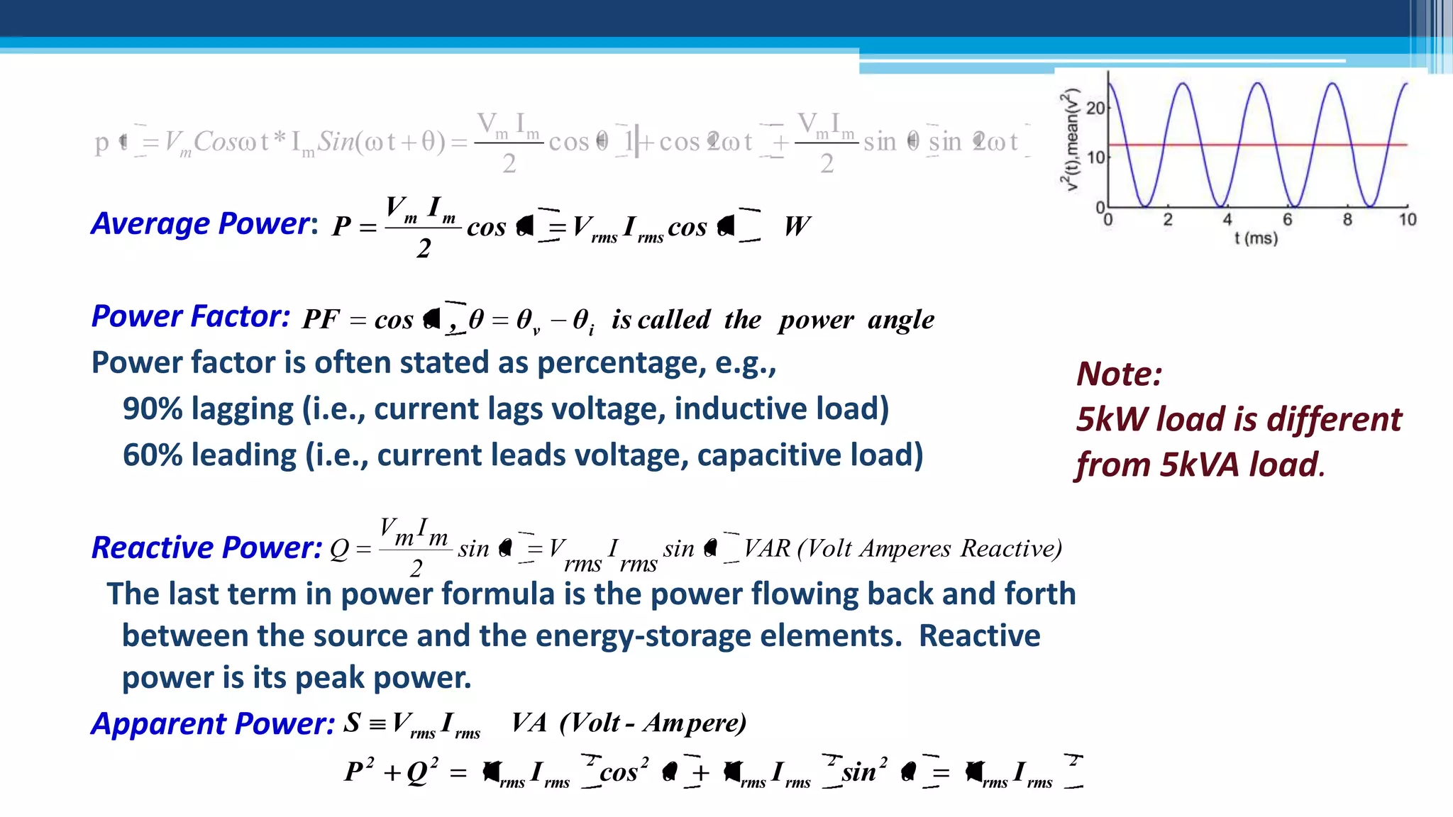
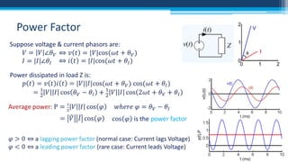
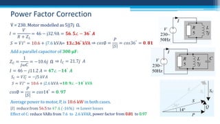
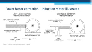
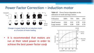
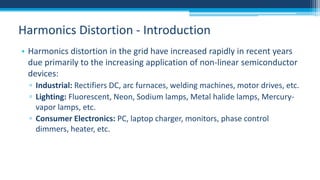
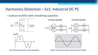
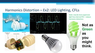
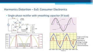
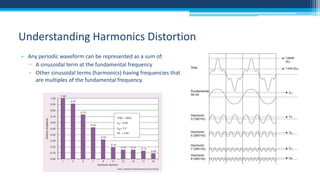


The document discusses electrical power concepts such as average power, power factor, reactive power, and apparent power, as well as the effects of harmonics distortion from various devices. Specific examples including induction motors and rectifiers illustrate how power factor correction can improve efficiency and reduce reactive power. The document emphasizes the importance of managing harmonics to prevent inefficiencies and operational issues in electrical systems.