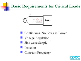
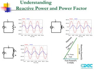
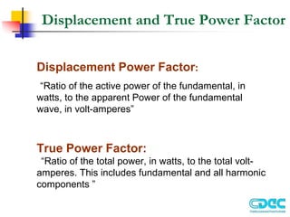
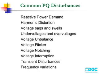
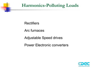
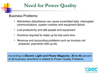
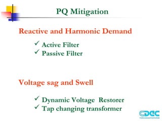
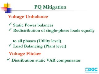
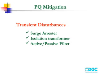
2. Basic Requirements for Critical Loads
Continuous, No Break in Power
Voltage Regulation
Sine wave Supply
Isolation
Constant Frequency
Load
Vs
Is
3. Understanding
Reactive Power and Power Factor
Vs
Is
R
Is
Vs
XL
Reactive
Power(Q)
in
VAR
Apparent
Power(S) in
VA
Imp. Phase
Angle
True Power(P)
in Watts
XL
Vs
Is
R
4. Displacement and True Power Factor
Displacement Power Factor:
“Ratio of the active power of the fundamental, in
watts, to the apparent Power of the fundamental
wave, in volt-amperes”
True Power Factor:
“Ratio of the total power, in watts, to the total volt-
amperes. This includes fundamental and all harmonic
components ”
7. Total Harmonic Distortion
Defines the total harmonic content of current or voltage
Ratio of the RMS of the harmonic content to the RMS of the
Fundamental, as % of Fundamental
THD =
sum of squares of amplitudes of all harmonics
square of amplitude of fundamental
x 100
Mathematically,
THD of a voltage wave form can be defined as,
THD =
V
V
100
x
h
h
h
2
1
2
2
=
=∞
∑
8. Power Quality
Supply Voltage at load must
The Voltage at any point in the distribution system is uniquely
described by
Where
v,f are constants (declared Value) for all t
)
2
(
2
V(t) ft
VSin π
=
have fundamental component only
be balanced
have declared magnitude under all conditions
9. PQ affected by Polluting Load
Polluting
Load
A
B
PCC
Distorted
voltage
Pure Sinusoidal
Line Impedance ZL
10. Common PQ Disturbances
Reactive Power Demand
Harmonic Distortion
Voltage sags and swells
Undervoltages and overvoltages
Voltage Unbalance
Voltage Flicker
Voltage Notching
Voltage Interruption
Transient Disturbances
Frequency variations
12. Harmonics-FFT Analysis
Current drawn by PC
Harmonic Spectrum of PC
Current Waveform
6 Pulse Converter/Battery Charger
Harmonic Spectrum of 6 Pulse
Converter/Battery Charger
13. Implication of
Reactive and Harmonics currents
Oversize of all installation equipments to transmit Reactive and
Harmonic currents namely
Transformer
Cables
Circuit breakers & distribution switch boards
Neutral overloads
Increase in Transmission & Distribution loss
Reduction in voltage stability margin
Overheating and loss of life & equipments
Major Increase in cost
14. Voltage sags and swells
• Reduction in the ac voltage, at the power frequency, for durations
from a half-cycle to a few seconds.
• Voltage Sag is Characterized by two parameters – Magnitude and
Duration
• Power Electronics Loads are Sensitive to Voltage Sags
15. Causes of Voltage sags and swells
Causes for Sag
Motor Starting
Transformer Energization
Transmission Faults
Causes for Swell
Single line to ground fault
Removing a large load /
adding a large
capacitor bank
0 1 2 3 4 5 6 7 8 9 10 11
190
195
200
205
210
215
220
RMS
voltage
in
V
Time in Cycles
0 5 10 15 20 25
10
10.1
10.2
10.3
10.4
10.5
10.6
10.7
10.8
10.9
11
Time in Cycles
RMS
voltage
in
kV
Voltage sag due to Motor Starting
Voltage sag due to Transformer
Energization
16. Voltage Unbalance
Definition
In a balanced sinusoidal supply system the three line-neutral voltages
are equal in magnitude and are phase displaced from each other by 120
degrees
Causes for Unbalance
Unequal system impedances
Unequal distribution of
single-phase loads
Phase to Phase loads
Unbalanced Three phase loads
Va
Vb
Vc
1200
1200
1200
Va
Vb
Vc
1200
1210
1190
Balanced System Unbalanced System
17. Effect of Voltage Unbalance
Induction Motor drive
• Overheating and loss of Insulation life
• Reduced Motor Efficiency
• Noisy in their operation due Torque and speed pulsation
• Motor derating factor
NEMA Induction motor derating curve
18. Effect of Voltage Unbalance
AC Variable Speed drive
M
3Ø Diode Rectifier
Line Current of 3Ø diode
Rectifier for Balanced Input
Line Current of 3Ø diode
Rectifier for 5%unbalanced Input
Line Current of 3Ø diode Rectifier
for 15%unbalanced Input
• Draws uncharacteristic triplen harmonics
• Triplen harmonic current can lead to undesirable
harmonic problems
• Excessive thermal stress on diodes
19. Voltage Flicker
Definition
Repetitive or random variations of the voltage envelope modulated at
frequencies less than 25 Hz, which the human eye can detect as a
variation in the lamp intensity of a standard bulb due to sudden changes
in the real and reactive Power drawn by a load
Voltage waveform showing flicker created by an arc furnace
20. Voltage Flicker
Effect
lamp flicker
Human eye is most sensitive to voltage waveform
modulation around a frequency of 6-8Hz.
Causes
Induction Motor drive
• Arc furnaces
• Arc welders
• Frequent motor starts
23. Transient Disturbances
Transient disturbances are caused by the injection of
energy by switching or by lightning
Causes
Lightning
Capacitor Switching
Load switching
Oscillatory transient waveform caused by capacitor energizing
24. Need for Power Quality
Business Problems:
• Momentary disturbance can cause scrambled data, interrupted
communications, system crashes and equipment failure
• Lost productivity and idle people and equipment
• Overtime required to make up for lost work time
• Revenue and accounting problems such as invoices not
prepared, payments held up etc
According to Electric Light and Power Magazine, 30 to 40 percent
of all business downtime is related to Power Quality Problems
25. IEEE 519 Harmonic Standard
IEEE 519 “Recommended Practices and Requirements for
Harmonic Control in Electric Power Systems”
Specifies load current harmonic limits at PCC
Specifies supply voltage harmonic limits at PCC
HARMONIC CURRENT DISTORTION LIMITS IN % OF IL
V<69 kV
h 11
< 11<h<17 17<h<23 23<h<35 35<h TDD
4.0 2.0 1.5 0.6 0.3 5.0
7.0 3.5 2.5 1.0 0.5 8.0
10.0 4.5 4.0 1.5 0.7 12.0
12.0 5.5 5.0 2.0 1.0 15.0
ISC/ IL
< 20
20-50
50-100
100-1000
> 1000 15.0 7.0 6.0 2.5 1.4 20.0
26. PQ Mitigation
Reactive and Harmonic Demand
Active Filter
Passive Filter
Voltage sag and Swell
Dynamic Voltage Restorer
Tap changing transformer
27. PQ Mitigation
Voltage Unbalance
Static Power balancer
Redistribution of single-phase loads equally
to all phases (Utility level).
Load Balancing (Plant level)
Voltage Flicker
Distribution static VAR compensator