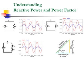
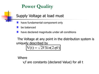
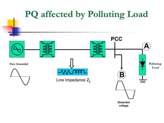
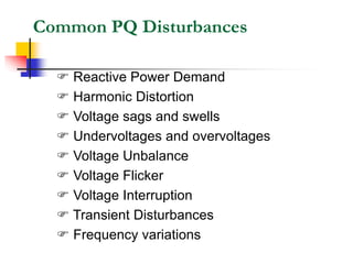
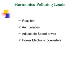
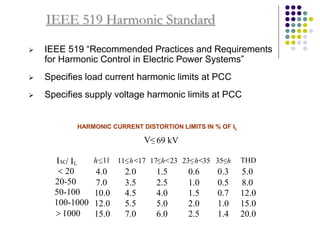
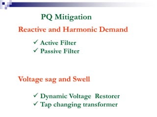
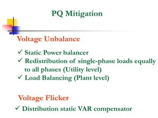
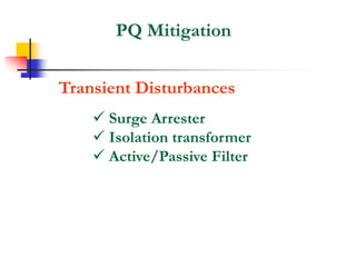
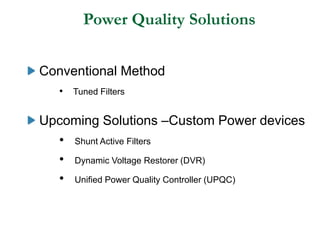
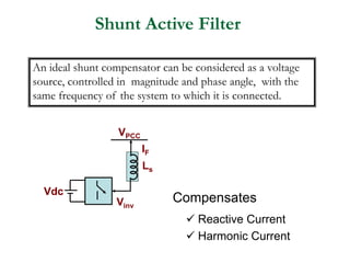
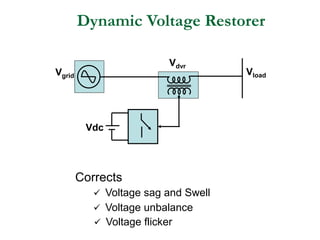
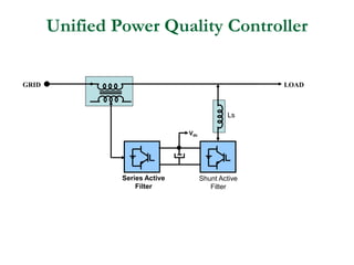
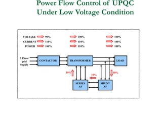
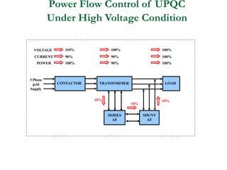
Presented by
KRISHNAKUMAR.R
ASSISTANT ENGINEER,
SWITCHYARD SUB DIVISION ,
MOOLAMATTOM.
Power Quality Issues
Organisation of the Talk
Introduction
Understanding
 Reactive Power
 Harmonic Power
 Power Factor and Crest Factor
Power Quality ( PQ )
 Common PQ Disturbances
 Causes for PQ Disturbances
 Need for PQ
 PQ Standards
Power Quality Mitigation Techniques
Conclusion
Basic Requirements for Critical
Loads
 Continuous, No Break in Power
 Voltage Regulation
 Sine wave Supply
 Isolation
 Constant Frequency
Load
Vs
Is
Understanding
Reactive Power and Power Factor
Vs
Is
R
Is
Vs XL
Reactive
Power(Q)
in
VAR
Imp. Phase
Angle
True Power(P)
in Watts
XL
Vs
Is
R
Displacement and True Power Factor
Displacement Power Factor:
“Ratio of the active power of the fundamental, in
watts, to the apparent Power of the fundamental
wave, in volt-amperes”
True Power Factor:
“Ratio of the total power, in watts, to the total volt-
amperes. This includes fundamental and all harmonic
components ”
Understanding Crest Factor
Non
Linear
Load
Vs
Is
Current drawn by single Phase diode rectifier
Crest Factor = --------------------------
Peak Amplitude
RMS Value
Understanding Harmonics
Non
Linear
Load
Vs
Is
Deviation from a perfect sine wave can be represented by Harmonics.
Sinusoidal Component having a frequency that is an integral
multiple of the Fundamental frequency.
Total Harmonic Distortion
 Defines the total harmonic content of current or voltage
 Ratio of the RMS of the harmonic content to the RMS of the
Fundamental, as % of Fundamental
THD =
sum of squares of amplitudes of all harmonics
square of amplitude of fundamental
x 100
Mathematically,THD of a voltage wave form can be defined as,
THD =
V
V
100
x
h
h
h
2
1
2
2
=
=

Power Quality
Supply Voltage at load must
The Voltage at any point in the distribution system is
uniquely described by
Where
v,f are constants (declared Value) for all t
)
2
(
2
V(t) ft
VSin 
=
have fundamental component only
be balanced
have declared magnitude under all conditions
PQ affected by Polluting Load
Polluting
Load
A
B
PCC
Distorted
voltage
Pure Sinusoidal
Line Impedance ZL
Common PQ Disturbances
 Reactive Power Demand
 Harmonic Distortion
 Voltage sags and swells
 Undervoltages and overvoltages
 Voltage Unbalance
 Voltage Flicker
 Voltage Interruption
 Transient Disturbances
 Frequency variations
Harmonics-Polluting Loads
 Rectifiers
 Arc furnaces
 Adjustable Speed drives
 Power Electronic converters
Harmonics-FFT Analysis
Current drawn by PC
Harmonic Spectrum of PC
Current Waveform
6 Pulse Converter/Battery Charger
Harmonic Spectrum of 6 Pulse
Converter/Battery Charger
Implication of
Reactive and Harmonics currents
Oversize of all installation equipments to transmit Reactive and
Harmonic currents namely
Transformer
Cables
Circuit breakers & distribution switch boards
Neutral overloads
Increase in Transmission & Distribution loss
Overheating and loss of life & equipments
Major Increase in cost
Voltage sags and swells
 Reduction in the ac voltage, at the power frequency, for durations
from a half-cycle to a few seconds.
 Voltage Sag is Characterized by two parameters – Magnitude and
Duration
 Power Electronics Loads are Sensitive to Voltage Sags
Causes of Voltage sags and swells
Causes for Sag
 Motor Starting
 Transformer Energization
 Transmission Faults
Causes for Swell
 Single line to ground fault
 Removing a large load /
adding a large capacitor bank
0 1 2 3 4 5 6 7 8 9 10 11
190
195
200
205
210
215
220
RMS
voltage
in
V
Time in Cycles
0 5 10 15 20 25
10
10.1
10.2
10.3
10.4
10.5
10.6
10.7
10.8
10.9
11
Time in Cycles
RMS
voltage
in
kV
Voltage sag due to Motor Starting
Voltage sag due to Transformer
Energization
Voltage Unbalance
Definition
In a balanced sinusoidal supply system the three line-neutral voltages
are equal in magnitude and are phase displaced from each other by 120
degrees
Causes for Unbalance
 Unequal system impedances
 Unequal distribution of
single-phase loads
Phase to Phase loads
Unbalanced Three phase loads
Va
Vb
Vc
1200
1200
1200
Va
Vb
Vc
1200
1210
1190
Balanced System Unbalanced System
Effect of Voltage Unbalance
 Induction Motor drive
• Overheating and loss of Insulation life
• Reduced Motor Efficiency
• Noisy in their operation due Torque and speed pulsation
• Motor derating factor
NEMA Induction motor derating curve
Effect of Voltage Unbalance
 AC Variable Speed drive
M
3Ø Diode Rectifier
Line Current of 3Ø diode
Rectifier for Balanced Input
Line Current of 3Ø diode
Rectifier for 5%unbalanced Input
Line Current of 3Ø diode Rectifier
for 15%unbalanced Input
• Draws uncharacteristic triplen harmonics
• Triplen harmonic current can lead to undesirable
harmonic problems
• Excessive thermal stress on diodes
Voltage Flicker
Definition
Repetitive or random variations of the voltage envelope modulated at
frequencies less than 25 Hz, which the human eye can detect as a
variation in the lamp intensity of a standard bulb due to sudden changes
in the real and reactive Power drawn by a load
Voltage waveform showing flicker created by an arc furnace
Voltage Flicker
Effect
 lamp flicker
Human eye is most sensitive to voltage waveform
modulation around a frequency of 6-8Hz.
Causes
 Induction Motor drive
• Arc furnaces
• Arc welders
• Frequent motor starts
Voltage Interruption
Complete loss of electrical supply
Cause
 Transmission Fault clearing time
• Opening / Recloser of circuit breaker
Transient Disturbances
Transient disturbances are caused by the injection of
energy by switching or by lightning
Causes
 Lightning
 Capacitor Switching
 Load switching
Oscillatory transient waveform caused by capacitor energizing
Need for Power Quality
Business Problems:
• Momentary disturbance can cause scrambled data, interrupted
communications, system crashes and equipment failure
• Lost productivity and idle people and equipment
• Overtime required to make up for lost work time
• Revenue and accounting problems such as invoices not
prepared, payments held up etc
According to Electric Light and Power Magazine, 30 to 40 percent
of all business downtime is related to Power Quality Problems
IEEE 519 Harmonic Standard
 IEEE 519 “Recommended Practices and Requirements
for Harmonic Control in Electric Power Systems”
 Specifies load current harmonic limits at PCC
 Specifies supply voltage harmonic limits at PCC
HARMONIC CURRENT DISTORTION LIMITS IN % OF IL
V< 69 kV
h 11
< 11<h<17 17<h<23 23<h<35 35<h THD
4.0 2.0 1.5 0.6 0.3 5.0
7.0 3.5 2.5 1.0 0.5 8.0
10.0 4.5 4.0 1.5 0.7 12.0
12.0 5.5 5.0 2.0 1.0 15.0
ISC/ IL
< 20
20-50
50-100
100-1000
> 1000 15.0 7.0 6.0 2.5 1.4 20.0
PQ Mitigation
Reactive and Harmonic Demand
 Active Filter
 Passive Filter
Voltage sag and Swell
 Dynamic Voltage Restorer
 Tap changing transformer
PQ Mitigation
Voltage Unbalance
 Static Power balancer
 Redistribution of single-phase loads equally
to all phases (Utility level).
 Load Balancing (Plant level)
Voltage Flicker
 Distribution static VAR compensator
PQ Mitigation
Transient Disturbances
 Surge Arrester
 Isolation transformer
 Active/Passive Filter
References
 IEEE 519 “Recommended Practices and
Requirements for Harmonic Control in
Electric Power Systems”
 www.ieeexplore.ieee.org
Thank You
Power Quality Solutions
Conventional Method
• Tuned Filters
Upcoming Solutions –Custom Power devices
• Shunt Active Filters
• Dynamic Voltage Restorer (DVR)
• Unified Power Quality Controller (UPQC)
Shunt Active Filter
Vdc
VPCC
IF
Vinv
Ls
An ideal shunt compensator can be considered as a voltage
source, controlled in magnitude and phase angle, with the
same frequency of the system to which it is connected.
Compensates
 Reactive Current
 Harmonic Current
Dynamic Voltage Restorer
Vdc
Vload
Vdvr
Vgrid
Corrects
 Voltage sag and Swell
 Voltage unbalance
 Voltage flicker
Unified Power Quality Controller
GRID LOAD
Vdc
Series Active
Filter
Shunt Active
Filter
Ls
Power Flow Control of UPQC
Under Low Voltage Condition
CONTACTOR TRANSFORMER LOAD
SHUNT
AF
SERIES
AF
3 Phase
grid
Supply
VOLTAGE
CURRENT
POWER
90%
110%
100%
10%
100%
110%
110%
100%
100%
100%
10%
10%
Power Flow Control of UPQC
Under High Voltage Condition
CONTACTOR TRANSFORMER LOAD
SHUNT
AF
SERIES
AF
3 Phase
grid
Supply
VOLTAGE
CURRENT
POWER
110%
90%
100%
100%
90%
90%
10%
100%
100%
100%
10%
10%
• THE END.

Power Quality Issues Detailed Analysis.PPT

  • 1.
    Presented by KRISHNAKUMAR.R ASSISTANT ENGINEER, SWITCHYARDSUB DIVISION , MOOLAMATTOM. Power Quality Issues
  • 2.
    Organisation of theTalk Introduction Understanding  Reactive Power  Harmonic Power  Power Factor and Crest Factor Power Quality ( PQ )  Common PQ Disturbances  Causes for PQ Disturbances  Need for PQ  PQ Standards Power Quality Mitigation Techniques Conclusion
  • 3.
    Basic Requirements forCritical Loads  Continuous, No Break in Power  Voltage Regulation  Sine wave Supply  Isolation  Constant Frequency Load Vs Is
  • 4.
    Understanding Reactive Power andPower Factor Vs Is R Is Vs XL Reactive Power(Q) in VAR Imp. Phase Angle True Power(P) in Watts XL Vs Is R
  • 5.
    Displacement and TruePower Factor Displacement Power Factor: “Ratio of the active power of the fundamental, in watts, to the apparent Power of the fundamental wave, in volt-amperes” True Power Factor: “Ratio of the total power, in watts, to the total volt- amperes. This includes fundamental and all harmonic components ”
  • 6.
    Understanding Crest Factor Non Linear Load Vs Is Currentdrawn by single Phase diode rectifier Crest Factor = -------------------------- Peak Amplitude RMS Value
  • 7.
    Understanding Harmonics Non Linear Load Vs Is Deviation froma perfect sine wave can be represented by Harmonics. Sinusoidal Component having a frequency that is an integral multiple of the Fundamental frequency.
  • 8.
    Total Harmonic Distortion Defines the total harmonic content of current or voltage  Ratio of the RMS of the harmonic content to the RMS of the Fundamental, as % of Fundamental THD = sum of squares of amplitudes of all harmonics square of amplitude of fundamental x 100 Mathematically,THD of a voltage wave form can be defined as, THD = V V 100 x h h h 2 1 2 2 = = 
  • 9.
    Power Quality Supply Voltageat load must The Voltage at any point in the distribution system is uniquely described by Where v,f are constants (declared Value) for all t ) 2 ( 2 V(t) ft VSin  = have fundamental component only be balanced have declared magnitude under all conditions
  • 10.
    PQ affected byPolluting Load Polluting Load A B PCC Distorted voltage Pure Sinusoidal Line Impedance ZL
  • 11.
    Common PQ Disturbances Reactive Power Demand  Harmonic Distortion  Voltage sags and swells  Undervoltages and overvoltages  Voltage Unbalance  Voltage Flicker  Voltage Interruption  Transient Disturbances  Frequency variations
  • 12.
    Harmonics-Polluting Loads  Rectifiers Arc furnaces  Adjustable Speed drives  Power Electronic converters
  • 13.
    Harmonics-FFT Analysis Current drawnby PC Harmonic Spectrum of PC Current Waveform 6 Pulse Converter/Battery Charger Harmonic Spectrum of 6 Pulse Converter/Battery Charger
  • 14.
    Implication of Reactive andHarmonics currents Oversize of all installation equipments to transmit Reactive and Harmonic currents namely Transformer Cables Circuit breakers & distribution switch boards Neutral overloads Increase in Transmission & Distribution loss Overheating and loss of life & equipments Major Increase in cost
  • 15.
    Voltage sags andswells  Reduction in the ac voltage, at the power frequency, for durations from a half-cycle to a few seconds.  Voltage Sag is Characterized by two parameters – Magnitude and Duration  Power Electronics Loads are Sensitive to Voltage Sags
  • 16.
    Causes of Voltagesags and swells Causes for Sag  Motor Starting  Transformer Energization  Transmission Faults Causes for Swell  Single line to ground fault  Removing a large load / adding a large capacitor bank 0 1 2 3 4 5 6 7 8 9 10 11 190 195 200 205 210 215 220 RMS voltage in V Time in Cycles 0 5 10 15 20 25 10 10.1 10.2 10.3 10.4 10.5 10.6 10.7 10.8 10.9 11 Time in Cycles RMS voltage in kV Voltage sag due to Motor Starting Voltage sag due to Transformer Energization
  • 17.
    Voltage Unbalance Definition In abalanced sinusoidal supply system the three line-neutral voltages are equal in magnitude and are phase displaced from each other by 120 degrees Causes for Unbalance  Unequal system impedances  Unequal distribution of single-phase loads Phase to Phase loads Unbalanced Three phase loads Va Vb Vc 1200 1200 1200 Va Vb Vc 1200 1210 1190 Balanced System Unbalanced System
  • 18.
    Effect of VoltageUnbalance  Induction Motor drive • Overheating and loss of Insulation life • Reduced Motor Efficiency • Noisy in their operation due Torque and speed pulsation • Motor derating factor NEMA Induction motor derating curve
  • 19.
    Effect of VoltageUnbalance  AC Variable Speed drive M 3Ø Diode Rectifier Line Current of 3Ø diode Rectifier for Balanced Input Line Current of 3Ø diode Rectifier for 5%unbalanced Input Line Current of 3Ø diode Rectifier for 15%unbalanced Input • Draws uncharacteristic triplen harmonics • Triplen harmonic current can lead to undesirable harmonic problems • Excessive thermal stress on diodes
  • 20.
    Voltage Flicker Definition Repetitive orrandom variations of the voltage envelope modulated at frequencies less than 25 Hz, which the human eye can detect as a variation in the lamp intensity of a standard bulb due to sudden changes in the real and reactive Power drawn by a load Voltage waveform showing flicker created by an arc furnace
  • 21.
    Voltage Flicker Effect  lampflicker Human eye is most sensitive to voltage waveform modulation around a frequency of 6-8Hz. Causes  Induction Motor drive • Arc furnaces • Arc welders • Frequent motor starts
  • 22.
    Voltage Interruption Complete lossof electrical supply Cause  Transmission Fault clearing time • Opening / Recloser of circuit breaker
  • 23.
    Transient Disturbances Transient disturbancesare caused by the injection of energy by switching or by lightning Causes  Lightning  Capacitor Switching  Load switching Oscillatory transient waveform caused by capacitor energizing
  • 24.
    Need for PowerQuality Business Problems: • Momentary disturbance can cause scrambled data, interrupted communications, system crashes and equipment failure • Lost productivity and idle people and equipment • Overtime required to make up for lost work time • Revenue and accounting problems such as invoices not prepared, payments held up etc According to Electric Light and Power Magazine, 30 to 40 percent of all business downtime is related to Power Quality Problems
  • 25.
    IEEE 519 HarmonicStandard  IEEE 519 “Recommended Practices and Requirements for Harmonic Control in Electric Power Systems”  Specifies load current harmonic limits at PCC  Specifies supply voltage harmonic limits at PCC HARMONIC CURRENT DISTORTION LIMITS IN % OF IL V< 69 kV h 11 < 11<h<17 17<h<23 23<h<35 35<h THD 4.0 2.0 1.5 0.6 0.3 5.0 7.0 3.5 2.5 1.0 0.5 8.0 10.0 4.5 4.0 1.5 0.7 12.0 12.0 5.5 5.0 2.0 1.0 15.0 ISC/ IL < 20 20-50 50-100 100-1000 > 1000 15.0 7.0 6.0 2.5 1.4 20.0
  • 26.
    PQ Mitigation Reactive andHarmonic Demand  Active Filter  Passive Filter Voltage sag and Swell  Dynamic Voltage Restorer  Tap changing transformer
  • 27.
    PQ Mitigation Voltage Unbalance Static Power balancer  Redistribution of single-phase loads equally to all phases (Utility level).  Load Balancing (Plant level) Voltage Flicker  Distribution static VAR compensator
  • 28.
    PQ Mitigation Transient Disturbances Surge Arrester  Isolation transformer  Active/Passive Filter
  • 29.
    References  IEEE 519“Recommended Practices and Requirements for Harmonic Control in Electric Power Systems”  www.ieeexplore.ieee.org
  • 30.
  • 32.
    Power Quality Solutions ConventionalMethod • Tuned Filters Upcoming Solutions –Custom Power devices • Shunt Active Filters • Dynamic Voltage Restorer (DVR) • Unified Power Quality Controller (UPQC)
  • 33.
    Shunt Active Filter Vdc VPCC IF Vinv Ls Anideal shunt compensator can be considered as a voltage source, controlled in magnitude and phase angle, with the same frequency of the system to which it is connected. Compensates  Reactive Current  Harmonic Current
  • 34.
    Dynamic Voltage Restorer Vdc Vload Vdvr Vgrid Corrects Voltage sag and Swell  Voltage unbalance  Voltage flicker
  • 35.
    Unified Power QualityController GRID LOAD Vdc Series Active Filter Shunt Active Filter Ls
  • 36.
    Power Flow Controlof UPQC Under Low Voltage Condition CONTACTOR TRANSFORMER LOAD SHUNT AF SERIES AF 3 Phase grid Supply VOLTAGE CURRENT POWER 90% 110% 100% 10% 100% 110% 110% 100% 100% 100% 10% 10%
  • 37.
    Power Flow Controlof UPQC Under High Voltage Condition CONTACTOR TRANSFORMER LOAD SHUNT AF SERIES AF 3 Phase grid Supply VOLTAGE CURRENT POWER 110% 90% 100% 100% 90% 90% 10% 100% 100% 100% 10% 10%
  • 38.

Editor's Notes