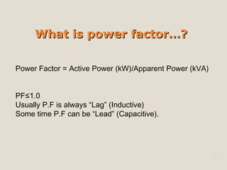
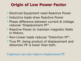
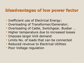
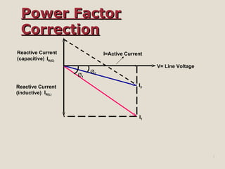
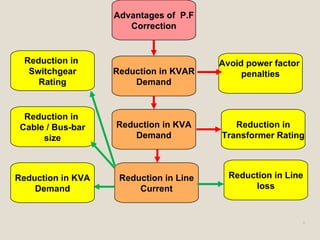
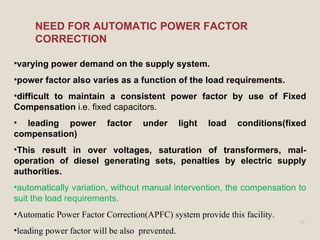
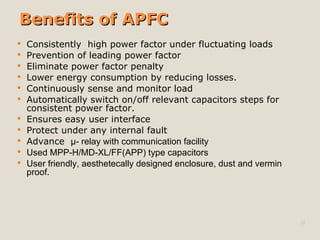
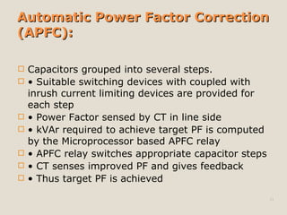
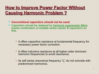
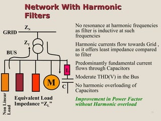
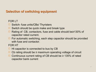
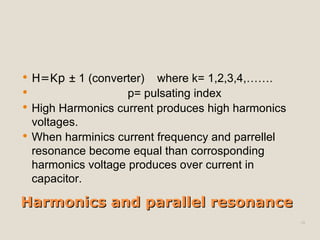
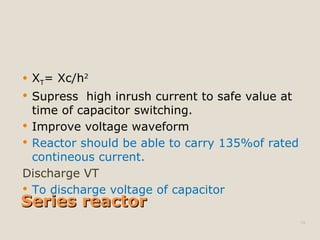
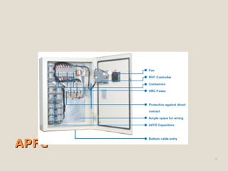
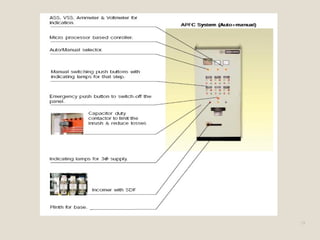
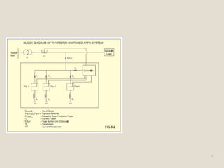
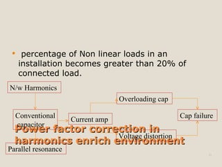
This document discusses power factor correction and automatic power factor correction (APFC) systems. It explains that power factor is the ratio of active power to apparent power and can be lagging or leading. Low power factors are caused by inductive loads and non-linear loads. APFC systems use capacitors in automatic steps controlled by a microprocessor to maintain a high power factor under varying loads without manual intervention or risk of overvoltage. This improves efficiency and reduces utility penalties and equipment loading and sizes. The document provides specifications for capacitor selection and switching equipment for APFC systems.


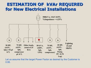
![Kvar For The Supply Transformer- For 500 kVA transformer, kVAr = 30 kVAr Kvar For Induction Motor- rating of motor = 200 HP x 0.746 = 150 kW Kvar for motor = 150*[tan(cos -1 (0.95)- tan(cos -1 (0.99)] = 104 Kvar Kvar For UPS- rating of UPS = 50 KVA* 0.7 = 35 Kw Kvar for UPS = 35 [tan(cos -1 (0.70)- tan(cos -1 (0.99)] = 25 Kvar Kvar For Others & lighting load- Kvar for UPS = 24 [tan(cos -1 (0.70)- tan(cos -1 (0.99)] = 17 Kvar Total kvar requirement = (30+104+35+25+17)kvar =211 Kvar Assuming 15% design assumption and contigency = 221*0.15=31.65 Kvar Total kvar = 242.65 kvar Kavr recommended= 250 kvar Capacitor req. (c) = Qc/V 2 (2 f) Hence Capacitor req. for UPF=10 6 * 250/(230 2 * 100 ) = 150.51 F.](https://image.slidesharecdn.com/cdocumentsandsettingsdeedesktopraviapfc-090225113101-phpapp02/85/automatic-power-factor-controller-8-320.jpg)
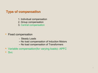
![Specification of capacitors in APFC Qkvar Degree Of Protection IP20 Ambient temperature Voltage rise should be ≤ 3.0% [ % Vc = (Q kvar *%X)/(kva)] Voltage rise due to series reactor and harmonics Size of individual capacitor banks (step requirement) Directly connected Discharge Device(Resistor, VT) to discharge the capacitor to reduce voltage to 50 volts within one minute](https://image.slidesharecdn.com/cdocumentsandsettingsdeedesktopraviapfc-090225113101-phpapp02/85/automatic-power-factor-controller-16-320.jpg)


![Kvar Presentation Ppt 8.8.08[1]](https://cdn.slidesharecdn.com/ss_thumbnails/kvarpresentationppt8-8-081-090713082239-phpapp01-thumbnail.jpg?width=640&height=640&fit=bounds)


