Download to read offline


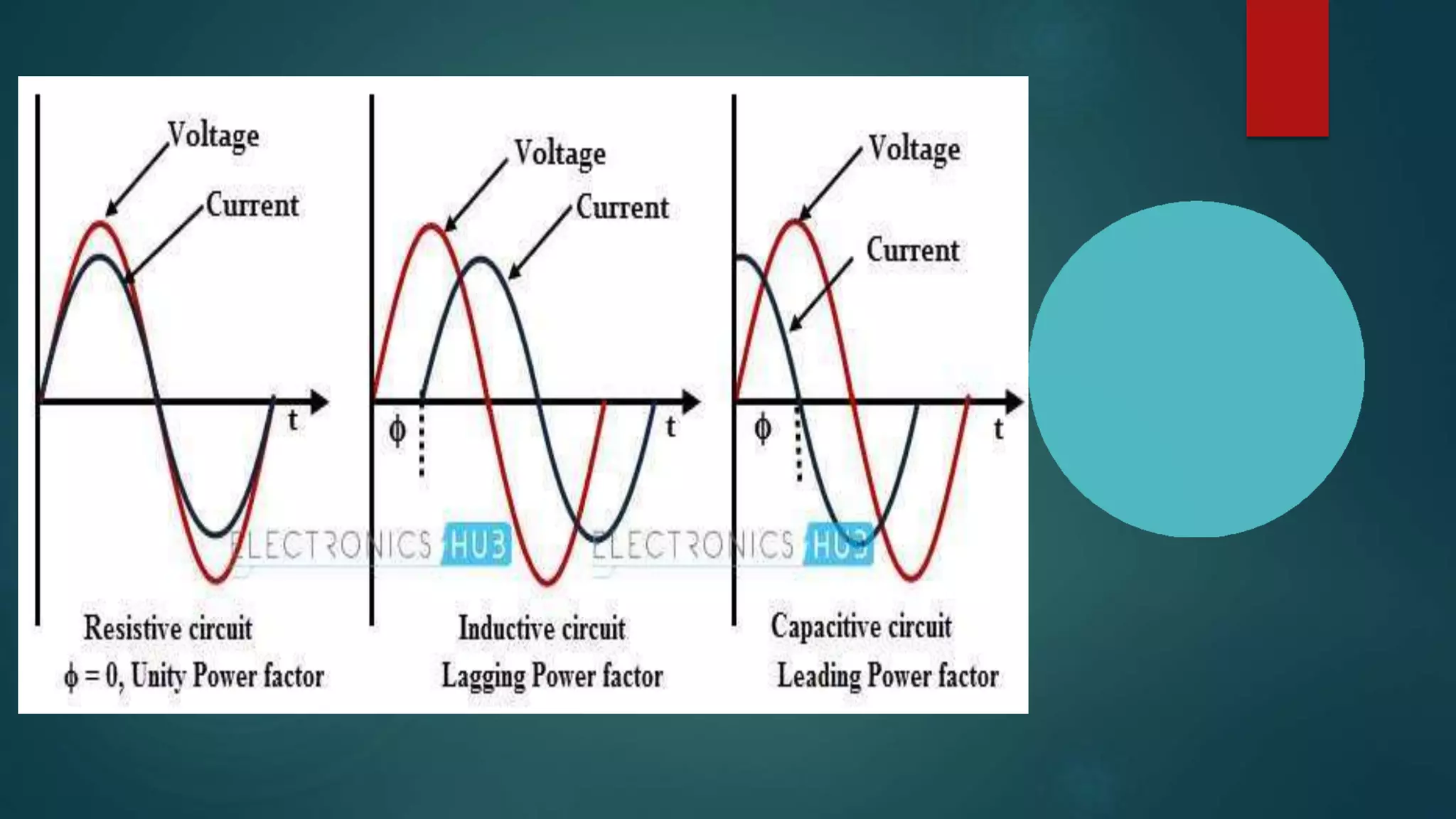
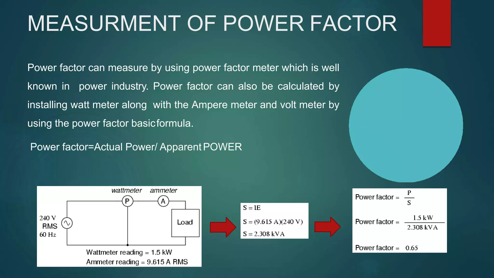


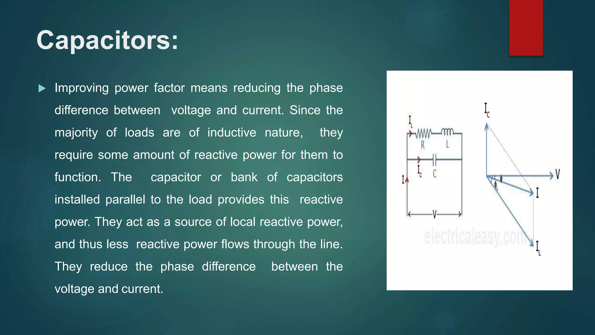
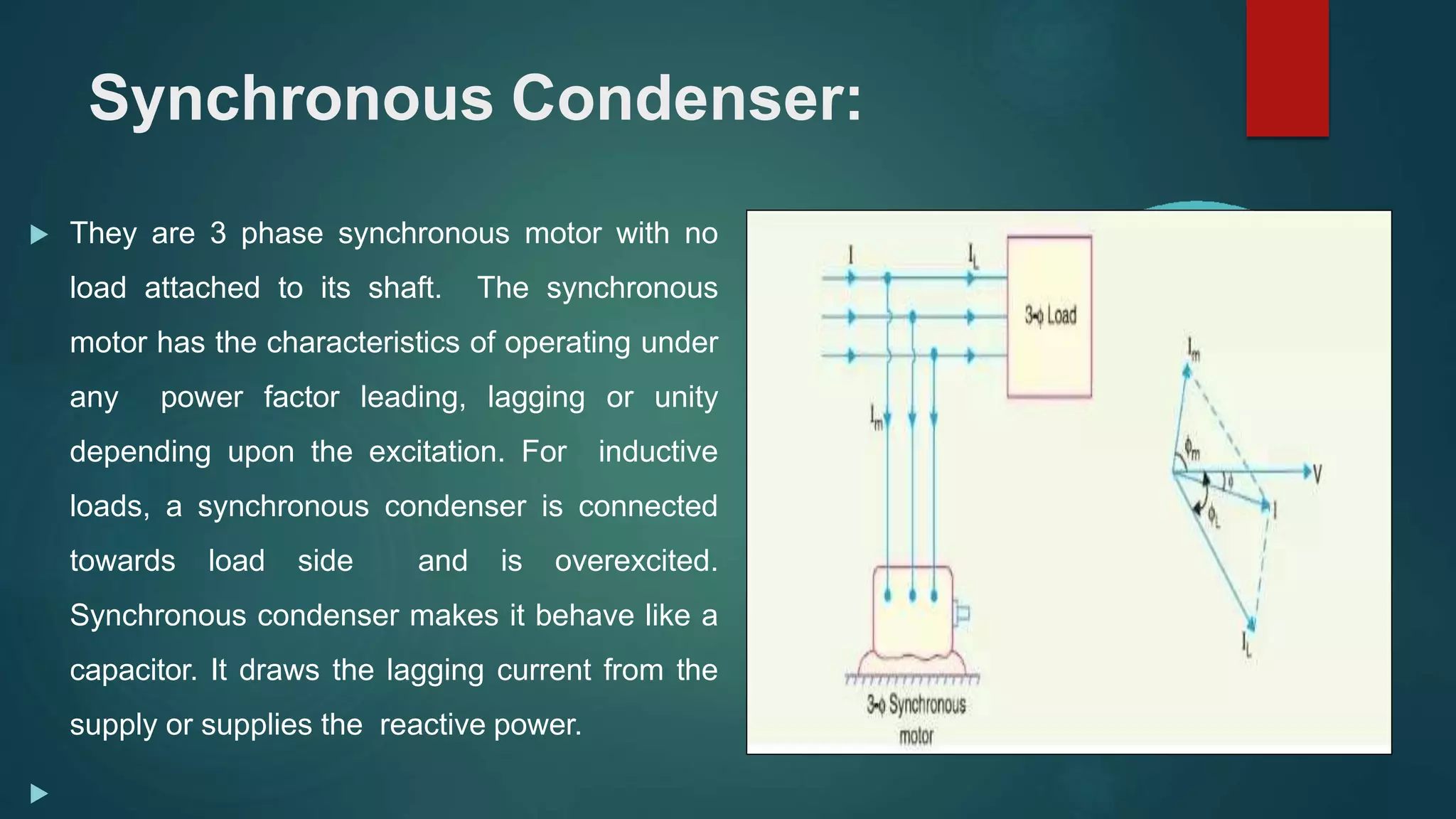
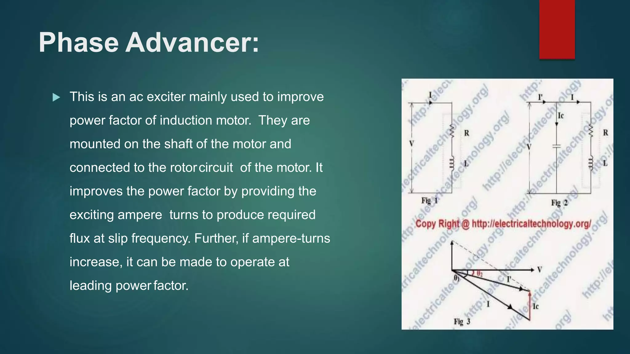

This document discusses power factor, which is the ratio of actual power to apparent power in an electrical system. It defines power factor and different types, and describes how power factor is measured. Having a low power factor causes disadvantages like increased losses and costs. Various methods to improve power factor are presented, including using capacitors, static VAR compensators, synchronous condensers, and phase advancers. Improving power factor provides benefits such as reduced losses and increased system capacity.