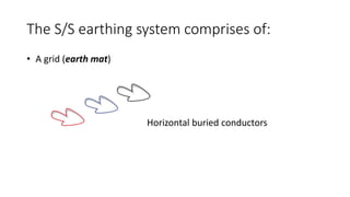
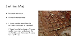
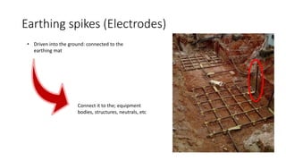
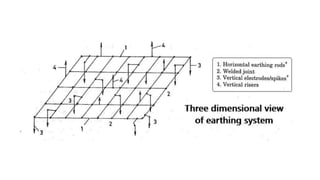
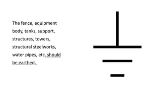
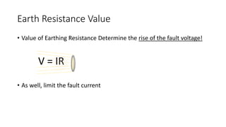
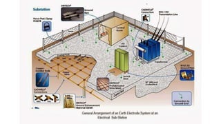
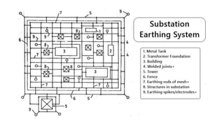
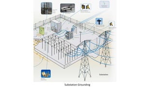
Substation Earthing System
Earthing Mat
The S/S earthing system comprises of:
• A grid (earth mat)
Horizontal buried conductors
Functions of grounding system in the S/S
• Ensure safety of personnel due to electric shocks.
• Provide grounding path (Neutral grounding).
• Discharge over-voltages (ground path for surge arrestors).
• Provide path for faults (Phase-Ground).
• Provide earth connections to the non-current carrying objects in the
s/s.
Earthing Mat
• Buried below ground level
• Connected conductors
• If the soil have low resistivity>> the
earthing resistance will be low as well.
• If the soil have high resistivity>> Then we
need to insert more conductors in the
mesh and connect them closer (To create
lower resistance)
Earthing spikes (Electrodes)
• Driven into the ground: connected to the
earthing mat
Connect it to the; equipment
bodies, structures, neutrals, etc
The fence, equipment
body, tanks, support,
structures, towers,
structural steelworks,
water pipes, etc. should
be earthed.
Earth Resistance Value
• Value of Earthing Resistance Determine the rise of the fault voltage!
• As well, limit the fault current
V = IR
Criteria of design S/S earthing system
• Low step voltage
• Low touch voltage
• Low earth resistance
Touch Voltage (E-Touch)
Step Voltage (E-Step)
Substation Grounding

Substation Earthing

  • 1.
  • 2.
    The S/S earthingsystem comprises of: • A grid (earth mat) Horizontal buried conductors
  • 3.
    Functions of groundingsystem in the S/S • Ensure safety of personnel due to electric shocks. • Provide grounding path (Neutral grounding). • Discharge over-voltages (ground path for surge arrestors). • Provide path for faults (Phase-Ground). • Provide earth connections to the non-current carrying objects in the s/s.
  • 4.
    Earthing Mat • Buriedbelow ground level • Connected conductors • If the soil have low resistivity>> the earthing resistance will be low as well. • If the soil have high resistivity>> Then we need to insert more conductors in the mesh and connect them closer (To create lower resistance)
  • 5.
    Earthing spikes (Electrodes) •Driven into the ground: connected to the earthing mat Connect it to the; equipment bodies, structures, neutrals, etc
  • 7.
    The fence, equipment body,tanks, support, structures, towers, structural steelworks, water pipes, etc. should be earthed.
  • 8.
    Earth Resistance Value •Value of Earthing Resistance Determine the rise of the fault voltage! • As well, limit the fault current V = IR
  • 11.
    Criteria of designS/S earthing system • Low step voltage • Low touch voltage • Low earth resistance
  • 12.
  • 13.
  • 14.