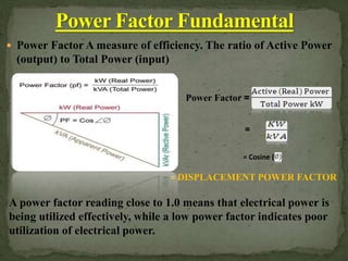
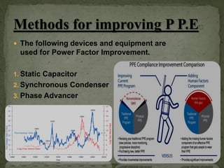
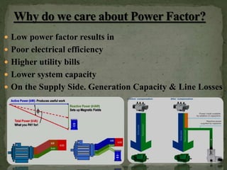
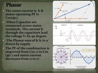
Group Name: অনির্বাি
Port City International University
Excellence In Higher Education
UGC & Govt. Approved university at khulshi in Chittagong
A leading Global University meeting the challenges of the fast changing world
Name
Mintazur Rahaman
Narayan Datta
Tamzidul karim
Dibbharaj Sarkar
Mohidul Islam
 Working /Active Power: Normally measured in
kilowatts (kW). It does the "work" for the system--
providing the motion, torque, heat, or whatever else is
required.
 Reactive Power: Normally measured in kilovolt-
amperes reactive (kVAR), doesn't do useful "work." It
simply sustains the electromagnetic field.
 Apparent Power: Normally measured in kilovolt-
amperes (kVA). Working Power and Reactive Power
together make up apparent power
 Power Factor A measure of efficiency. The ratio of Active Power
(output) to Total Power (input)
Power Factor =
= DISPLACEMENT POWER FACTOR
=
= Cosine (
A power factor reading close to 1.0 means that electrical power is
being utilized effectively, while a low power factor indicates poor
utilization of electrical power.
 1. Most of the motors
used in industries are
of induction type,
which have low lagging
pf
 2. Lamps, discharge
lamps operate at low
lagging pf
 3 Transformer system
work at low lagging pf
 4. Load on the system
is varying which results
in decreasing or low pf
 Power Factor is a measure of the electrical
systems efficiency The total electrical power
(Kilo Volt Amperes or kVA) used in an electrical
system by an industrial .
 AC POWER FLOW HAS TWO COMPONENTS:
 REAL POWER OR ACTIVE POWER (P) EXPRESSED IN WATTS (W)
 REACTIVE POWER (Q), USUALLY EXPRESSED IN REACTIVE VOLT-
AMPERES (VAR)
 THESE ARE COMBINED TO THE COMPLEX POWER (S) EXPRESSED VOLT-
AMPERES (VA). THE MAGNITUDE OF THE COMPLEX POWER IS THE
APPARENT POWER (|S|), ALSO EXPRESSED IN VOLT-AMPERES (VA).
 THE POWER FACTOR IS DEFINED AS THE RATIO OF REAL POWER TO
APPARENT POWER. AS POWER IS TRANSFERRED ALONG A
TRANSMISSION LINE
 IF Θ IS THE PHASE ANGLE BETWEEN THE CURRENT AND VOLTAGE,
THEN THE POWER FACTOR IS EQUAL TO THE COSINE OF THE ANGLE,
 The following devices and equipment are
used for Power Factor Improvement.
1. Static Capacitor
2. Synchronous Condenser
3. Phase Advancer
 1. Lower the pf, higher is the load current required
 2. Lower the pf, kvA rating of the equipment has to be
more which means the equipment has to be larger and
expensive
 3. To transmit or distribute a fixed amount of power at
constant voltage, the conductor will have to carry more
current at LPF which means the conductor size has to
be large
 4. Large current at LPF, makes PR osses to increase
which results in poor efficiency
 5. The lagging PF reduces the handling capacity of a
elements of the system due to the reactive component
of the current
 6. Large current at LPF causes greater voltage drops in
alternators. transformers, transmission lines and
distributors poor voltage regulation
 Low power factor results in
 Poor electrical efficiency
 Higher utility bills
 Lower system capacity
 On the Supply Side. Generation Capacity & Line Losses
 Reduction in Electricity Bill due to reduced maximum
demand
 No low power factor penalty charges
 Improved Voltage Level in system due to elimination of
inductive current
 KW capacities of prime movers, alternators
transformers and transmission lines is increased
 Reduction in System losses; Efficiency of every plant
increases; Overall cost per unit decreases
 Voltage regulation of transmission lines increases i e,
voltage drop in the system improves
 Distribution capacity is augmented
 The stator current is l1 &
motor operating PF is
Cos(@1).
 .When Capacitor are
connected across stator
terminals, The current lc
through the capacitors lead
the voltage V1 by 90 degree.
 -The Phasor sum of & Ic is 11'
drawn by supply.
 The PF of the combination is
improved from Cos 1) to Cos
(@1') and stator current
decreases from 11 to 11'.
 Environmental benefit. Reduction of power
consumption due to improved energy efficiency.
Reduced power consumption means less greenhouse
gas emissions and fossil fuel depletion by power
stations.
 Reduction of electricity bills.
 Reduction of 12R losses in transformers and
distribution equipment
 Reduction of voltage drop in cables.
 Extended equipment life Reduced electrical burden
on cables and electrical components.
Power Factor Correction Capacitors (PFCC) provide an
economical means for improving Energy utilization
Thank You

Power factor

  • 1.
    Group Name: অনির্বাি PortCity International University Excellence In Higher Education UGC & Govt. Approved university at khulshi in Chittagong A leading Global University meeting the challenges of the fast changing world Name Mintazur Rahaman Narayan Datta Tamzidul karim Dibbharaj Sarkar Mohidul Islam
  • 2.
     Working /ActivePower: Normally measured in kilowatts (kW). It does the "work" for the system-- providing the motion, torque, heat, or whatever else is required.  Reactive Power: Normally measured in kilovolt- amperes reactive (kVAR), doesn't do useful "work." It simply sustains the electromagnetic field.  Apparent Power: Normally measured in kilovolt- amperes (kVA). Working Power and Reactive Power together make up apparent power
  • 3.
     Power FactorA measure of efficiency. The ratio of Active Power (output) to Total Power (input) Power Factor = = DISPLACEMENT POWER FACTOR = = Cosine ( A power factor reading close to 1.0 means that electrical power is being utilized effectively, while a low power factor indicates poor utilization of electrical power.
  • 4.
     1. Mostof the motors used in industries are of induction type, which have low lagging pf  2. Lamps, discharge lamps operate at low lagging pf  3 Transformer system work at low lagging pf  4. Load on the system is varying which results in decreasing or low pf
  • 5.
     Power Factoris a measure of the electrical systems efficiency The total electrical power (Kilo Volt Amperes or kVA) used in an electrical system by an industrial .
  • 6.
     AC POWERFLOW HAS TWO COMPONENTS:  REAL POWER OR ACTIVE POWER (P) EXPRESSED IN WATTS (W)  REACTIVE POWER (Q), USUALLY EXPRESSED IN REACTIVE VOLT- AMPERES (VAR)  THESE ARE COMBINED TO THE COMPLEX POWER (S) EXPRESSED VOLT- AMPERES (VA). THE MAGNITUDE OF THE COMPLEX POWER IS THE APPARENT POWER (|S|), ALSO EXPRESSED IN VOLT-AMPERES (VA).  THE POWER FACTOR IS DEFINED AS THE RATIO OF REAL POWER TO APPARENT POWER. AS POWER IS TRANSFERRED ALONG A TRANSMISSION LINE  IF Θ IS THE PHASE ANGLE BETWEEN THE CURRENT AND VOLTAGE, THEN THE POWER FACTOR IS EQUAL TO THE COSINE OF THE ANGLE,
  • 7.
     The followingdevices and equipment are used for Power Factor Improvement. 1. Static Capacitor 2. Synchronous Condenser 3. Phase Advancer
  • 8.
     1. Lowerthe pf, higher is the load current required  2. Lower the pf, kvA rating of the equipment has to be more which means the equipment has to be larger and expensive  3. To transmit or distribute a fixed amount of power at constant voltage, the conductor will have to carry more current at LPF which means the conductor size has to be large  4. Large current at LPF, makes PR osses to increase which results in poor efficiency  5. The lagging PF reduces the handling capacity of a elements of the system due to the reactive component of the current  6. Large current at LPF causes greater voltage drops in alternators. transformers, transmission lines and distributors poor voltage regulation
  • 9.
     Low powerfactor results in  Poor electrical efficiency  Higher utility bills  Lower system capacity  On the Supply Side. Generation Capacity & Line Losses
  • 10.
     Reduction inElectricity Bill due to reduced maximum demand  No low power factor penalty charges  Improved Voltage Level in system due to elimination of inductive current  KW capacities of prime movers, alternators transformers and transmission lines is increased  Reduction in System losses; Efficiency of every plant increases; Overall cost per unit decreases  Voltage regulation of transmission lines increases i e, voltage drop in the system improves  Distribution capacity is augmented
  • 11.
     The statorcurrent is l1 & motor operating PF is Cos(@1).  .When Capacitor are connected across stator terminals, The current lc through the capacitors lead the voltage V1 by 90 degree.  -The Phasor sum of & Ic is 11' drawn by supply.  The PF of the combination is improved from Cos 1) to Cos (@1') and stator current decreases from 11 to 11'.
  • 12.
     Environmental benefit.Reduction of power consumption due to improved energy efficiency. Reduced power consumption means less greenhouse gas emissions and fossil fuel depletion by power stations.  Reduction of electricity bills.  Reduction of 12R losses in transformers and distribution equipment  Reduction of voltage drop in cables.  Extended equipment life Reduced electrical burden on cables and electrical components. Power Factor Correction Capacitors (PFCC) provide an economical means for improving Energy utilization
  • 16.