The document discusses the definition and significance of power factor (p.f.), which is the ratio of active power to apparent power, emphasizing the causes of low power factor such as inductive loads and distorted waveforms. It elaborates on power factor correction methods, including the use of capacitors and devices like static var compensators, to improve efficiency and reduce energy costs. The conclusion highlights the benefits for both utility companies and consumers in managing power factor, leading to minimized losses and penalties.
1
POWER FACTORCORRECTION
HASHMAT ALI SHAH
STUDENT ID 3205388
2.
2
OUTLINE
DEFINITION
CAUSES OF LOW POWER FACTOR
POWER FACTOR CORRECTION
ADVANTAGES OF POWER FACTOR CORRECTION
DISADVANTAGES OF LOW POWER FACTOR
CONCLUSION
REFERENCES
3.
DEFINITION:
Power factor(P.F) is the ratio between actual power to the
apparent power.
Actual power/Apparent power.
P.F=Kw /Kva.
For a purely resistive load the power factor is unity. Active
and reactive power are designated by P &Q respectively.
The average power in a circuit is called active power and
the power that supplies the stored energy in reactive
elements is called reactive power.
3
4.
Active Power:
Alsoknown as “real power” or simply “power.” Active power
is the rate of producing, transferring, or using electrical
energy. It is measured in watts and often expressed in
kilowatts (KW) or megawatts (MW). The terms “active” or
“real” power are used in place of the term “power” alone to
differentiate it from “reactive power.
Apparent Power:
The product of the voltage (in volts) and the current
(in amperes). It comprises both active and reactive power .
It is measured in “volt-amperes” and often expressed in
“ kilovolt-amperes” (KVA) or “megavolt-amperes” (MVA).
4
5.
5
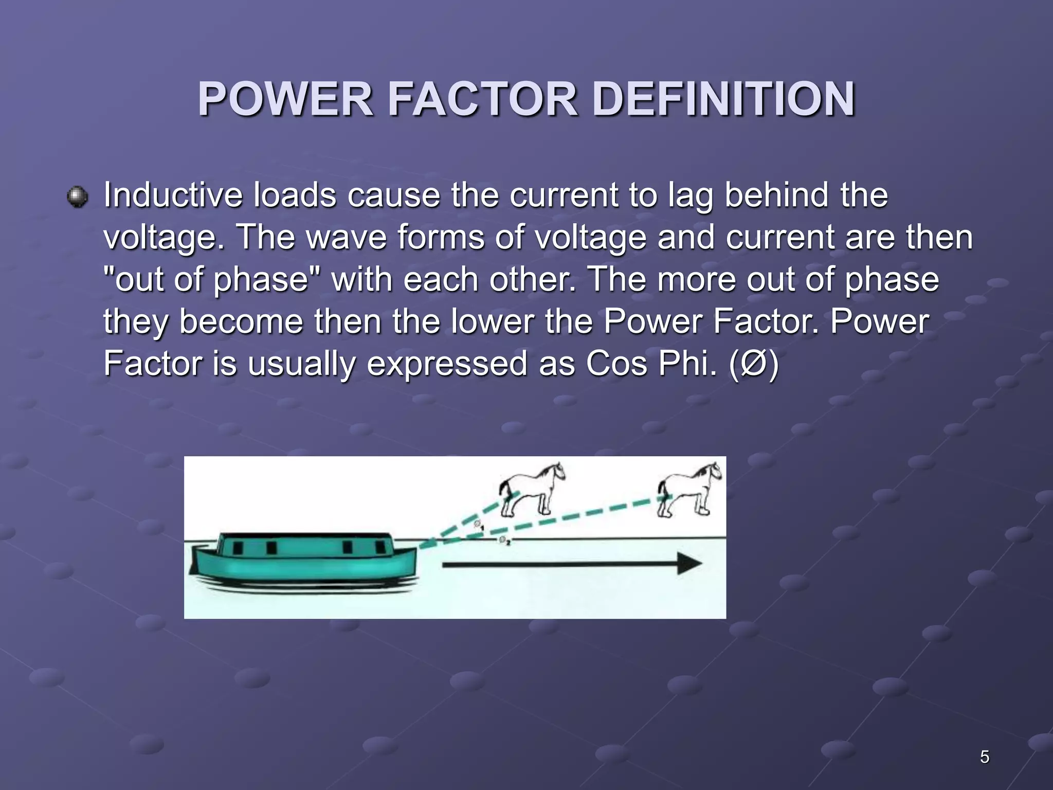
POWER FACTORDEFINITION
Inductive loads cause the current to lag behind the
voltage. The wave forms of voltage and current are then
"out of phase" with each other. The more out of phase
they become then the lower the Power Factor. Power
Factor is usually expressed as Cos Phi. (Ø)
6.
6
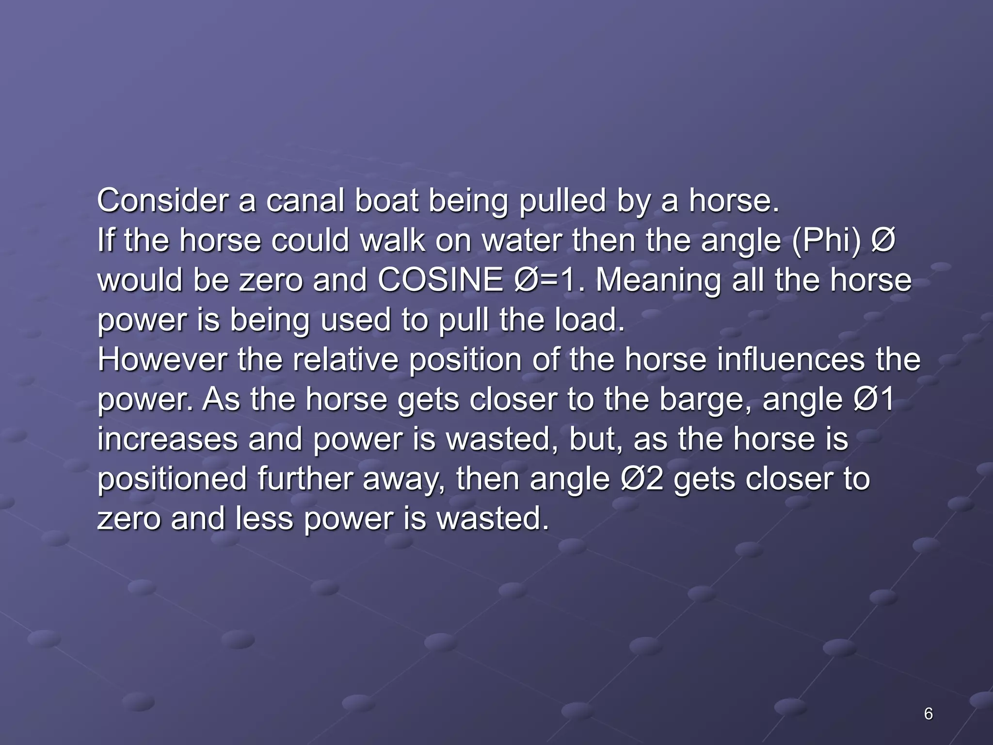
Consider acanal boat being pulled by a horse.
If the horse could walk on water then the angle (Phi) Ø
would be zero and COSINE Ø=1. Meaning all the horse
power is being used to pull the load.
However the relative position of the horse influences the
power. As the horse gets closer to the barge, angle Ø1
increases and power is wasted, but, as the horse is
positioned further away, then angle Ø2 gets closer to
zero and less power is wasted.
7.
7
CAUSES OFLOW POWER FACTOR
A poor power factor can be the result of either a
significant phase difference between the voltage and
current at the load terminals or it can be due to a high
harmonic content or distorted/discontinuous current
waveform. Poor load current phase angle is generally the
result of Poor load current phase angle is generally the
result of an inductive load such as an induction motor
power transformer, lighting ballasts, welder or induction
furnace, Induction generators Wind mill generators and
high intensity discharge lightings.
8.
8
CAUSES OFLOW POWER FACTOR
A distorted current waveform can be the result of a
rectifier variable speed drive, switched mode power
supply, discharge lighting or other electronic load.
9.
9
POWER FACTORCORRECTION
Power factor decreases with the installation of non
resistive loads such as induction motors, Transformers.
Lighting ballasts and electronic equipments. Power
factors can be corrected by using capacitors. These are
rated in electrical units called VAR or KVAR.One VAR is
equivalent to one volt of reactive power. VAR then are
units of measurement for indicating just how much
reactive power the capacitor will supply.
10.
10
As reactivepower is usually measured in thousands the
letter K is used for thousand. the capacitor KVAR rating
then shows how much reactive power the capacitor will
supply. Each unit of the capacitor's KVAR will decrease
the inductive reactive power demand.
11.
11
POWER FACTORCORRECTION
Most loads on an electrical distribution system fall into
one of three categories; resistive, inductive or capacitive.
In most plant, the most common is likely to be inductive.
Typical examples of this include transformers, fluorescent
lighting and AC induction motors. Most inductive loads
use a conductive coil winding to produce an
electromagnetic field, allowing the motor to function.
12.
All inductive loadsrequire two kinds of power to operate:
Active power (KW) - to produce the motive force
Reactive power (KVAR) - to energize the magnetic field
The operating power from the distribution system is
composed of both active (working) and reactive (non-working)
elements. The active power does useful work in
12
driving the motor whereas the reactive power only
provides the magnetic field.
13.
13
POWER FACTORCORRECTION
The amount of Power Capacitor KVAR required to correct
A system to a desired Power Factor level is the difference
between the amount of KVAR in the uncorrected system
and the amount of desired KVAR in the corrected system.
The most efficient location for power factor capacitors is
at the load. Capacitors work from the point of installation
back to the generating source. Individual motor correction
is not always practical, sometimes it is more practical to
connect larger capacitors on the distribution bus or install
an automatic system at the incoming service along with
fixed capacitors at the load.
14.
14
KVAR CORRECTION
Capacitive Power Factor correction (PFC) is applied to
electric circuits as a means of minimising the inductive
component of the current and thereby reducing the
losses in the supply.
The introduction of Power Factor Correction capacitors is
a widely recognised method of reducing an electrical
load, thus minimising wasted energy and hence
improving the efficiency of a plant and reducing the
electricity bill.
15.
It is notusually necessary to reach unity, i.e. Power
Factor 1, since most supply companies are happy with a
PF of 0.95 to 0.98.
By installing suitably sized switched capacitors into the
circuit, the Power Factor is improved and the value
becomes nearer to 1 thus minimising wasted energy and
improving the efficiency of a plant or power factor can be
increased by synchronous motor or Synchronous
generators.
15
16.
16
POWER FACTORCORRECTION
METHODS
Static Var Compensator(SVC)
Fixed Capcitors
Switch Capacitors
Synchronous Condensors
Static Synchronous Compensator(STATCOM)
Modulated power filter capacitor compensator
17.
17
STATIC VARCOMPENSATOR
(SVC)
The Static Var Compensator (SVC) is a shunt device of
the Flexible AC Transmission Systems (FACTS) family
using power electronics to control power flow and
improve transient stability on power grids [1]. The SVC
regulates voltage at its terminals by controlling the
amount of reactive power injected into or absorbed from
the power system. When system voltage is low, the SVC
generates reactive power (SVC capacitive). When
system voltage is high, it absorbs reactive power (SVC
inductive).
18.
The variation ofreactive power is performed by switching
three-phase capacitor banks and inductor banks
connected on the secondary side of a coupling
transformer. Each capacitor bank is switched on and off
by three thyristor switches (Thyristor Switched Capacitor
or TSC). Reactors are either switched on-off (Thyristor
Switched Reactor or TSR) or phase-controlled (Thyristor
Controlled Reactor or TCR).
18
19.
19
A rapidlyoperating Static Var Compensator (SVC) can
continuously provide the reactive power required to
control dynamic voltage swings under various system
conditions and thereby improve the power system
transmission and distribution performance.
Installing an SVC at one or more suitable points in the
network will increase transfer capability through
enhanced voltage stability, while maintaining a smooth
voltage profile under different network conditions. In
addition, an SVC can mitigate active power oscillations
through voltage amplitude modulation
20.
20
FIXED CAPACITOR
where the load does not change or where the capacitor
is switched with the load, such as the load side of a
Ideally suited for power factor correction in applications
motor contactor. It is suitable for locations using
induction motors, like food processing plants, or
where small multiple loads require reactive power
compensation.
Each Fixed Capacitor Bank is designed for high reliability
and long life. These products are designed for
applications that do not contain harmonic generating
21.
21
SWITCHED CAPACITOR
It is suited for centralized power factor correction in
applications where plant loading is constantly changing,
resulting in the need for varying amounts of reactive
power. An advanced microprocessor-based reactive
power controller measures plant power factor via a
single remote current transformer (included), and
switches capacitor modules in and out of service to
maintain a user-selected target power factor. Typically
applied at service entrance or near fluctuating loads.
22.
22
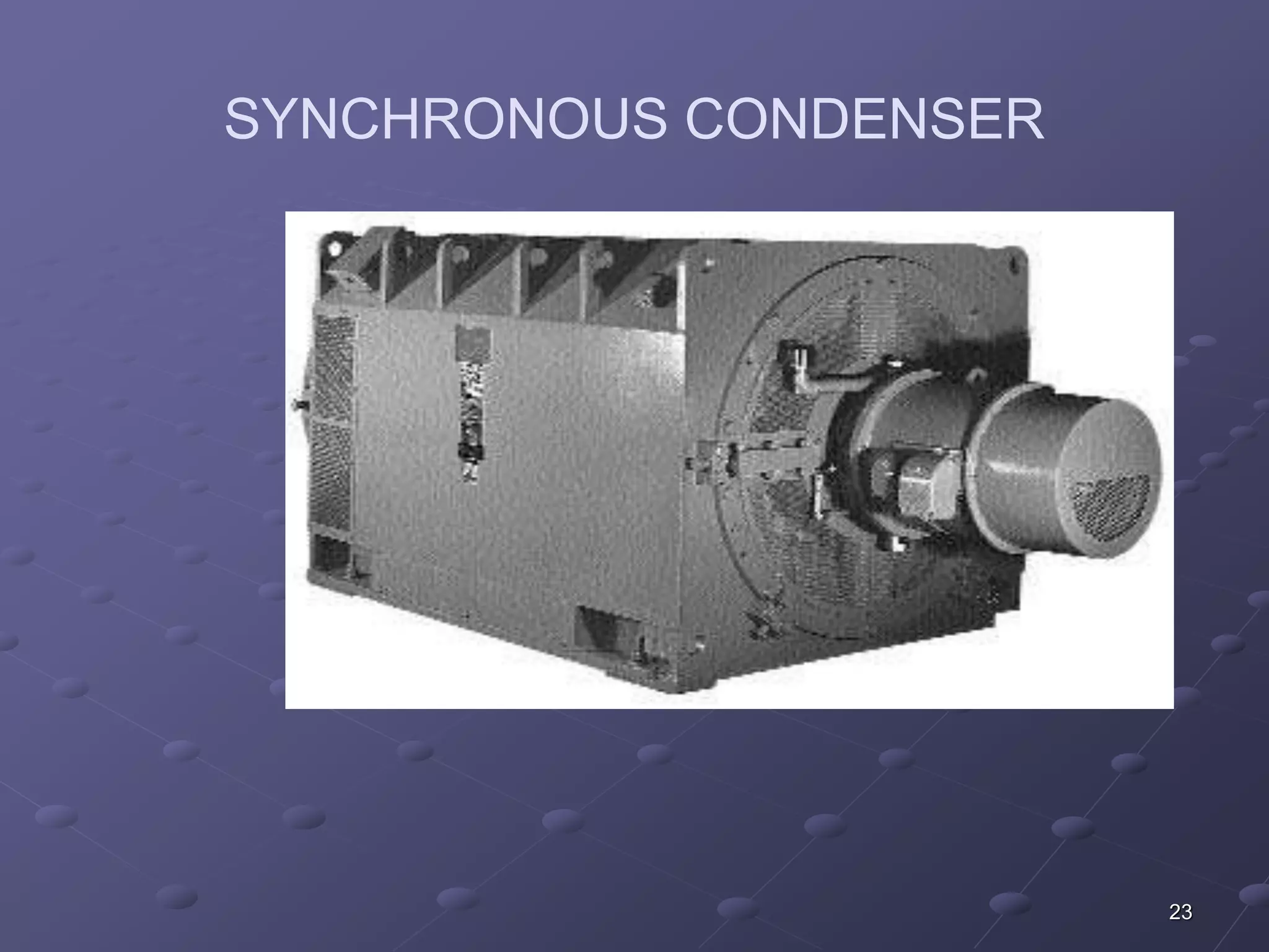
SYNCHRONOUS CONDENSER
Synchronous condenser is a salient pole synchronous
generator without prime mover. Synchronous condenser
stabilizes power system voltage by supplying reactive
power to the power system and Use for power factor
correction. It is more economical than capacitors.
STATIC SYNCHRONOUS COMPENSTOR
24
(STATCOM)
The Static Synchronous Compensator (STATCOM) is a
shunt device of the Flexible AC Transmission Systems
(FACTS) family using power electronics to control power
flow and improve transient stability on power grids [1].
The STATCOM regulates voltage at its terminal by
controlling the amount of reactive power injected into or
absorbed from the power system. When system voltage
is low, the STATCOM generates reactive power
(STATCOM capacitive).
25.
25
When systemvoltage is high, it absorbs reactive power
(STATCOM inductive).Similarly to the SVC the
STATCOM can provide instantaneous and continuously
variable reactive power in response to grid voltage
transients enhancing the grid voltage stability
26.
Installing a STATCOMat one or more suitable points in
the network will increase the grid transfer capability
through enhanced voltage stability, while maintaining a
smooth voltage profile under different network
conditions. The STATCOM provides additional versatility
in terms of power quality improvement capabilities
26
27.
27
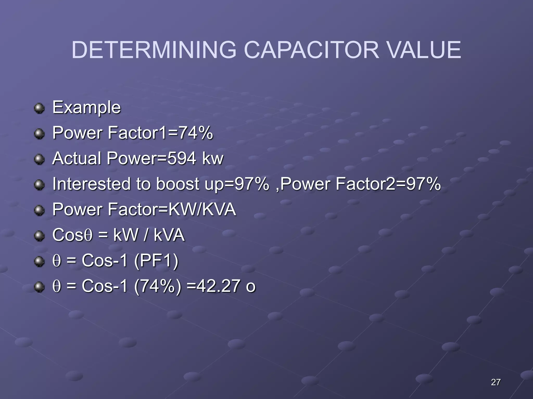
DETERMINING CAPACITORVALUE
Example
Power Factor1=74%
Actual Power=594 kw
Interested to boost up=97% ,Power Factor2=97%
Power Factor=KW/KVA
Cos = kW / kVA
= Cos-1 (PF1)
= Cos-1 (74%) =42.27 o
28.
28
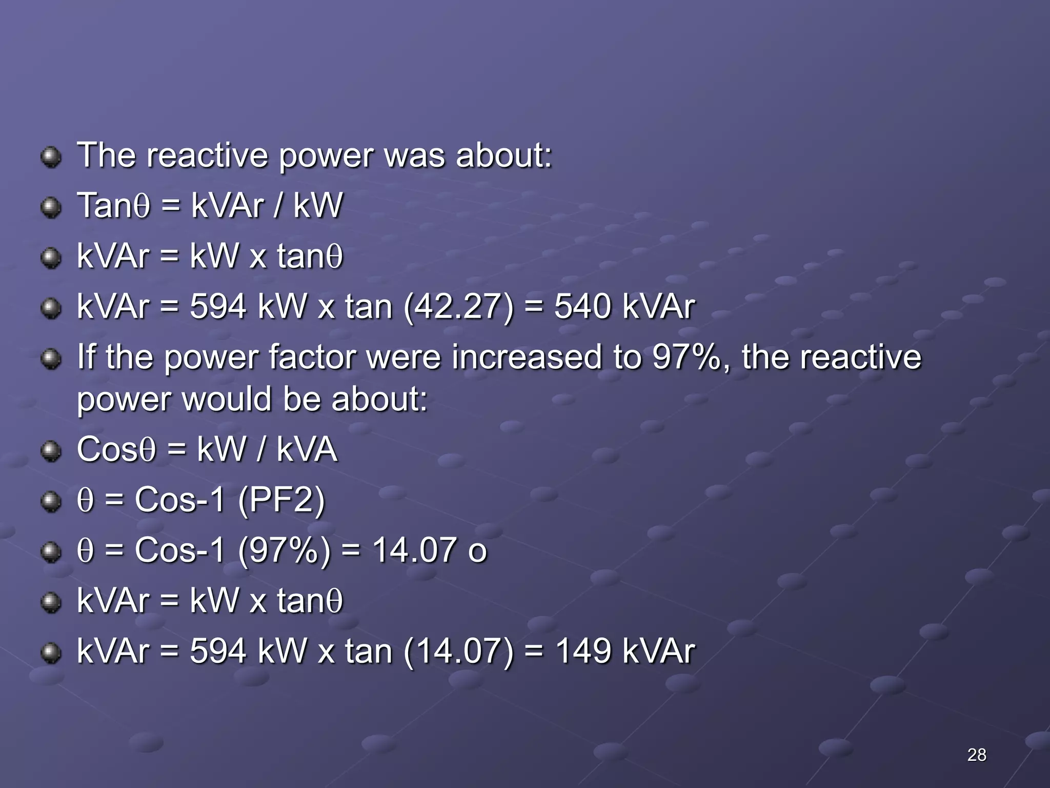
The reactivepower was about:
Tan = kVAr / kW
kVAr = kW x tan
kVAr = 594 kW x tan (42.27) = 540 kVAr
If the power factor were increased to 97%, the reactive
power would be about:
Cos = kW / kVA
= Cos-1 (PF2)
= Cos-1 (97%) = 14.07 o
kVAr = kW x tan
kVAr = 594 kW x tan (14.07) = 149 kVAr
29.
29
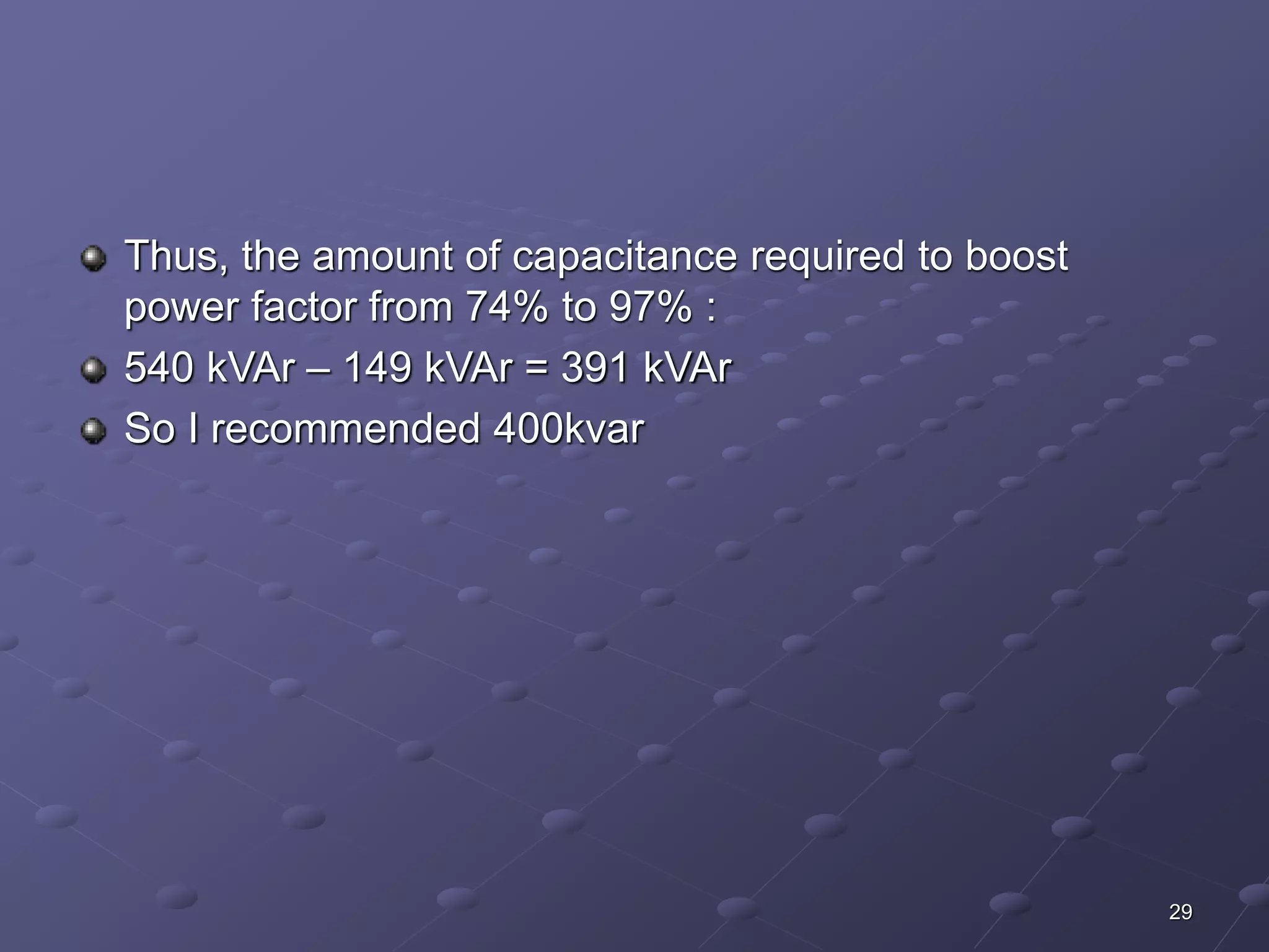
Thus, theamount of capacitance required to boost
power factor from 74% to 97% :
540 kVAr – 149 kVAr = 391 kVAr
So I recommended 400kvar
31
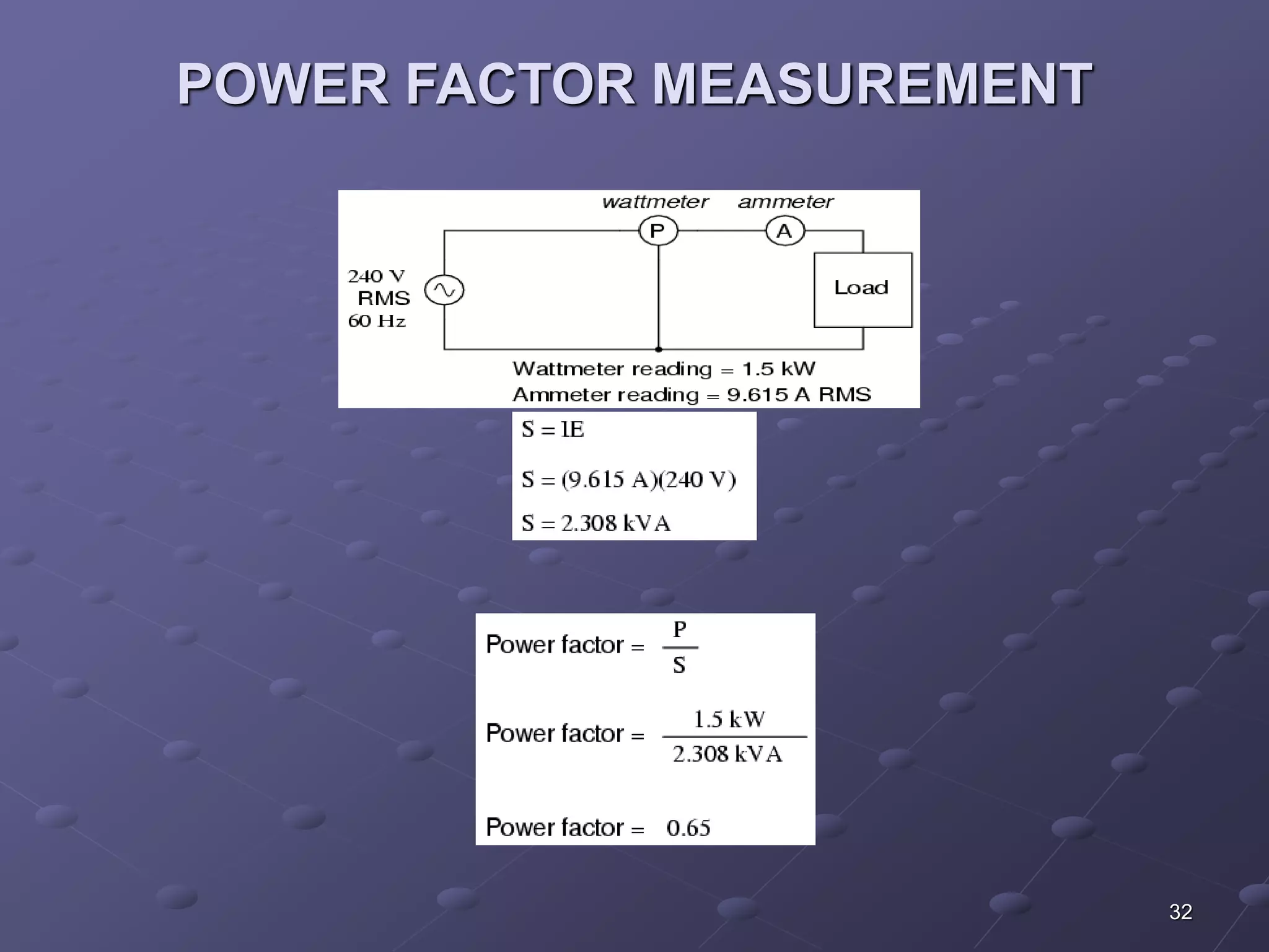
POWER FACTORMEASUREMENT
Power factor can measure by using power factor meter
which is well known in power industry.
Power factor can also be calculated by installing watt
meter along with the Ampere meter and volt meter by
using the power factor basic formula.
Power factor=Actual Power/ Apparent power
33
ADVANTAGES OFPOWER FACTOR
CORRECTION
Eliminate Power Factor Penalties
Increase System Capacity
Reduce Line Losses in distribution systems
Conserve Energy
Improve voltage stability
34.
34
Increase equipmentlife
Save on utility cost
Enhance equipment operation by improving voltage
Improve energy efficiency
35.
Reduction in sizeof transformers, cables and switchgear
in new installations.
Delay costly upgrades.
Less total plant KVA for the same KW working power.
Improved voltage regulation due to reduced line voltage
drop.
35
36.
36
POWER COSTREDUCTION
Utility companies in many areas include a penalty charge in
the electrical rate for low power factor. The installation of
power factor capacitors on the user's electrical distribution
system eliminates the necessity of paying premium rates to
the utility company for poor power factor.
37.
37
The savingsthe utility company derives in reduced
generation, transmission and distribution costs are
passed on to the user in the form of lower electrical
charges. Three of the more common ways a utility
charges a user for poor power factor are based on
38.
38
KW demandwith a trigger point typically between 85%
and 95%
KVA demand
KVAR demand
When the utility uses either KVA demand or KVAR
demand as the basis for its penalty structure, all users
pay a penalty, but those with high power factor pay a
much lower penalty or none at all.
39.
39
SYSTEM CAPACITYINCREASE
By adding capacitors to the system, the power factor is
improved and the KW capacity of the system is
increased. For example, a 1,000 KVA transformer with a
70% power factor provides 700 KW of power to the main
bus. With the installation of capacitors so that the power
factor is improved, say, to 90%, the KW capacity of the
system is increased to 900 KW. When a system power
factor is improved, the amount of reactive current flowing
Is lowered thus reducing transformer and distribution
circuit loads, and releasing system capacity.
40.
40
VOLTAGE IMPROVEMENTAND POWER
LOSS REDUCTION
System losses are also reduced through power factor
correction by reducing the total current and power in the
system. A 20% reduction in current will yield a 36%
reduction in distribution system losses. In this situation,
an energy savings of as much as 50% will be realized
with the installation of power factor capacitors.
In addition, power factor capacitors decrease the
distribution system voltage drops and fluctuations.
41.
41
DISADVANTAGES OFLOW POWER
FACTOR
Increases heating losses in the transformers and
distribution equipments.
Reduce plant life.
Unstabilise voltage levels.
Increase power losses.
Upgrade costly equipments.
Decrease energy efficiency.
Increase electricity costs by paying power factor
surcharges.
42.
42
CONCLUSION
Byobserving all aspects of the power factor it is clear that
power factor is the most significant part for the utility
Company as well as for the consumer. Utility company
rid of from the power losses while the consumer free
from low power factor penalty charges.
By installing suitably sized power capacitors into the
circuit the Power Factor is improved and the value
becomes nearer to 1 thus minimising line losses and
improving the efficiency of a plant.
43.
43
REFERENCES
ElectricalPower System Design and Analysis
by M.E.EI-Hawary.
Power System Operations
by Robert H Miller.
IEEE papers
www.ABB.com
BC Hydro (www.bchydro.ca)

![17
STATIC VAR COMPENSATOR
(SVC)
The Static Var Compensator (SVC) is a shunt device of
the Flexible AC Transmission Systems (FACTS) family
using power electronics to control power flow and
improve transient stability on power grids [1]. The SVC
regulates voltage at its terminals by controlling the
amount of reactive power injected into or absorbed from
the power system. When system voltage is low, the SVC
generates reactive power (SVC capacitive). When
system voltage is high, it absorbs reactive power (SVC
inductive).](https://image.slidesharecdn.com/ppt051-140902100306-phpapp01/75/Power-Factor-17-2048.jpg)
![STATIC SYNCHRONOUS COMPENSTOR
24
(STATCOM)
The Static Synchronous Compensator (STATCOM) is a
shunt device of the Flexible AC Transmission Systems
(FACTS) family using power electronics to control power
flow and improve transient stability on power grids [1].
The STATCOM regulates voltage at its terminal by
controlling the amount of reactive power injected into or
absorbed from the power system. When system voltage
is low, the STATCOM generates reactive power
(STATCOM capacitive).](https://image.slidesharecdn.com/ppt051-140902100306-phpapp01/75/Power-Factor-24-2048.jpg)